HAL Id: hal-01801012
https://hal.archives-ouvertes.fr/hal-01801012
Submitted on 28 May 2018HAL is a multi-disciplinary open access
archive for the deposit and dissemination of sci-entific research documents, whether they are pub-lished or not. The documents may come from teaching and research institutions in France or abroad, or from public or private research centers.
L’archive ouverte pluridisciplinaire HAL, est destinée au dépôt et à la diffusion de documents scientifiques de niveau recherche, publiés ou non, émanant des établissements d’enseignement et de recherche français ou étrangers, des laboratoires publics ou privés.
Shiqi Wang, Lucien Baldas, Stéphane Colin, Stéphane Orieux, Nicolas
Laurien, Azeddine Kourta, Nicolas Mazellier, Stéphane Loyer
To cite this version:
Shiqi Wang, Lucien Baldas, Stéphane Colin, Stéphane Orieux, Nicolas Laurien, et al.. Active flow control of ramp flow by fluidic oscillators. 2nd MIGRATE International Workshop, Jun 2017, Sofia, Bulgaria. �hal-01801012�
1
migrate2017:154498
ACTIVE FLOW CONTROL OF RAMP FLOW BY FLUIDIC
OSCILLATORS
Shiqi Wang
1, Lucien Baldas
1, Stéphane Colin
1,
Stéphane Orieux
1, Nicolas Laurien
1,
Azeddine Kourta
2,
Nicolas Mazellier
2, Stéphane Loyer
2 1Institut Clément Ader (ICA), Université de Toulouse, CNRS, INSA, ISAE-SUPAERO, Mines Albi, UPS, Toulouse France [email protected], [email protected], [email protected], [email protected], [email protected]
2Université d’Orléans; INSA-CVL; PRISME EA 4229, Orléans, F45072, France
[email protected], [email protected], [email protected]
KEY WORDS
Separation control, hot wire, PIV, momentum coefficient
ABSTRACT
The study of actuators for active flow control has been in rapid expansion in the last several decades, pursuing different goals such as reducing drag on bluff bodies1, increasing lift of airfoils2, 3 or enhancing mixing in combustion chambers4, 5. Compared to traditional passive control methods or steady blowing method, the active flow control based on periodic fluidic excitations is much more efficient, with a gain of two orders of magnitude in terms of added momentum coefficient, as demonstrated by numerous researches (e.g. Greenblatt and Wygnanski 6). These periodic fluidic disturbances can be provided by various kinds of actuators such as ZNMF (Zero Net Mass Flow) actuators, plasma actuators or MEMS (Micro-Electro-Mechanical-Systems)7. Among them, fluidic oscillators can emit oscillating jets in a large operating frequency and velocity range when supplied with a pressurized fluid without requiring any moving part, since their oscillations are totally self-induced and self-sustained and only depend on the internal flow dynamics, which is a great advantage in terms of reliability and robustness8-10.
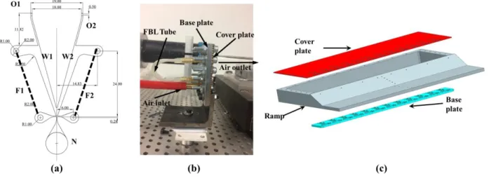
A typical fluidic oscillator is basically composed of an inlet nozzle N, two feedback loops F1 and F2 and two outlets O1 and O2, as shown in Figure 1a. Its behavior is based on the Coanda effect: the jet issuing from nozzle N attaches one of the two walls W1 or W2. The attachment either to wall W1 or wall W2 depends on the initial conditions or is the result of specific actions on the jet. If there was no feedback loop and if the outlet sections were large, the attachment to wall W1 or wall W2 would be stable and the flow would exit through the corresponding outlet, O1 or O2, respectively. With feedback loops, when the jet is attached to wall W1, part of the flow fills in the feedback loop F1 and a pressure increase in the left side of the device is observed, due to the hydraulic restriction at outlet O1. This pressure increase forces the jet to switch toward the right side. Following the jet switching, the same phenomenon develops in the right side of the oscillator and results in a self-sustained oscillating behavior, with a pulsed flow alternatively exiting outlets O1 and O2. In the current design, the feedback loops are plastic tubes as shown in Figure 1b, connected perpendicularly to the base plate. The channels of the oscillator’s central part are milled in the base plate in a depth of 370 µm while the outlet slot is milled in the cover plate with an area of 0.5 mm2 . The throat section of inlet nozzle has a width of about 200 µm. The outlet jet has the same direction as the inlet air.
After examining by hot wire the frequency and velocity response of an isolated oscillator to inlet pressure, an array of 12 identical fluidic oscillators is integrated in a ramp with a 25° slant angle by assembling the cover plate, the base plate and the ramp together as shown in Figure 1c. The centers of outlet
2
holes of the array are at a distance of 200 µm upstream from the ramp slant edge. The efficiency of this fluidic oscillator array on the ramp separation flow is measured in the S2 wind tunnel, in PRISME laboratory, Orléans. The 2D mean velocity fields are captured by using a 2D PIV system. PIV images are focused on the centerline plane of the ramp.
Figure 1: a) sketch of a typical fluidic oscillator; b) photo of a real fluidic oscillator during test; c) sketch of the
designed ramp
The 2D mean velocity fields are measured in 4 cases, which are the baseline flow without control and the flow controlled with the fluidic oscillators supplied at 3 different pressure levels. In all cases, the main flow velocity is 20 m/s, corresponding to a Reynolds number Re =3.8×10⁴ based on the ramp height (h=30 mm) as a characteristic length. In the controlled cases, inlet pressures are Pi = 0.2, 0.25 and 0.3 MPa
respectively, and their corresponding control parameters are presented in Table 1.
f is the measured frequency of the synchronized fluidic oscillator array, while U and b rms b
U are the mean and the root mean square values of the blowing velocity in each outlet slot. Assuming that the jet sinusoidally oscillates, the momentum coefficient defined as a ratio of the momentum added to that in the free-stream can be calculated as 6:
2 2 2 2 ( ) 1 1 2 2 rms b b b b m U N U U A C U L U L (1)
where m and b U are the instantaneous blowing mass flow rate and velocity of the outlet jets, N is the b
total number of outlet slots which is N = 24, A is the outlet slot area, ω is the width of the ramp, L is a characteristic length, here chosen as the length between the ramp slant edge and the separation reattachment point in the baseline flow without control and is the free stream flow velocity.
Pi (MPa) 0.2 0.25 0.3 f (Hz) 716 660 660 b U (m/s) 44 57 70 rms b U (m/s) 6.4 7.7 9.2 C 0.16% 0.27% 0.41%
Table 1: control parameters of three controlled flow cases
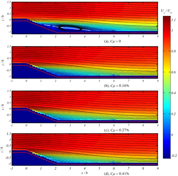
The mean velocity fields in the streamwise direction obtained in both baseline case and controlled cases are shown in Figure 2. In the baseline case (C 0), the red line Ux 0 highlights the upper limit of the
3
region where the flow is reversed. This recirculation region terminates at approximately x h/ 4.8. In the first controlled case (C 0.16%), the flow separation has been totally eliminated and no reversed flow can be observed. When Ccontinues increasing to 0.27%, the situation becomes even better as the minimum
x
U velocity becomes higher. In case of C 0.41%, no significant modification can be observed compared to the case C 0.27%. The obtained results show that this fluidic oscillator array is very promising for active separation flow control considering the low momentum coefficient needed to totally eliminate the separation.
Figure 2: average Ux field contours under various conditions Acknowledgements
The authors acknowledge the scholarship offered by China Scholarship Council (CSC).
References and Citations
[1] Aubrun, S., McNally, J., Alvi, F., and Kourta, A. (2011), Separation flow control on a generic ground vehicle using steady microjet arrays, Experiments in Fluids Vol. 51, No. 5, pp. 1177-1187.
[2] Melton, L., Hannon, J., Yao, C.-S., and Harris, J. (2008), Active flow control at low Reynolds numbers on a NACA 0015 airfoil, 26th Applied Aerodynamics Conference. Number AIAA. Vol. 6407, p. 2008. 0 z / h (a), C = 0 -1 0 1 2 3 4 5 6 7 8 9 -1 -0.5 0 0.5 1 1.5 z / h (b), C = 0.16% -1 0 1 2 3 4 5 6 7 8 9 -1 -0.5 0 0.5 1 1.5 z / h (c), C = 0.27% -1 0 1 2 3 4 5 6 7 8 9 -1 -0.5 0 0.5 1 1.5 x / h z / h (d), C = 0.41% -1 0 1 2 3 4 5 6 7 8 9 -1 -0.5 0 0.5 1 1.5 U x / U -0.2 0 0.2 0.4 0.6 0.8 1 1.1
4
[3] Lin, C.-Y., and Hsiao, F.-B. (2013), Experimental Study of Flow Separation over NACA63 3 018 Wing with Synthetic Jet Control at Low Reynolds Numbers, Journal of Mechanics Vol. 29, No. 01, pp. 45-52.
[4] Fanping, S., Ray-Sing, L., Martin, H., and Tory, B. (2002), Air Flow Control by Fluidic Diverter for Low NOx Jet Engine Combustion, 1st Flow Control Conference. American Institute of Aeronautics and Astronautics.
[5] Daniel, G., Bernhard, B., Christian Oliver, P., and Surya, R. (2008), Active Combustion Control Using a Fluidic Oscillator for Asymmetric Fuel Flow Modulation, 44th AIAA/ASME/SAE/ASEE Joint
Propulsion Conference & Exhibit. American Institute of Aeronautics and Astronautics.
[6] Greenblatt, D., and Wygnanski, I. J. (2000), The control of flow separation by periodic excitation,
Progress in Aerospace Sciences Vol. 36, No. 7, pp. 487-545.
[7] Cattafesta III, L. N., and Sheplak, M. (2011), Actuators for active flow control, Annual Review of
Fluid Mechanics Vol. 43, pp. 247-272.
[8] Ciro, C., and Emad, G. (2007), An Experimental and Numerical Investigation on Fluidic Oscillators For Flow Control, 37th AIAA Fluid Dynamics Conference and Exhibit. American Institute of Aeronautics and Astronautics.
[9] Gregory, J. W., Sullivan, J. P., Raman, G., and Raghu, S. (2007), Characterization of the Microfluidic Oscillator, AIAA Journal Vol. 45, No. 3, pp. 568-576.
[10] Bobusch, B. C., Woszidlo, R., Bergada, J. M., Nayeri, C. N., and Paschereit, C. O. (2013), Experimental study of the internal flow structures inside a fluidic oscillator, Experiments in Fluids Vol. 54, No. 6, pp. 1-12.