TIMBER CONSTRUCTION METHODS FOR ROOF STACKING:
CLASSIFICATION AND COMPARATIVE ANALYSIS
Mohamed Amer
1, Shady Attia
2ABSTRACT: As a mean of accommodating increasing population in major cities around Europe, new agendas for
urban densification emerge in response of finding sustainable solutions. Several methods for urban densification are proposed and seen in real life. Roof stacking has been proposed as a way to promote for sustainable urban densification. This paper presents the results of a conducted investigation on roof stacking assembly and construction methods using timber construction. A classification for different roof stacking has been proposed, followed by a comparative analysis between different methods. The comparative analysis identifies the advantages, disadvantages, and best practice of each method. A parametric simulation and multi-objective optimization have been carried out for two different methods to identify the optimum timber construction for roof stacking. The results shed the light on the solutions and recommended timber construction method according to the comparative analysis.
KEYWORDS: Lightweight, Decision making, Urban densification, Compact city, Vertical extension, Rooftops
1 INTRODUCTION
123
1.1 POPULATION AND URBANISATION
According to the latest studies by the United Nations, world population is expected to reach 9.425 billion by the year 2050, with 32 % increase in population equivalent to more than 2.37 billion [1]. This increase is followed by several migration movements, polarization of intellectuals, which contribute to an inevitable increase in housing demand [2]. Accordingly, urban growth has been witnessed in several cities that face this increase. However, studies reported that this growth is higher in frequency than the growth rates in urban population [3]. Given that 54 % of the world’s population live in urban areas, this ratio will to increase up to 66% in 2050 [4]. Thus, new neighborhoods are needed to be built which pushes the borders of the cities creating larger outskirts with lower densities. This contributes to the loss of farmlands, increasing carbon emissions and affects negatively the local climate of the region [5]–[7]. The phenomena of losing farmland is confirmed by another study that reported that European cities became less compact with an average expansion of 78% for urbanized area while 33% only for the population in the last 60 years [8]. As a result, the consumption of agriculture lands by the act of urban sprawling is predicted to continue in all parts of Europe. More than 5% of the current agriculture land will be converted into sealed surfaces in Scandinavia, UK, Central Europe and Mediterranean coastal areas. Whereas the Netherlands, Belgium and France will
1 Mohamed Amer, Sustainable Buildings Design Lab, Université de Liège, [email protected] 2 Shady Attia, Sustainable Buildings Design Lab, Université de Liège, [email protected]
highly suffer from the loss of agricultural lands, while Germany, Poland and Hungary will face those loses in scattered patterns of their lands [9]. Several governments made some attempts to limit urban sprawling by creating boundary zone between urban and rural areas aiming to manage an efficient usage for urban areas, such as the Green Belt Policy in the UK, the Green Heart in the Netherlands and Innerstadt projects in Germany [10]; however, negative consequences were followed by these policies by stepping out the boundary zone leading to undesirable impacts on the countryside [11].
1.2 TOWARDS DENSIFICATION
In the recent years, new research agendas for urban densification started to emerge in response to the upcoming needs of Europe to accommodate increasing population while limiting urban sprawling [12]. Many researchers have explored the implications of urban densification stating that higher densities support efficient infrastructure and reduces carbon emissions [13]–[17]. Others argue that more compact forms significantly reduce the energy consumption on the building and transportation scale [18]–[20]. Marique and Reiter [21] found that by increasing the density of a neighborhood alone without applying retrofitting measures can reduce up to 30% of the total energy consumption. Nilsson [10] came up with four strategies as an approach towards sustainable urban-rural futures, one of them was to contain and densify cities and suburbs while developing a green compact city. Yet, a package of polices should be provided to integrate increasing urban density with higher concentrations of employments, good transit network, parking areas and carbon taxing system [22]–[25].
There are several urban densifications have been witnessed, such as building in the backyards [21], or by closing gaps and vacant lots between buildings. An example can be given for the initiative made by the city of Cologne in Germany that is called “Baulückenprogramm” or “Building gaps program”. As a results, there have been more than 20,000 new apartments realized by filling the gaps between existing buildings [26], [27]. Another aggressive method is realized by demolishing existing buildings and reconstructing new buildings with higher densities and more dwellings. While the last method, which is concerned in this research, is by adding additional stories on the rooftops of the existing buildings which can be described as roof stacking [28], [29].
1.3 ATTEMPTS FOR CLASSIFICATION
Roof stacking as an approach towards increasing urban density has many advantages. Roof stacking approach has the benefit of conserving the vacant areas, promoting for a balance between urban densification and the preservation of green areas as recommended by several researches [10]. Moreover, in terms of energy efficiency, it was found that applying roof stacking is more efficient that roof renovation when it comes to the reduction of the total energy consumption. According to Tichelmann and Groß, it was found that roof stacking can reduce the total energy consumption by 17% compared to flat roof renovation, and 6% compared to saddle roof renovation [30].
There have been attempts to classify roof stacking. One research attempted to classify roof stacking based on the shape of the roof stacking modules [31]. The cases were classified into five types; roof shaped (usually saddle shaped roof), Cubic form aligning the roof surface, set back extension, free form or cantilevered, combined extension with the main building volume, and lastly juxtaposed extension to the main building. Another attempt was made to classify roof stacking based on their constructive characteristics, the number of added stories and the percentage of their roof space occupation [30]. Four main categories were identified; one added saddle shaped roof, one added flat roof floor, two added floors, and lastly three and more added floors. In this article, the classification counted on the case studies that were investigated by previous literature. In addition, more cases gathered from different resources were further studied, such as the investigation made by (ROBUST), a European research project aimed to study building technology and building physics issues associated with the renovation, roof stacking and improvement of existing buildings using steel-based technologies [32], while other cases were specifically designed by well-known architectural offices, by which a systematic approach and concept were developed throughout the whole process [33], [34].
This paper aims to promote for a systematic approach for roof stacking using lightweight construction as a mean of sustainable urban densification and development. In addition, given the potential of timber in achieving high levels of carbon neutrality and sustainable city, there are wide range of wall configurations that could be
deployed. However, choosing the right building configuration under conflicting objectives, such as achieving energy efficient building and reducing the total weight of construction, has always been a struggle for architects and designers in the early design phases. The research questions of this paper are; what are the applied construction methods of roof stacking? And what are the optimum design configurations that could be achieved using timber construction? Accordingly, there are two main objectives; first, is to classify the construction methods and building materials that are currently used for roof stacking. Second, is to aid the decision making on the selection process of building envelope to achieve energy efficient, lightweight roof stacking modules.
2 METHODOLOGY
This paper is a part of an ongoing research that aims to increase the urban density by validating design prototypes for different zero energy, lightweight construction systems and composite components. This article focuses particularly on reviewing roof stacking projects around Europe that adopted timber construction, aiming to provide a guideline to aid the decision support on the optimum configurations of building envelope for roof stacking construction. Thus, a methodology has been designed to identify optimum measures for energy efficient lightweight roof stacking modules. The methodology in this article consists of two main parts. In the first part of this research, a systematic classification and analyses have been conducted to illustrate different construction methods. Over 60 case studies around Europe have been gathered and reviewed throughout different literatures based on predefined criteria as following. The first selection criterion is according to the geographical context. Since this research targets in its first phase the European construction sector, the cases were gathered from 13 European countries. The second criterion is according to functional and scale context. However many cases that were found were occupied by different functions, in this research only cases with a residential function have been reviewed. The third and last criterion is according to the available information on each case. Many of the cases that have been spotted had no sufficient information to build an analysis on, therefore many spotted cases were excluded from the reviewing process. Afterwards, a comparative analysis has been carried out between different methods of roof stacking in terms of benefits, drawbacks, and best practices.
In the second part, methods that employed timber construction have been selected for deep investigation. The reason behind the selection of timber construction for investigation is due to the fact that it aligns with the Euro vision in providing expand cost-effective housing opportunities and provide leadership to accelerate the transformation towards a low carbon community. Thus, there is a need to provide guidance for best practice solutions for timber construction to achieve optimum building performance. A parametric analysis has been conducted for different wall sections using timber based
materials, for structure and insulation, generating more than 3,000 design wall configurations. Parametric simulation has been followed by a multi-objective optimization for two design objectives; energy consumption and weight of construction, in order to choose optimum design configuration.
3 ROOF STACKING CLASSIFICATION
& COMPARATIVE ANALYSIS
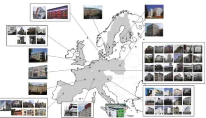
Over 60 roof stacking cases around Europe have been listed, documented and further analysed as shown in Figure 1. Those cases were gathered from different resources with different classification approaches and descriptions. In this research, the classification in this research is based on the building materials used as main structure, and assembly method. According to the review, four different common building materials are sued for roof stacking; steel, timber, lightweight concrete, and composite materials (steel and timber). While there are three main methods for assembly; offsite construction by manufacturing 3D units, onsite assembling of 2D elements such as walls and roofs, and onsite assembling of 1D elements such as beams and columns.
Figure 1: Case Studies around Europe classified and analysed
3.1 BUILDING MATERIALS
Existing buildings with roof stacking cases were characterized by two different structural systems. Buildings that return back to the nineteenth century and early twentieth century had load bearing constructional system counting on the exterior massive walls, while buildings from late twentieth century had skeleton structure out of reinforced concrete or steel structure [31]. Building materials that have been involved in the process of roof stacking for a structural purpose have been documented throughout the 60 different analyzed cases. Even though multiple materials have been listed, it was possible to classify them under 4 main types; reinforced concrete, steel, timber, and composite (a mixture of steel and timber), while the structure of the existing buildings were found in 3 main building materials; Masonry, reinforced concrete and steel as shown in Figure 4.
Figure 2: Classification of existing buildings’ materials
Figure 3: Classification and usage frequency of building materials used for roof stacking
As shown in Figure 5, it was found that more than 50% of the building materials used on buildings with massive structures was made out of lightweight steel, which has a tendency to reflect a modern style contrary to the original style of the existing building. Using timber comes in the second place, while the usage of reinforced concrete comes at the last place. On the other side, timber had more than 50% of usage for RC buildings, while light weight steel structures comes in the second stage with around 30% and RC only 14%. Existing buildings with steel skeleton always accommodated extensions made of steel structures or a mixture of steel and timber, however no RC was found to be used over steel structure. The choice of building materials has a direct influence on the total weight per square meter on the original building. Thus, a wise choice of the materials’ mixture is important to meet the required aesthetic, structural and energy performance.
3.2 ASSEMBLY METHODS
Installation method highly depends on urban context and site condition, available tools and technology, and occupants’ adaptability. Two main categories are found under the installation methods, the first is off-site assembly, which produces ready 3D units, while the second is onsite assembly of 1D and 2D elements. However, both methods share the same dependency on prefabrication technology, since it is nearly impossible to carry out a full construction on the rooftop.
3.2.1 Offsite assembly
As shown in Figure 4, building elements are assembled offsite to form complete or partial 3D modules. Those modules are transferred to the site, lifted and installed on the rooftop of the existing building. Assembling prefabricated units takes the least time onsite, up to three days [33], for installation and assembly, which is considered as an advantage especially for the cases with high traffic or less working spaces. Those units can be in the form of containers, partial or full residential units. They are totally manufactured in the factory, including structural system, walls, floor and ceiling. As a prerequisite, onsite preparations such as clearing the roof and mounting joints should take place before the installation of the units. This method counts on the modularity of the design and modest requirements by prospect inhabitants. However, finishing process including interior and exterior plastering, electricity outlets and sanitation always takes place onsite. Such a method of manufacturing and installation requires a full coordination and integration between the designer and the manufacturer, in addition to the option of having such manufacturing company that provides such a service. Precise measurements for the roof and onsite conditions are prerequisites for a successful assembling procedure and to minimize expected errors for transportation and lifting the elements onto the rooftop.
Figure 4: Offsite 3D modules manufacturing, Barcelona, Spain © La Casa Por El Tejado
3.2.2 Onsite assembly
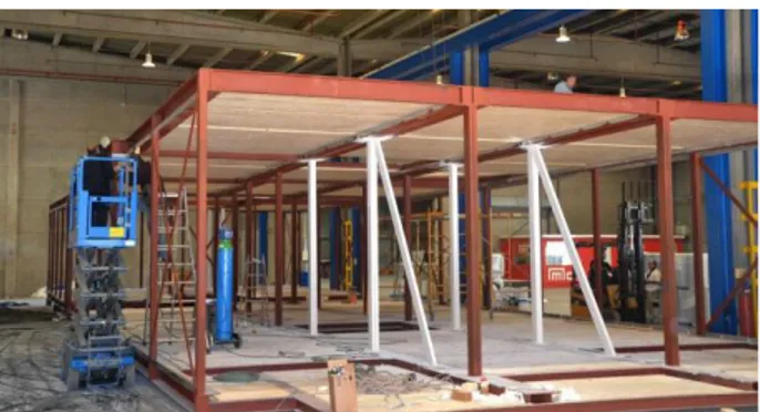
When a project entails higher complexity in the design, onsite assembly resembles a better option. However, less restriction in terms of for occupying the building and its surroundings for longer durations are required. Assembling prefabricated elements suits architectural designs with less modularity and bigger sizes. It is also easier in terms of transportation and lifting. However, this method requires further consideration for the joins design and the assembly techniques between the different architectural elements [32]. Prefabrication can be processed into two forms; the first is prefabricating construction 2D elements as shown in Figure 5, such as walls, ceilings, and floors, or prefabricating 1D elements, as shown in Figure 6, such as beams, columns or whole frames. While, the benefits of the onsite total construction and assembling prefabricated elements are achieved, it still consumes more time than other methods. Some cases were recorded, by which it did not require a total evacuation for the building form its inhabitants [32].
The first method of assembling 2D elements on the rooftop consumed more time relatively when compared to installing 3D modules. It counts on precisely fabricated walls and slabs in the factory with numbering, which are transported and lifted by smaller cranes and assembled on the rooftop directly. 2D elements may include doors and windows and may not, however they are usually having only the ready cuts while the other elements come at a later stage. The most important thing that has to be taken in consideration in this method is the design of the joints between the different elements. They have to be included and fabricated in the 2D elements before arrival onsite.
In contrary, prefabricated 1D elements are represented in beams, columns, frames, etc. Onsite construction consumes time compared to other methods. Such conditions should secure enough time, acceptance from the neighbours and having the space to assemble and connect the elements together onsite. Sometimes the existing roof has to function during the construction process, which can represent a huge challenge.
Figure 5: Plywood wall elements assembly, Kierling, Austria © Architekturbüro Reinberg
Figure 6: Sleep well in the sky Project, Brussels, Belgium © Atelier d’Architecture Galand
Table 1: Comparison between different installation techniques
Off-Site Assembly On-Site Assembly
3D Units 2D Elements 1D Elements
B
est Pr
ac
tice
In dense neighborhoods and busy traffic
Buildings busy with Occupants Neighborhood with relatively wide
streets
Stacking with special requirements and complex designs
[35]
Doable for dense neighborhoods and busy traffic
Less urbanized or inhabited areas Unoccupied buildings or tolerant
neighbors and / or occupants [36]
Pre
req
u
is
ites
Ready system on the roof to rest the modules on
Precision in manufacturing High standard transportation and
lifting cranes [37] Off-site manufacturer
Precision in manufacturing Predesigned assembly method
and joints
Rooftop preparations
Additional space (on the rooftop or a courtyard on the side) for onsite assembly and rooftop lifting
B
en
ef
its The fasted method for roof stacking [37]
Higher Quality for off-site construction
Relatively fast method for construction
Reduces the amount of onsite construction wastes
Easy to transport and lift on the rooftop if needed.
Higher flexibility in assembly and placement on the roof More design variety
Dr
awb
ac
k
s Transportation and lifting of modules
Preciseness of manufacturing The existence of a factory to
produce accustomed modular units Less onsite modifications flexibility
Highly sensitive to errors resulted from miscalculation or
prefabrication
Limited with number of design options based on the modularity of prefabricated elements
Takes more time to assemble on site and install on the roof [36]
4 MULTI-OBJECTIVE OPTIMIZATION
According to the developed classification, it has been observed that on-site assembly methods are widely used compared to the off-site assembly. This wide usage is due to the less expertise needed for design, manufacturing, and assembling. In addition, multiple design variety and configurations could be easily achieved. In this research, a comparative analysis is conducted between two wall sections for two different assembly methods. The first wall section is composed of Cross Laminated Timber (CLT), as the main bearing system, which represents the 2D assembly method. While the second wall section is composed of Timber Framing as the main bearing system, which represents the 1D assembly method.4.1 DESIGN VARIABLES
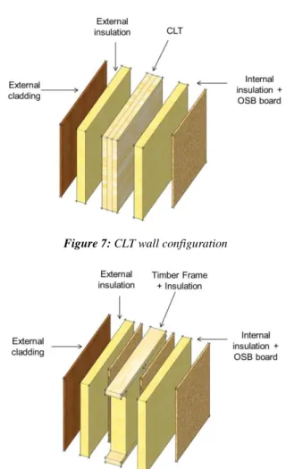
The aim of this step is to examine different wall configurations and compositions in order to achieve energy efficient lightweight roof stacking modules. Several options are given for every assembly method. However, the variables in both methods follow the same approach. As shown in Figures 7 & 8, there is the main structure which is composed of either CLT or Timber Frame, and then there is the variable option of adding external insulation with a range between 50 and 300mm. The same variable option is given with the internal insulation, which ranges between 50 and 100mm. The last variables option is given with the external cladding, which is accompanied by constant air gap of 30mm.
Figure 7: CLT wall configuration
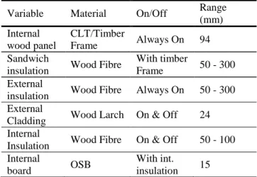
In the case of Timber Framing, an additional variable is given, which is the thickness of the sandwich insulation, which ranges between 50 and 300mm. This additional variable gives a superior strength to Timber Frame assembly method by increasing the U-value of the wall section. Table 2 shows the complete list of variable and their ranges.
Table 2: Wall variables
Variable Material On/Off Range (mm) Internal wood panel CLT/Timber Frame Always On 94 Sandwich
insulation Wood Fibre
With timber
Frame 50 - 300 External
insulation Wood Fibre Always On 50 - 300 External
Cladding Wood Larch On & Off 24 Internal
Insulation Wood Fibre On & Off 50 - 100 Internal
board OSB
With int.
insulation 15
4.2 SIMULATION AND OPTIMIZATION 4.2.1 Location & case study
In order to identify the energy consumption and weight of the given wall section, a case study has been selected for modelling and simulation. The boundary conditions of the case study have been identified based on the existing floor plans. In this research, the case study lies in the city of Brussels, the capital of Belgium. Given that roof stacking takes place on existing buildings, the middle-class pre-ware housing prototype has been selected to identify the floor plan.
The floor plan has a width of 6 meters and length of 12 meters. The height of the floor plan reaches 3 meters. Internal zones has been simplified to include 3 zones consists of 2 bedrooms and 1 service zone. The floor plan is oriented towards north south, with two row houses on the east and west facades, which consequently does not have any windows. Window ratios on the north and south are given a constant value of 20%. The characteristics of the glazing are kept constant, with a double glazing and air gap. The roof has been designed as flat roof, and given the same characteristics of the wall variations. Standard occupancy schedules for residential buildings are set according to ASHRAE.
4.2.2 Simulation & optimization method and tools
In this study, the simulation and optimization process has been carried out using Energy Plus, the energy simulation engine, using grasshopper as the interface. Grasshopper is a parametric visual programming language interface that works on Rhinoceros 3D software. The link between Grasshopper and Energy Plus is done with Honeybee and Ladybug plugins, where the geometry, simulation parameters, schedules, building materials, and results visualization are carried out.
The list of variable, as shown in Table 2, has been set in Grasshopper, and then a parametric simulation has been carried out. The parametric simulation has been run for 365 combinations of variables for the case of CLT wall section, and has been run for 2790 combination of variables for the case of Timber Frame wall section, giving a total of 3155 combination of variables. All the results has been extracted and plotted on Excel file, giving the results of energy consumption and total weight of construction. There is a lack of applying multi-objective optimization on Grasshopper; it is only possible to apply single-objective optimization using genetic algorithms. Thus, the multi-objective optimization has been carried out using Matlab, using Pareto optimization method to extract Pareto frontier.
4.2.3 Optimization results
In order to extract Pareto frontier, energy consumption and weight of construction values have been remapped, so as to give a range of values from 0 to 1. The value of 0 represents the minimum value in each of the energy consumption and weight of construction, while the value of 1 represents the highest. For the CLT wall composition, the minimum value of energy consumption was found to be equal to 16 kWh/m2.a, while the maximum value was found to be equal to 80 kWh/m2.a. Whereas the minimum value of the weight of construction was found to be equal to 175 Kg/m2, while the maximum value was found to be equal to 298 Kg/m2. The results of Timber Frame wall section were slightly different. For the Timber Frame wall composition, the minimum value of energy consumption was found to be equal to 14 kWh/m2.a, while the maximum value was found to be equal to 63 kWh/m2.a. Whereas the minimum value of the weight of construction was found to be equal to 109 Kg/m2, while the maximum value was found to be equal to 239 Kg/m2.
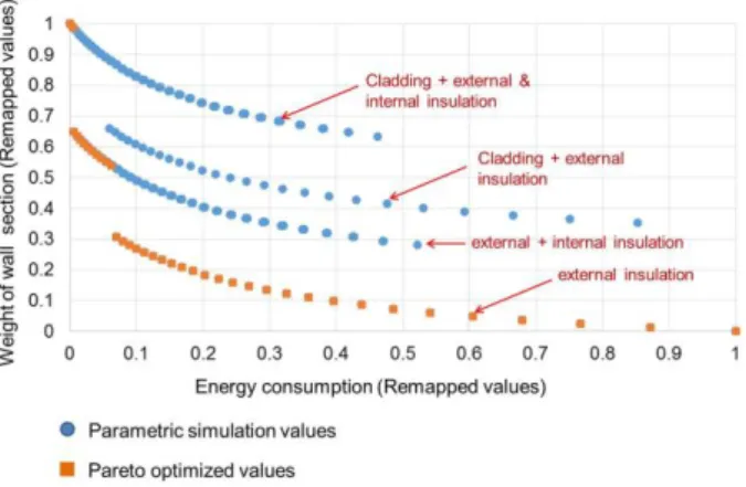
In Figures 9 & 10, the results of the parametric simulation and multi-objective optimization are illustrated. Since the combination of variables designs were set alike, the resulted curves have the same characteristics. The lowest curve on the Y-axis shows the results of the wall section with minimum composition of materials, which is external insulation only. Yet, it gives a wide range of energy saving measures, with a range of 93% (from 0.07 to 1.0 in the remapped values). Higher energy savings could be achieved by adding additional layer of insulation in the interior, while optimism savings could be achieved only by adding extra cladding with air gap. Adding external cladding to the exterior insulation does not seem to give an added value. In contrary, it adds more weight without having the benefit of saving energy compared to adding more insulation.
In figure 10, the plotted curves are doubled. This doubling is the result of the added weight by the sandwich insulation, which is negligible compared to the newly added insulation (with their additional OSB boards) on the exterior and interiors of the walls. Thus, the results do not differ that much compared to the results of the CLT wall sections.
Figure 9: Pareto frontier for CLT wall sections
Figure 10: Pareto frontier for Timber Frame wall sections
5 CONCLUSION
This article presents two important comparisons in roof stacking in general and timber construction in particular. A classification and comparative analysis has been carried out to document and list the existing roof stacking methods and used building materials. We have found that there are three different methods. The first method takes place through off-site manufacturing, producing 3D modules ready to be lifted and installed on the rooftop. The second method takes place through on-site assembling. In this method, 2D prefabricated elements, such as walls and roofs, or 1D prefabricated element, such as beams and columns, are assembled together on rooftops. In the first method of producing 3D modules, higher precision, technicality, and available supplier is a prerequisite, which tends to make it uncommon in roof stacking. Such method is only necessary in projects with tight timeframe, or busy traffic. Whereas assembling 2D and 1D prefabricated elements are used widely. Moreover, timber construction could only be used with onsite assembly. Accordingly, parametric simulation and comparative analysis have been conducted between two different methods with two different wall compositions. A wall composition of CLT material has been selected to represent the 2D assembling method, while a wall composition of Timber Frame material has been selected to represent the 1D assembling method. Two objectives have been identified for the comparative analysis. The first objective is the energy consumption, while the second objective is the total weight of construction, due to its importance when building on the rooftops.
As a result, Timber Frame has shown a superior strength compared to CLT in terms of energy savings and weight. Minimum energy consumption could be achieved using Timber Frame, which is equal to 14 kWh/m2.a with a total weight of construction equal to 239 Kg/m2. On the other hand, the minimum energy consumption that could be achieved with CLT is equal to 16 kWh/m2.a, but with a total of weight of construction equal to 298 Kg/m2. The difference in energy consumption is minor, which is equal to 14% difference. However, the difference in the total weight of construction reaches 24%, which is almost 1/4 of the weight achieved by Timber Frame. The reason behind this superiority lies in the characteristics of Timber Framing that allows the addition of insulation layer in the middle of the structural frame. In contrary, the characteristics of CLT allow only insulation to be added internally of externally, given the higher density of the CLT wall section, which exceeds its counterpart in Timber Framing. However, when the weight of construction does not represent a top priority, CLT shows higher advantages. The advantage of CLT lies in its air tightness levels, which is higher than that of Timber Frame, and affects the overall thermal and energetic performance of the building. Moreover, it lies under the advantages of 2D assembly methods, which gives higher speed and precision in construction. The choice of assembly method and wall composition is defined by the priority levels of each project separately. Accordingly, this paper aims to support the decision making process and represents a guidance for architects and practitioners to use the proper timber construction method in roof stacking projects.
ACKNOWLEDGEMENT
This research was funded by a welcome grant provided by Liege University, which are gratefully acknowledged. This publication is part of the research project 2016– 2020 entitled: DenCity Prototype: Concepts of Zero Energy Lightweight Construction Households for Urban Densification.
REFERENCES
[1] “Population Division (2015). World Population Prospects: The 2015 Revision, Key Findings and Advance Tables,” United Nations, ESA/P/WP.241, 2015.
[2] C. Bonifazi, M. Okólski, J. Schoorl, and P. Simon, Eds., International Migration in Europe : New
Trends and New Methods of Analysis. Amsterdam:
Amsterdam University Press, 2008.
[3] J. D. Marshall, “Urban Land Area and Population Growth: A New Scaling Relationship for Metropolitan Expansion,” Urban Stud., vol. 44, no. 10, pp. 1889–1904, Sep. 2007.
[4] “Population Division (2014). World Urbanization Prospects: The 2014 Revision, Highlights,” United Nations, Department of Economic and Social Affairs, ST/ESA/SER.A/352, 2014.
[5] S. Angel, J. Parent, D. L. Civco, and A. M. Blei, “The Persistent Decline in Urban Densities: Global
and Historical Evidence of ‘Sprawl,’”
ResearchGate.
[6] L. R. Hutyra, B. Yoon, J. Hepinstall-Cymerman, and M. Alberti, “Carbon consequences of land cover change and expansion of urban lands: A case study in the Seattle metropolitan region,” Landsc.
Urban Plan., vol. 103, no. 1, pp. 83–93, Oct. 2011.
[7] K. C. Seto, M. Fragkias, B. Güneralp, and M. K. Reilly, “A Meta-Analysis of Global Urban Land Expansion,” PLOS ONE, vol. 6, no. 8, p. e23777, Aug. 2011.
[8] “Urban sprawl in Europe,” EEA, 2006.
[9] A. Piorr, J. Ravetz, and I. Tosics, “Peri-urbanization in Europe; Towards European Policies to Sustain Urban-Rural Futures,” University of Copenhagen / Academic Books Life Sciences, Mar. 2011.
[10] K. Nilsson, T. Nielsen, C. Aalbers, and S. Bell, “Strategies for Sustainable Urban Development and Urban-Rural Linkages,” Mar. 2014.
[11] J. Westerink, D. Haase, A. Bauer, J. Ravetz, F. Jarrige, and C. B. E. M. Aalbers, “Dealing with sustainability trade-offs of the compact city in peri-urban planning across European city regions,” Eur.
Plan. Stud., 2012.
[12] S. Attia, “Overview and recommendation on urban densification potential in Liège, Belgium,” Jun. 2015.
[13] F. Dieleman and M. Wegener, “Compact City and Urban Sprawl,” Built Environ., vol. 30, no. 4, pp. 308–323, Dec. 2004.
[14] K. Nabielek, “Urban Densification in the Netherlands: National Spatial Policy and Empirical Research of Recent Developments,” in Global
Visions: Risks and Opportunities for the Urban Planet, National University of Singapore, 2011.
[15] “Driving and the Built Environment,” National Research Council, Washington, D.C, 2009.
[16] A. Skovbro, “Urban densification: An innovation in sustainable urban policy?,” presented at the Area based initiatives in contemporary urban policy, Copenhagen, Denmark, 2001.
[17] S. Attia, “Towards regenerative and positive impact architecture: A comparison of two net zero energy buildings,” Sustain. Cities Soc., vol. 26, pp. 393– 406, Oct. 2016.
[18] R. Ewing, K. Bartholomew, S. Winkelman, J. Walters, and D. Chen, Growing Cooler: The
Evidence on Urban Development and Climate Change. Washington, D.C: Urban Land Institute,
2008.
[19] M. G. Riera Pérez and E. Rey, “A multi-criteria approach to compare urban renewal scenarios for an existing neighborhood. Case study in Lausanne (Switzerland),” Build. Environ., vol. 65, pp. 58–70, Jul. 2013.
[20] K. Steemers, “Energy and the city: density, buildings and transport,” in in Energy and
Buildings, Volume 35, Issue, 2003, pp. 3–14.
[21] A.-F. Marique and S. Reiter, “Retrofitting the suburbs: Insulation, density, urban form and location,” Environ. Manag. Sustain. Dev., vol. 3, no. 2, Nov. 2014.
[22] D. Brownstone, “Key Relationships Between the Built Environment and VMT,” University of California, Special Report 298, 2008.
[23] R. Madlener and Y. Sunak, “Impacts of urbanization on urban structures and energy demand: What can we learn for urban energy planning and urbanization management?,” Sustain.
Cities Soc., vol. 1, no. 1, pp. 45–53, Feb. 2011.
[24] S. Lehmann, “Can rapid urbanisation ever lead to low carbon cities? The case of Shanghai in comparison to Potsdamer Platz Berlin,” Sustain.
Cities Soc., vol. 3, pp. 1–12, Jul. 2012.
[25] N. Gaitani et al., “Microclimatic analysis as a prerequisite for sustainable urbanisation: Application for an urban regeneration project for a medium size city in the greater urban agglomeration of Athens, Greece,” Sustain. Cities Soc., vol. 13, pp. 230–236, Oct. 2014.
[26] T. Attenberger, “Stadtentwicklung in Köln Lückenschluss in der Innenstadt,” 14-Aug-2014. [27] Stadt Köln, “Baulücken in Köln,” Stadt Köln, 2011.
[Online]. Available: /leben-in-koeln/planen-bauen/das-koelner-baulueckenprogramm.
[Accessed: 13-Jul-2016].
[28] S. Jaksch, A. Franke, and M. Treberspurg, “A timber based attic extension system for sustainable urban densification,” presented at the WCTE 2016 - World Conference on Timber Engineering, 2016. [29] M. Amer and S. Attia, “ROOF STACKING:
Learned Lessons from Architects,” SBD Lab, Liege University, Belgium, May 2017.
[30] K. Tichelmann and K. Groß, Wohnraumpotentiale
durch Aufstockungen. Technische Universität Darmstadt, 2016.
[31] P. Floerke, S. Weiß, L. Stein, and M. Wagner,
Typologienkatalog – Gebäudeaufstockungen.
bauforumstahl e.V, 2014.
[32] M. Lawson et al., “Review of roof-top extensions using light steel construction,” The Steel Construction Institute (SCI), 2010.
[33] J. Artés, “La Casa Por El Tejado,” 2016. [Online]. Available: http://www.lacasaporeltejado.eu/en/. [Accessed: 06-Jun-2016].
[34] G. Reinberg, “Architekturbüro Reinberg ZT GmbH,” 2001. [Online]. Available: http://www.reinberg.net/architektur/132.
[35] A. Lawrence, J. Lauppe, and T. Snelson, “Three steps to make timber a standard material for multi-storey buildings,” presented at the WCTE 2016 - World Conference on Timber Engineering, 2016. [36] M. Amer and S. Attia, “ROOF STACKING:
Learned Lessons from Architects,” SBD Lab, May 2017.
[37] C. Moran, “Raise the Roof,”