ROOF STACKING:
Learned Lessons from Architects
MOHAMED AMER
SHADY ATTIA
Sustainable Buildings Design (SBD) Lab
Urban & Environmental Engineering (UEE) Department
Faculty of Applied Sciences, Liège University
ROOF STACKING:
Learned Lessons from Architects
MOHAMED AMER
SHADY ATTIA
7
Copyright © SBD Lab 2017
ISBN 978-2-930909-03-5 All rights reserved
No part of this publication may be reproduced in any form or by any means including photocopying or any information storage retrieval system, without an official permission from the copyright holder.
Suggested Citation
Amer. M., and Attia, S., (2017) Roof Stacking: Learned Lessons from Architects. SBD Lab, Liege
University, ISBN 978-2-930909-03-5
Edition 1 (Liège | June 2017)
http://hdl.handle.net/2268/210472
Authors
Mohamed AMER, MSc IUSD Architectural Engineer & Researcher E-mail: [email protected] Shady ATTIA, PhD, LEED AP
Professor of Sustainable Architecture and Building Technology E-mail: [email protected]
Sustainable Buildings Design (SBD) Lab
Urban & Environmental Engineering Department (UEE) Faculty of Applied Sciences | Liège University (ULg) Quartier Polytech 1, Allée de la Découverte 13A B52/3 - +0/442, 4000 Liège, Belgium
Tél: 0032 4366 9569 Fax: 0032 4366 2909 www.sbd.ulg.ac.be
1
Preface
This report is a part of a PhD research project entitled “Dencity: Zero Energy Lightweight Construction for Urban Densification” carried out at Liège University, in Belgium. The project promotes for extending vertically the rooftops of existing buildings as a sustainable approach for urban densification in European cities. The project aims to develop a system that aids the decision making of Roof Stacking (R.S.) on multiple levels; urban, structural and environmental.
The presented findings and learned lessons are based foremost on interviews with architects from different European countries who have experience with R.S. projects. This report addresses architects, engineers and researchers who work on and have interest in building on the rooftops. We aim to provide the reader with insights and perspectives on contemporary construction methods and techniques used in R.S.
3
Acknowledgment
We would like to thank each of the architects by name, for giving the time and space to carry out the interviews and providing information and reflections from their experiences.
Gerardo Wadel from the La Casa por el Tejado (LCT) office in Barcelona, Spain, Georg W. Reinberg from Architekturbüro Reinberg in Vienna, Austria,
Antoine Galand from Atelier d’Architecture Galand in Brussels, Belgium
This report is a part of a research project that is funded through the Welcome Grant in science and technology of Liège University. We are grateful to acknowledge the university funding.
5
Table of Contents
1- Preface
01
2- Acknowledgment
03
3- Table of contents
05
4- List of abbreviations
07
5- Introduction
09
6- Challenges
17
7- Construction Methods
33
8- Conclusion
55
9- Annex
59
10- Questionnaire
83
11- Biography
85
7
List of abbreviations
1D Building components resembled in Columns, Beams, and frames 2D Building components resembled in Walls, Floors, and ceilings
AR Adaptive Reuse
CG Centre of Gravity CLT Cross Laminated Timber FRP Fibre Reinforced Polymers GLT Glues Laminated Timber
HVAC Heating, Ventilation and Air Conditioning LCA Life Cycle Assessment
LCT La Casa por el Tejado (architectural office in Barcelona) OSB Oriented Strand Board
R.S. Roof Stacking RC Reinforced Concrete ROI Return of Investment VMT Vehicles Miles Travelled
9
1 Introduction
In a world that faces high rate of urbanization and migrating populations towards cities, new urban agendas have emerged tackling problems related to increasing population and rapid urbanization (United Nations, 2017). As a mean to limit urban sprawl and increase urban densities, several researches explore numerous methods for urban densification with a main focus on optimizing the usage of the existing infrastructure in the cities, reducing carbon emissions and energy consumption (Dieleman & Wegener, 2004; Ewing, Bartholomew, Winkelman, Walters, & Chen, 2008; Marique & Reiter, 2014; Nabielek, 2011; National Research Council, 2009; Riera Pérez & Rey, 2013; Skovbro, 2001; Steemers, 2003; Sturm et al., 2017).
We performed a review of urban densification and recognized seven main methods to increase building density.
The first method is implemented on an individual level, by filling up the backyard of existing houses (Marique & Reiter, 2014).
The second method takes place by filling up vacant land plots between existing buildings. Those parcels could be totally vacant or occupied by ground floor shops (Attenberger, 2014; Stadt Köln, 2011).
The third method follows more intensive way by demolishing existing buildings and reconstructing higher ones (Attia, 2015; Burton, Jenks, & Williams, 2013). Fourth and fifth methods are based on the concept of Adaptive Reuse (AR). The
earlier method is applied by dividing existing multi-family houses into apartments or separate rentable rooms to accommodate more inhabitants, while the later concerns changing the usage of existing structures (not particularly houses), such as old factories and office buildings, into residential buildings (Shipley, Utz, & Parsons, 2006).
The last methods, sixth and seventh, focus on the usage of existing residential buildings rooftops. It is either limited to transforming old attics used as storages into inhabitable ones (Floerke, Weiß, Stein, & Wagner, 2014; Tichelmann & Groß, 2016), or by building additional stories over the rooftop (Amer, Mustafa, Teller, Attia, & Reiter, 2017; Attia, 2015), which is aforementioned as Roof Stacking (R.S.).
11 filling backyard infill development house re-division building reusing
demolish & rebuild attic exchange roof stacking
Building on the rooftops has multiple advantages as an approach towards urban densification. Building on the rooftops preserve the morphological and architectural identity of existing buildings and urban landscape (Nilsson, Nielsen, Aalbers, & Bell, 2014), not to mention the opportunity of using possible financial benefits into retrofitting existing old buildings. On the individual scale, several R.S. projects took place as a way to increase livable residential spaces in cities that suffer from scarce empty land plots. On the national or regional scale, it has a potential to provide accommodation for increasing population in the major cities. R.S. is seen as an approach towards urban densification as well as financial revenue for house owners, and an opportunity to find room for inhabitants. Moreover, R.S. has become an important topic that is being addressed with an aim to provide solutions and feasible means for implementation and replication.
This report aims to present a guideline for R.S. construction methods that has been used by architects from different European countries who have experience in R.S. projects. Three main objectives were set for this report; first, identifying the obstacles and challenges accompanying roof stacking projects. Second, presenting practical construction solutions and methods used to solve the problems associated with roof stacking projects. Third, validate and create a classification for construction methods that are used for this type of projects. Case studies of R.S. projects have been investigated in depth through interviewing architects who were responsible of the design and construction team in charge of project implementation. Based on semi-structured interviews, a questionnaire consists of 7 main questions [see the Annexe] was designed and the interview was carried out with architects. The architects were encouraged to provide additional information apart from the questionnaire. The additional information was later included and reorganized to fit in to the designed questions.
The interviews were conducted individually with three architects in three different countries. They are arranged chronologically as following:
Gerardo Wadel, the director of the Research and Development department at “La Casa por el Tejado” or LCT office in Barcelona, Spain.
Georg Wolfgang Reinberg, the owner and director of “Architekturbüro Reinberg” in Vienna, Austria.
Antoine Galand, founding partner of “Atelier d’Architecture Galand” in Brussels, Belgium.
13 Each interview has been recorded using an audio recorder after taking the permission from the architect. Then, the interviews were written and attached in the annex attached to this report [see annex]. The architects were selected based on their different construction methods used in R.S. Each construction method has been documented and classified within in a holistic classification that has been developed in this report. Based on the classification, a comparative analysis is carried out. Recommendations, benefits and drawbacks are given accordingly for each R.S. construction method.
In depth analysis is carried out for the case studies. The analysis is based on literature review, and from the architects’ experience on each case study. Throughout the analysis, it was found that it is difficult to create a unified system to apply roof stacking broadly. Urban, structural and administrative contexts are unique for every case. However, there is an outline that identify common criteria that affect the decision making when applying a R.S. projects. The criteria are categorized under six main categories as following:
Cost Time Safety Quality Environmental Logistical
It is important to mention that the report focuses mainly on the technical aspects of R.S. projects. The considerations related to urban regulations, infrastructure, mobility, and the broader vision of social acceptability are slightly investigated, but not focused on. This report does not aim to promote for through roof stacking as the ultimate solution for accommodating increasing population. The report provides an overview for professionals, who work in the building industry sector, with the common challenges of R.S. in cities. In addition, the report provides several means and solutions to overcome those challenges through learned lessons from experienced architects in that field.
The report is divided into five main sections. The first section includes an introduction to R.S. projects while shedding the light on urban densification. The second section presents the most common challenges of roof stacking and practical solutions for each challenge. The third section presents different methods of R.S. construction. Those methods are categorized under load bearing and installation techniques. The fourth presents an overview on the advantages and disadvantages of roof stacking from the point of view of the architects. The fifth and last section concludes the learned lessons from the architects. The report is annexed with a copy of the questionnaire and the extensive interviews results that has been carried out with each of the architects.
17
2 Roof stacking challenges
Building on rooftops is entirely different from building on the ground. Several considerations have to be taken. The challenges that face R.S. projects have been listed and categorized into 5 types as following:
Building constructional Building services Administrative & social Financial
Lightweight building materials
In the following section, we discuss each challenge more briefly. We additionally provide possible solutions as a mean to overcome each challenge from the practical point.
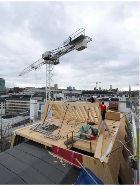
Figure 1: Sleep well in the sky hostel Project, Brussels, Belgium © Atelier d’Architecture Galand
19 [1] Building constructional Challenges
The actual strength of the existing building
The first question that should be asked is whether the existing building is capable of holding additional structure or not. It is possible to determine the strength of the existing building either by theoretical calculations or through deep investigations. Theoretical calculation requires possessing the technical data of the building, starting from the specifications of the used buildings materials to the type of foundation and soil.
The second method is applied by investigating the existing structure through multiple techniques used by specialized civil engineers. Among those techniques are the visual inspection using thermal cameras and Geo-radar tools. Other techniques use destructive investigations that requires taking samples from the existing structure to be tested. This type of investigation is necessary for aged buildings, because the structure of the old buildings has the tendency of changing its behaviour throughout the years. For instance, some walls that were not designed initially as shear walls could end up bearing weight due to the natural movements taking place in the soil and within the entire building. Through deep investigation, those types of alteration could be detected and further internal reinforcements could be applied when needed.
Foundation strength and soil allowable bearing capacity
The second challenge lies in the type of foundations and whether they are sufficient to hold a new structure. The same methods used to identify the actual strength of the existing building are used for the foundations. It is important to mention that the capacity of the soil and foundation to bear additional weight changes due to earth movements and the consequences of soil compression throughout the years. In real cases, the soil surrounding the foundation is dig up to be inspected together with the foundations, and extra reinforcement is added to the existing foundations when needed.
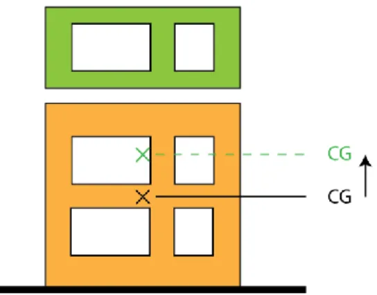
Earthquakes and centre of gravity
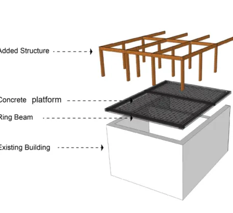
Two main aspects related to earthquakes should be taken in considerations when adding more floors on the rooftops. The first aspect concerns existing building’s centre of gravity (CG). As the height of an existing building increases, its CG gets higher consequently as shown in Figure 2. Thus, it is important to recalculate the structure of the whole building and take safety factors in consideration. The second aspect is concerned with old building’s structural configurations. The majority of existing buildings that were built before the First World War were not designed to resist earthquakes. By adding an additional weight, existing building becomes more vulnerable to seismic forces.
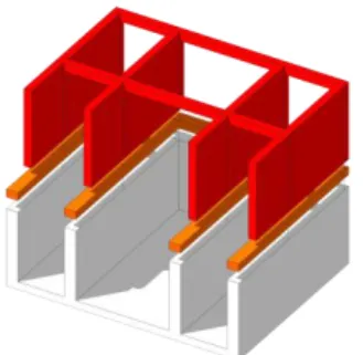
21 Several methods are used to increase the strength of existing buildings against earthquakes. One practical method is proposed in this report. That method suggests adding a ring beam on the shear walls of the existing buildings as shown in Figure 3. The ring beam is made of reinforced concrete (RC) that provide additional tensile strength to the masonry walls. That method works for both existing building and added floors, in which the ring beam acts as a roof anchoring to the new extension. In some cases, when the existing building is capable of holding more weight, a reinforced concrete (RC) platform can be added to the ring beams.
Structural calculation of the extension
Structural calculations of added floors differ from conventional unground calculations. This difference occur for several reasons. One reason is due to the nature of the added structure, which has to consider strict load distribution that follows the structural configurations of the existing structure. Another reason is related to the lifting process of the structural components. Whether the lifter components are 3D units, as shown in Figure 4, or 2D walls and slabs components, those components should be designed to resist counter forces of tension and compression. Thus, calculations has to take in consideration both, loads behaviour under normal circumstances and lifting process.
Transportation, lifting and installation
The majority of roof stacking projects take place in the context of occupied cities. This context requires a speed in transportation, lifting and installation of building components. Street widths, crane’s capacity and the weight of building components are all taken in consideration (Olearczyk, Bouferguène, Al-Hussein, & Hermann, 2014). For instance, street width and available cranes will affect the dimensions of prefabricated building components. These dimensions are considered a restriction for the architect during the early and late design phases of the project.
23 Figure 4: Housing project by LCT in Girona, Spain.
[2] Building services
HVAC – Heating ventilation and air conditioning
A multiple challenges are included when it comes to Integrating active systems in both the new extension and the old building. In most cases with old buildings, existing HVAC systems do not function efficiently. By adding more stories, it makes it nearly impossible for the existing HVAC system to cover the newly required capacity of the whole building. In this case, one of two solutions could be proposed. Either a total renovation has to be carried out for the whole system to increase its efficiency, or a new active system could be replaced of integrated to the existing one as shown in Figure 5.
Water, plumbing & electricity
Within the surveyed cases, there is a minor challenge associated with integrating or adding extensions to water, plumbing and electricity. However, it has to be taken in consideration within the design phase to apply modifications or additions when needed.
Figure 5: Residential building project in Kierling, Austria © Architekturbüro Reinberg
25 [3] Administrative & Social acceptability
Urban regulations
Local urban regulations are always concerned with allowable maximum height, which represents a restriction for applying R.S. projects. There are two ways to calculate allowable maximum height. The first way is related to the maximum height of neighbouring buildings or the average buildings height of the same street. The second way is related to the right to light, which means that the maximum height shouldn’t affect reduce the amount of daylighting received by neighbouring buildings. Even though when buildings’ strength could bear additional load, they have to comply with urban regulations.
Other restrictions are related to getting approval from the city administration that is concerned with the conservation of city’s architecture. Other parameters are taken in consideration that are related to urban environment, social justice and fair distribution of neighbourhood densities. These parameters aim to maintain sustainable living environment in terms of open spaces, adequate population, and transportation.
Social acceptance
Social acceptance represents one of the main restrictions when deciding on proposing interventions in the surrounding urban context in general, and R.S in particular. What is meant by social acceptance in this context is the acceptance of building’s owner and surrounding neighbours. Since the construction process is associated with noise, inconvenience and general discomfort to the neighbours, an approval from existing community associations and neighbours has to be granted prior to the construction process. Sometimes neighbours represented in community associations have to be involved within the design phases.
[4] Finance
Financing R.S. projects in this report is discussed under two aspects. The first aspect is related to finance associated with construction method. Based on the conditions of the existing building and its surrounding, construction method would differ from one project to the other. There are some factors that affects the overall cost of each construction method. Those factors are counted as following:
Operational cost (tasks and deliverables on and offsite) Labour cost (working labours, supervisors, site managers, etc.) Material cost (building materials used on and offsite)
Transportation cost (transporting materials to the site and loading on the rooftop) Maintenance cost (defects and damages onsite)
The cost of each factor differs from one construction method to another. More details about the methods of contemporary construction for R.S. projects is discussed in the sixth section of this report.
The second aspect is concerned with the financial revenue of R.S. projects. From the theoretical point of view as well as the practical one, R.S. projects are considered to be financially successful option. However, the first aspect that is related to cost method and construction should be carefully taken in to account. The overall return of investment (ROI) takes into account the cost of construction, rental price, and potential renovation of the existing building in terms of energy consumption and energy supply.
[5] Lightweight building materials
There are several criteria that affect the choice of building materials generally. In R.S. projects, the choice of lightweight building materials is essential. Accordingly, five main challenging factors were found when choosing lightweight building materials, which are shown as following:
27 Weight vs mechanical properties
Additional weight on the rooftop is considered to be a core concern when working on R.S. projects. Added weight counts the sum of dead loads, live, wind, snow, and variable loads. Given that the live, wind, snow and variable loads are constant in any added structure, dead loads are only remained for optimization. In other words, the lighter the better. However, the lighter building materials are, the poorer their mechanical properties. Steel and timber are used widely to build up the substructure of R.S. projects. The substructure is defined as the assembly of the several building components such as beams, columns, and frames. Even though steel has higher density, which is equivalent to 8,050 kg/m3 compared to 1,100 kg/m3 as the maximum density for ebony timber, steel is considered a better option in many cases. This advantage returns back to the achievable high tensile strength of steel sections without increasing their cross section, which will produce an overall lighter construction. This advantage is used when covering long spans structure. While using timber to cover long spans will require larger cross sections and consequently heavier weight.
In case of using prefabricated subsystem components, such as walls, floors and ceilings, timber is used widely. There are several types of prefabricated timber subsystems, such as CLT (Cross Laminated Timber), GLT (Glued Laminated Timber), OSB (Oriented Strand Board), Plywood, etc. Even though those components have great advantages in reducing the overall carbon emissions of the building and containing less embodied energy, they have disadvantages when it comes to acoustic performance and overall weight. Thus, in many R.S. cases, both timber and steel are used together in construction, taking the advantage of both materials.
Fire resistance
In fire resistance regulations, buildings are categorized based on their height and function. For instance, with the example of height:
Low-rise: height less than 10 meters Mid-rise: height between 10 and 25 meters High-rise: height more than 25 meters
For each category, a minimum performance of building materials is required. This performance define the tendency of building materials to react with fire. In Europe, there are seven classes for building materials as following: A1, A2, B, C, D, E and F defined by EN 13501-1. For instance, building materials that lie under class A1 are non-combustible, while building materials that lie under class E are those that contribute to fire in the first 2 minutes of localised fire before flash-over.
As mentioned previously, using lightweight materials is inevitable when building on the rooftops. However, lightweight materials are vulnerable to fire in different forms. For instance, when comparing the reaction of timber and steel, each material reacts differently with fire. Timber is categorized as flammable material, which increases the combustion rate but does not lose its mechanical properties. While steel is inflammable, steel loses its mechanical properties with fire.
Multidisciplinary aspects are followed in fire safety engineering. Those aspects are divided into three strategies: preventions, active protection, and passive protection. Prevention focuses on choosing adequate materials, safe electric installation, and training for evacuation. Active protection focuses on installing active systems in buildings such as early smoke detection, alarm, automatic extinction, and smoke extraction. Passive protection deals with design aspects, such as compartmentalization of interior spaces and the structural fire resistance design.
29 Acoustics
One of the very common drawbacks of using lightweight materials is their acoustic performance. There are two main challenges when dealing with acoustic impedance of building materials. The first challenge deals with sound pressure that transfers from one space to another. This occur most commonly on a horizontal level between internal rooms together, and internal room with the exterior. There are several steps to optimize the performance of sound impedance of lightweight building materials.
Creating double layer wall
Separate both layers with sound insulation Increases the cavity between two layers
Reduce sound bridges formed by studs connecting both layers
The second challenge occurs on a vertical level. This challenge only takes place when building more than one floor over the rooftop using lightweight materials. Therefore, materials used to construct ceilings and floors should be treated differently from those used for walls. When considering another building material such as concrete, it has better acoustic impedance; however it is associated with much heavier weight. Thus, choice of building materials is required during the early stages of roof stacking design considering multi-objective approach.
Thermal performance
Two main concerns are associated with the thermal performance of lightweight building materials: thermal resistance and thermal mass. Thermal resistance is the tendency of the material to resist heat transfer from one side to another through convection. Lightweight building materials such as timber and steel have poor thermal resistance values. For example plywood with a thickness of 90 mm has R value equivalent to 1.0 m2K/W compared to insulation materials such as rock wool with the same thickness
which is equivalent to 4.09 m2K/W. Therefore, using insulation materials are inevitable
when designing wall sections for R.S. buildings.
The second concern is related to thermal mass, which is the ability of a material to absorb and store heat. Thermal mass is essential in regulating temperature between the indoor and outdoor during day and night. This problem may cause overheating risk during summer in hot and moderate climates. Passive solutions, such as automated shading devices, high thermal mass and reflective rendering materials, etc., could be used to reduce but not eliminating that risk. Therefore, highly efficient HVAC system is essential to prevent overheating risks and secure indoor constant thermal comfort during the whole year.
33
3 Roof Stacking Construction Methods
Over 60 case studies of R.S. projects around Europe have been investigated and a classification for R.S. construction techniques has been carried out. The Classification has been further refined based on the results from the interviews with the architects. Construction methods of R.S. are divided into two sections:
Load bearing methods Installation methods
Methods of load bearing methods are meant to describe the means of load distribution on existing buildings. Several methods of load bearing were found to be used in R.S. projects, which will be explained in details. Whereas methods of installation are concerned with the way of transporting, lifting and assembling the additional floors. All R.S. projects found in literature have used prefabricated building components. More details are explained in the next sections of this report.
Two versions of classification have been developed. The first version was given to the interviewees for reflection and validation. While the second version has been formulated according to their feedback on how things are preceded in real life. In the outcome section of this report, the reflections will be directed to the newer version of the classification for better understanding.
[1] Load bearing methods
Load bearing methods are the approaches of bearing additional loads on existing buildings. Two main methods of load bearing were found, where the actual strength of the existing building and structural configuration play an important role in the decision making process. The first method is direct bearing on existing structure. The second method is bearing with additional reinforcement. Multiple methods could be used in one project. A case study made by Atelier d’Architecture Galand is described in details [see Annex]. In that case study, additional floor was added on two different buildings with two different structural configurations.
Load bearing on existing structure
Most of the projects are built on existing buildings that date back to the 19th century.
R.S. projects counted on the structural strength of the existing buildings to bear the loads coming from the new extension. Two ways of load bearing are found under this method. The first way is a direct bearing with a total respect of the structural configuration of the existing building. The second way is an indirect bearing through load transformation system or platform.
35 Figure 6: load bearing of roof structure
(A) Direct load bearing
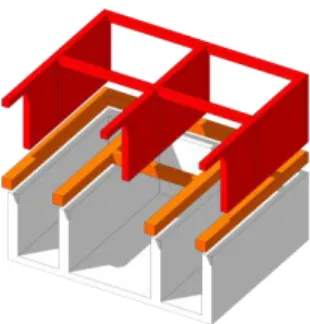
Direct load bearing respects the structure of the existing building. Added structure could be applied either parallel or perpendicular to the existing structure. Perpendicularly added structure is only obtained by adding 2D subassembly building components only as shown in Figures 6 and 7. Wall panels act consequently as new bearing walls for additional floors. In one project, both ways could be used according to the new extension’s required design.
Applying direct load on the existing structure requires a ring beam as a prerequisite as shown in Figure 8. This ring beam is located on the bearing walls of the existing building as transition elements between the new and old structures. For skeleton or concrete structures, direct bearing could be applied directly without ring beams.
Figure 7: Direct bearing parallel to structure
Figure 8: Direct bearing perpendicular to structure
37 Figure 9: Using 2D subsystem building components as bearing panels. Those panels may rest
(B) In-direct load bearing
In-direct load bearing method has been used in the majority of the review case studies. This method requires a load transferring system. This system is composed of a ring beam made of RC that bundles bearing walls together and steel beams grid that is designed to receive loads from the added extension as shown in Figure 10.
Load transforming system can be substituted with a load transforming platform or level, which is well known as “Lastverteilungsgeschosse” in the German as shown in Figure 9. Even though such a platform adds more weight on existing building, it provides higher design flexibility for the additional floors.
39 Figure 11 is taken from La Casa por el Tejado (LCT) office in Barcelona. LCT office represents a live case study for a R.S. project using this indirect load bearing techniques through loads transforming system.
Figure 12: Live cross section from LCT office in Barcelona
More illustrations that explain in-direct load bearing methods are shown in Figures 12 and 13. The ring beam and (red) steel beams represented in Figure 13 represents the ring beam and (white) steel beams shown in Figure 11. Whereas the concrete platform shown in Figure 12 represents the sketch drawn by the architect Reinberg [see Figure D in the Annex]. Concrete platform has also been used in other case studies which have been reviewed from the literature (Tichelmann & Groß, 2016).
41 Figure 14: Using main building components resembled in the columns and beams in the new extension. An opportunity of making a recess from the buildings boarder for terrace
Load bearing with additional Reinforcement
Additional reinforcement was found to be applied on two different levels. The first level is applying minor reinforcement tor some elements of the existing buildings, those who have been deteriorated or altered their structural performance throughout the years. The second level is major reinforcement for foundations, soil or additional columns and beams stand from the ground level to the new extension. These types of bearing methods are costly. However, they are applied for buildings with irreplaceable location or function.
Types of additional reinforcements
There are multiple techniques of reinforcement that are being used (Papageorgiou, 2016). Each technique is used according to the element that is required to be reinforced.
1- Fibre reinforced polymers (FRP) for columns, beams, slabs & walls 2- Concrete jacket with additional reinforcement for columns, beams & walls 3- Steel jacket technique for concrete columns
4- Bonded Steel elements for slabs 5- Externally bonded steel strips for walls
43 [2] Installation methods
Based on the interview results, some modifications related to the installation techniques have been carried out. Three main methods of installation were found to be used in R.S. projects. Installation methods in this report describe the level of prefabricated building component used in R.S.
Assembly of 3D modules
Building elements are assembled offsite to form complete or partial 3D modules as shown in Figure 14. Those modules are transferred to the site, lifted and installed on the rooftop of existing buildings. Such method of manufacturing and installation requires a full coordination and integration between the designer and the manufacturer. Moreover, it is highly important to have a reliable manufacturing company that provides such service.
3D modules or semi-modules assembly requires high quality off-site manufacturer. Exceptional cranes and specialists take the responsibility of transporting and lifting up the modules on the rooftop ash shown in Figure 15, while the rest of the crew takes the responsibility of locating the lifted modules precisely on the rooftop. According to the LCT office in Barcelona, streets’ widths of Eixample district allow manufactured modules to reach up to 22 meters long. This method has several advantages in terms of reducing the amount of time needed onsite for transporting materials, lifting and occupying the street and the building. It is relatively the fastest method among all the categorized methods. However, this method needs special conditions and facilities such as suitable urban context, availability of a reliable manufacturer and skilled labours. One complete floor can be lifted up and assembled in a range of one up to three days depending on the size of the project.
Sufficient amount of time is needed for preparing the rooftop before transporting and installing the 3D modules. This time is also needed for manufacturing the modules in factory as shown in Figure 16. The preparation process includes removing extra items on the rooftop and installing the structural platform that will receive the 3D modules. Another amount of time is needed after installation to finalize interior spaces and facades. The finalization process takes around three months, depending on the size of the added floor.
45 Figure 16: Lifting 3D modules over the rooftop in Barcelona
© La Casa por el Tejado
Figure 17: Offsite 3D modules manufacturing at Mothership, Barcelona © La Casa por el Tejado
Assembly of 2D subsystem components
The general constructional hierarchy consists of several levels of building items. A subsystem is the load bearing constructional item that lies between a substructure (such as building skeleton) or building component (such as beams and columns), and the final building. In R.S. projects, 2D subsystem components are manufactured offsite. Those components are manufactured as walls, floors, and ceilings to form building envelope and internal partitions as shown in the illustration of Figure 17. 2D components are made of timber in different forms such as CLT (Cross Laminated Timber) as shown in Figures 18 and 19, GLT (Glued Laminated Timber), OSB (Oriented Strand Board), Plywood, etc.
Lifting 2D subsystem components does not require heavy cranes compared to lifting 3D modules over rooftops. However, assembling 2D components takes more time than assembling 3D modules. In both cases, a high level of precision is required when designing and fabricating 2D components.
47 Figure 19: 2D plywood assembly early phase, Kierling, Austria
© Architekturbüro Reinberg
Figure 20: 2D plywood panels assembly late phase, Kierling, Austria © Architekturbüro Reinberg
Assembly of 1D building components
The 1D building components refers to beams, columns and assembly groups of frames or bracings as shown in the illustration of Figure 20. Those components are prefabricated and delivered for onsite assembly. This method of installation takes more time than the other two methods (3D and 2D assembly). Therefore, assembling 1D building components requires neighbours acceptance, space and time.
In one of the investigated projects done by Atelier d’Architecture Galand as shown in Figures 21 and 22, the courtyard of the project was used for loading building components, assembling, and then lifting the assembly groups of walls and frames up to the rooftop as a fragmented building envelope. In that project, the existing roof was functioning during the construction process before they switched its function to the new one, which was one of the main reasons of choosing this method in construction.
49 Figure 22: 1D timber elements assembly early phase, Brussels, Belgium
© Atelier d’Architecture Galand
Figure 23: 1D timber elements assembly late phase, Brussels, Belgium © Atelier d’Architecture Galand
[3] Discussion
Nowadays, several approaches are being proposed for urban densification from multiple perspectives such as regional development, urban planning, ecology, mobility, finance, social acceptability and architecture. In this report, we aimed to portray a holistic synopsis on roof stacking as an approach for sustainable and efficient urban densification. Several notions have been tackled in this report that occupies the platform of construction sector in Europe. Those notions include but not limited to of offsite construction, modularity, building renovation, lightweight and timber construction.
Roof stacking is a part of a building story. It has been witnessed and practiced since ages for several reasons. Nowadays, it has been an increasing phenomenon that acquires a sense of urgency rather than a luxury on the urban and regional level. However, we found no systematic approach that promotes for roof stacking on the urban, constructional and social level. Accordingly, and as a part of an ongoing research, we aim to realize a systematic framework for roof stacking that identify and classify roof stacking construction methods from different outlooks as a first step towards aiding an informative decision making process. Throughout the interviews and the investigated case studies, it was a challenging task to create a unified method for roof stacking whether from a constructional or architectural perspective. Each project has different challenges that need to be tackled individually and simultaneously. Yet, it was possible to list and further categorize those methods.
A classification has been carried out based on over 60 investigated R.S. projects around Europe as shown in Figures 23 and 24. Later modifications took place after interviewing the architects and have been presented in this report. Throughout the interviews and the investigated case studies, it was a challenging task to create a unified method for roof stacking whether from a constructional or architectural perspective. Each project has different challenges that need to be tackled individually and simultaneously.
51 Figure 24: Load bearing methods classification
53 This, the main interpretation of this report lies in dividing R.S classification into two branches: load bearing and installation methods. This division helps identifying the factors and motives of choosing one construction method from another, which has been discussed in brief under each method. The analysis provides further criticism on each method as a first step towards developing criteria that aids the decision making process of R.S. construction methods.
The focus of this report is on low and mid-rise residential use buildings (not more than 25 meters height). The majority of the investigated precedents had additional 1 to 2 stories. The investigation was followed by interviews with architects who have experience with R.S. projects. The aim of the conducted interviews is to give in-depth overview on constructional aspects of R.S. projects and to validate the developed classification. Each of the architects was able to identify certain method of construction through the given illustrations as shown in Figures 23 and 24.
55
4 Conclusion
Two main points of strength characterize the results of this report. The first point lies in the context of study. Investigated case studies were chosen from multiple locations around Europe, and the interviewed architects have been selected from three different countries. The second point of strength is related to the development of a new classification for R.S. construction methods. The classification is divided into two main categories, which are load bearing and installation. This division helps identifying the factors affecting the decision making on choosing certain construction method. Throughout the investigation, six main factors were found to affect the decision making on R.S. installation methods, which are cost, time, quality, safety, environmental impact and logistics.
However, the developed classification and defined criteria are limited to the structural aspects of R.S. There were no mathematical models or calculation that took place in that phase, knowing that it is inevitable to conduct full structural analysis of the existing building and the new extension. We suppose that calculation phase are done in later phases of project design and should solely be done by specialists. The results of this report aim to support the decision making on the construction method in the early design phases. Every single project requires exclusive innovative approach to counter onsite problems. Lastly, we are aware that the number of conducted interviews are not representative. This report follows a qualitative approach of investigation, and that possible onsite problems and solutions would lie within the suggested methods on the abstract level.
This report is a first step towards support the decision making for R.S. projects around Europe. Thus, more investigation and interviews are recommended as a mean to strengthen the analysis results, in addition to giving more detailed constructional details and applications.
59
ANNEXES
FIRST INTERVIEW
Place: La Casa por el Tejado (LCT) Office in Barcelona, Spain Date & Time: Wednesday 1st of March 2017 @ 16:30
Interviewee: Gerardo Wadel, Director of Research & Development Department at LCT and Co-founder of Societat Orgànica
MA: Why do you find roof stacking a good solution for urban densification? GW: In Spain, the urban spaces has been growing between the 19th century and the 21st.
The ecological foot print has increased by 40% with all the occupied spaces in its entire life. Therefore, this created a type of a city seen just as a room to sleep in. The environmental and social perspective, such as having the access to cultural locations and services, have faded away. Earlier, there were some experiences with vertical extensions here in the city before “La Casa Por El Tejado” has started, which raised the question whether it is possible to find land on the rooftops and offer additional houses in the in the Eixample district in Barcelona. Earlier studies were made by LCT found more than 2,800 buildings with the potential to build on their rooftops (Moran, 2015), and 4,000 in whole Spain (this is only according to LCT primary investigations). Another study that was made by APUR showed that 12% of the parcels in Paris has the potential to be vertically raised (Alba et al., 2014).
MA: According to the given illustrations, which method do you usually use in your projects?
GW: Those illustrations are very interesting and allow you to understand quickly the different ways to do this process, we can identify exactly what is our way! Our method of construction and load bearing aligns with A1 technique. More specifically similar to A1.2, which resembles bearing the loads though a load transforming system (a frame of load distributing system) that is composed of concrete beam along the exterior walls of the old buildings with crossing steel beams. Figure 4 is taken from LCT office in Barcelona, which
61 shows a live cross section for the load transforming system through ring concrete beam in grey and the white steel frames that connects the old building with the new one. However, we never used the A1.1 method because we do not use 2D linear elements in the construction such as beams and columns that has the tendency to connect from wall to wall. Instead, we build full modules that are built on one century old building that needs an interface where the new loads can be freely distributed.
Generally, the illustration represents a wide part of possible techniques that can be used. In our case, if we are working in another context different from that in Eixample in Barcelona, it would have been very different. We can assure now based on our experience of 10 projects, there is one case where we have to reinforce the existing structure. That case had an open ground floor due to the commercial use, where there are four or six columns made of old steel and the receiving the building loads which arrives from the beams and concentrated on the columns to the soil. And it was a very strange and unusual case for the transition of the loads, we consider this columns are not capable to receive an overload. By practice, we never did additional reinforcement to any of our projects before. However, there was only one case under investigation in Buenos Aires, where it had two stories and wanted to be extended up to six stories. In that case our studies showed that a new independent foundation has to be made to make it possible. According to the installation techniques graph, we use the onsite assembly of prefabricated units (B1.1), where the modules arrives onsite 80% finished. But applying the installations, windows, façade finishing and the upper part of the roof renewable energy appliances were constructed using the hybrid method (B2.1). On the other hand, the method of assembling prefabricated elements (B1.2) arrives on site 40% finishes, and it requires a lot of time to be finished onsite. In our prefabricated units’ assembly method (B1.1), we use the crane within a very short time, because it cuts the circulation of the cars and transportation system, where the local government gives only permissions on Sundays in case of Barcelona. Therefore, time, weather, comfort aspects and lighting are very important to be adjusted and secured when constructing onsite. Therefore preparing
the modules in the factory resembles the perfect solution for that case. In addition to the fact that we are working in a part of the city that suits very much that method, we have wide streets to move a crane and transport a module that can reach up to 22 meters long. MA: How could you secure the structural stability of the whole building?
GW: We made a brief explanation on how the data and the values of the walls and bearing capacity are extracted in several publications. (Artes, Volpi, Wadel, & Marti, 2016; Artes, Wadel, & Marti, 2017). The foundation of the “Eixample” area is made of cross cutting integrated walls that are not independent. This type of building have walls separated with 3 or 4 meters that makes a grid in two directions and they work together. The walls are made of handmade bricks, while the foundations are 2 meters deep made of the same bricks in addition to stones or the rest of construction works. If the walls in the ground floor is 30 cm width, the foundation system is estimated to be from 45 or 60 cm width. The first step is to calculate the strength of the masonry walls. To make this calculation you may need to cut a part of the wall and measure in the laboratory. Sometimes the lab measurements are bigger than the calculated ones. Therefore, we use the measurements that comes from the laboratory, in addition to the coefficient of security to comply with the construction standards. The second part is through investigating the foundation of the existing building and know their specifications in terms of dimensions, material type, state of conservation, etc. Third, we determine the tension of the soil under the foundation system. Those are categorized under the destructive analyses. For non-destructive analysis methods, we use some tools that helps us in the investigation such as the Geo-radar that determines the densities of the materials and approximately determine the strength of the structure. Another tool is the video cameras with a wire that inspect cavity walls or spaces that are not accessible without making destructive analysis. Accordingly, we recalculate the actual strength of the existing building under investigation.
From a structural point of view we have to highlight one important point that is related to using the crane to lift the module on the top of the building. The structural forces are absolutely different when compared to the normal case. This is very important issue that
63 has to be taken in consideration when making the structural design because a module that is developed to support vertical forces and loads is different from a module is designed to be pulled by a crane from 4, 6 or 8 points.
MA: On which bases do you choose the building materials?
GW: One of our main goals when creating that system is to make designs for light weight modules. The current modules weigh around 330 kg/m2 and this is the third part of the
current system that we have now made in situ with bricks, concrete and mortar. We are in the process of developing a new building system between 250 - 300 kg/m2. It may seem
to be a small difference, however it makes a big difference with multiple units. Some buildings have strict load bearing capacity, which require a very light weight building system to be possible to make this extension.
In LCT, we form the flooring slab by using a sheet of cold-formed steel with a layer of concrete. The steel is used for the tensile forces while the concrete is basically for acoustic and fire protection. It is very similar to the combination of steel and concrete in contemporary buildings. The slab can also be made out of timber mainly for three reasons; first, because it reduces the time needed to form the slab. Second, it is lighter. Third, it has lower embodied energy and CO2 emissions. However, using timber instead of concrete is accompanied by an additional cost of 50 euros per square meter.
Senda is a new tool that has been used in LCT and developed specifically for environmental aspects of the building sector and according to our experience with the local energy certification. In Spain, there is an obligation to make energy simulation to the building with a dynamic tool. Every project has to be compared with a reference building, which is a building with the same boundary conditions complying with the minimum requirements. In order to achieve the certification, we have to make modifications on that project to reduce its energy demand.
There is the official one called HULC “Herramienta unificada LIDER-CALENER”, it can be roughly translated as the unified tool for energy demand limitation and qualification. In one
hand, you have the energy demand and on the other hand you have the energy study of your project.
For example, in our research and development department, we have a focus on solving the possible problems associated with thermal bridges resulted from using steel frame for the module’s skeleton by using timber instead of steel for instance, in addition to the price, time of construction in factory, thermal quality, and infiltration that are highly taken in consideration.
MA: How could you integrate the existing building services with the new extension? GW: According to our experience this is not a big problem. Regarding the electricity, in some cases you only need new extensions to and connections to the city grid. Regarding the sewage and piping, it is still useful to make only an extension without any additional system. However, in some cases, the old system has to be replaced or maintained to prevent future problems. The main challenge is usually concerning installing an elevator in a house because it is a very complex operation that may disturb the vertical circulation of the building, and there may be no place for a lift, so may need to cut part of the stairs or using the courtyard of the building. We had one case where it was impossible to install a lift because we didn’t arrive to an agreement with the local government related to dimensioning of the elevator, therefore we had to abandon the project. However, extending the stairs is not a big problem. To extend the stairs is not a big problem. In some cases we need to refine its geometry starting from the last existing floor, because the size between two stories could be different as you need to correspond to the height of the neighbouring buildings to combine the old with the new part of the building, so this is a process with new approximations with old, new, neighbouring buildings, etc. Briefly, the main problem is with the dimensioning and geometry but not with the process of the system itself.
65 MA: What are the most common social or legislative obstacles that you face? GW: However, making calculations, prefabrication in the factory, transport them on to the rooftop and applying finishing may sound complicated, it does not resemble a big problem or disadvantage. What stands against Roof Stacking is that it is a very long process especially when it comes to the obligation of making agreement with a lot of people. Due to the lack of experience from technicians, neighbours and citizen, the process faces more obstacles specifically with the lack of specific construction and urban standards for this special type of housing. In some cases, people think that this is an illegal process and it is associated with a lot of risks and with minor advantages. However, the addition of more stories is considered to be a part of the story of architecture and it is not something new. In addition, some buildings have a lot of problems that should be fixed prior to initiating an additional floor, which is considered as a part of the whole process. Sometimes it is too expensive that it wouldn’t be feasible even after a successful rental or selling of the new flats. There are many limitations that hinders roof stacking basically within the current urban standards in how to calculate the maximum height, volume or area that you are allowed to build within. For example, if a window is opened towards a neighbouring building, this resembles a restriction to that building to be raised by the fact of that there is a window opened on that side. After fulfilling the urban and regulative standards, the load bearing capacity of the existing building comes in the second phase. We kept in mind if that building is interesting to offer an amount of money to buy that right. Other things like legal aspects and urban standards, you can find up to 20 people with a right of property, so we need a lot of time and effort to make an agreement with all those people with different interests, ambitions, relationships and fears which are not sure for them, such as risk of collapse and security.
67 SECOND INTERVIEW
Place: Architecturbüro Reinberg Office in Vienna, Austria Date & Time: Tuesday 7th of March 2017 @ 13:30
Interviewee: Georg W. Reinberg, Director of Architecturbüro Reinberg ZT GmbH
MA: Why do you find roof stacking a good solution for urban densification? GWR: In the case study of Kierling, it was a form of densification. It was taken from an ecological point of view to use an existing building in a more intensive way. In that case we had to do a high level of retrofitting for the building. Since, the rents were limited and as a house owner he has no right to raise the rent on the inhabitants and therefore the budget was very limited. Thus, the densification of this project was taken from an economic point of view. It was a way to finance the project by renting or selling the additional apartments on the rooftop.
The land is very limited in the cities, and it is very expensive when it is found. Therefore, it is a good idea to building on the existing building stock. In Vienna particularly, the population is growing very fast. I find it applicable to other cities however every situation is different. However, it is more urgent to increase density in cities with growing population. In Vienna there is a lot of movement from small towns to bigger cities and also from other countries to the major cities.
MA: According to the given illustrations, which method do you usually use in your projects?
GWR: The illustrations aids in decision making as I believe that architects have to know the different possibilities for roof stacking because every house would have a different circumstances. Therefore, you have to make all your decisions and how to interfere based on every situation.
The illustration represents different techniques depending on the actual condition of the existing building. For example, in some cases you have restriction on the boarders of the construction as shown in Figure A, which is similar to method A1.2 however with no loads transformation through a platform but through metal beams instead. That method represents more Figure B as a load distributing system where you can locate your columns anywhere on it.
Figure A: Load distribution through metal beams
Figure B: Load distribution through concrete platform
69 Another way of bearing the loads from the new extension is through wooden panels. It works as shown in Figure C as you can load each panel on the existing building’s columns and it works as shear walls but in wood. In between the wood lattices, doors can be opened. We used wood panels in the case of Kierling in addition to steel beams at some parts.
Figure C: Load distribution through wooden panels
As shown in the pictures, wall panels rests between two bearing walls. Some steel beams were added for better redistribution of the loads. However, the staircase had to be made completely in concrete for fire safety reasons.
In the case of kierling, load bearing panels were fabricated and assembles onsite. The cuts for the windows were made in advance in the factory, where the windows were installed in a later phase, which is more equivalent to B2.1 technique.
MA: How could you secure the structural stability of the whole building?
GWR: Every house is different. You will need seriously to investigate everything in each building to define how the structure functions in the building. We have specialized civil engineers that do the calculations needed for the building in order to determine its actual strength and capacity in holding more weight. Sometimes they need to open some parts of the building and investigate the type of construction. In addition, it is very important to investigate the foundations of the building and study the changes that happened to the building during its lifetime. In some cases, some of the walls of the old buildings that were not designed as load bearing turns to bear loads by the factor of time and possible movements. In other cases you may find torn down walls that need to be supported by steel frames. Therefore, before adding an extension all the elements of the existing building should be investigated in advance.
Therefore, first of all the whole building has to be investigated and to be figured out if it is possible to add more load based on its actual strength. For example, in Vienna, the houses are built with relatively strong external walls, which were made for fore fire structural stability reasons in addition to fire protection against the neighbouring houses. Second, all the bearing walls have to be connected with each other through a concrete beam or platform as shown in Figure D, so that the whole structure becomes stronger. This connection is regardless the new extension. It is made basically to strengthen the existing building against earthquakes. When it comes to the new extension, the loads are distributed between all the linked walls for better design condition as shown in Figure E.
71 Figure D: connecting walls with concrete
platform / beam
Figure E: load distribution through the connected walls
Wind loads do not represent a major concern when it comes to roof stacking, however earthquakes is more critical This is because old buildings construction did not include earthquakes calculation measures. If you make a building higher, then by default the point of gravity is shifted to a higher level as shown in Figure F, which has to be considered within new earthquake calculations.
Figure F: CG gets higher with higher buildings
MA: On which bases do you choose the building materials?
GWR: The available materials to choose from when doing an extension to a building is always more limited than that when you do a new one. Yet, the ecological criterion is very important in our approach, therefore we build a lot with wood on the first basis. A second base is according to the actual situation of the building, how much weight can be added, and what the given spans to cover are. In some situations, steel is more suitable in covering long spans while being relatively more lightweight than timber.
Higher fire safety measures could be achieved for wooden panels for example by adding gypsum boards on each side of the wall panel. However, concrete complies easier with fire safety measure, we still use wood for ecological reasons and because it is light weight. On the other hand, lightweight can have problems when used for roof stacking. Wood for example as a lightweight material do not have enough thermal mass to compensate with the fluctuation of the weather during the day and night. It has a higher tendency to create overheating during the summer, and to be very cold during winter if not well insulated.
73 To overcome the thermal mass problem, a clay covering of 5 or 4 cm could be added. Since the insulation would not help the problem of overheating, a very good protection against the sun has to be provided. In some cases you may need to add air conditioning to comply with the strict building regulation in providing indoor thermal comfort; however it would be a shame to do it in a housing project. In Austria the temperature has increased by two degrees, which is relatively higher than other countries.
For the case study of Wollzeile, the actual building was in a very good condition in term of the used bricks and mortar. The better quality the higher strength is given to the building. As a matter of fact, buildings that were owned by the rich used a better mortar that that were owned by the poor. Thus, the quality of the building did count in many cases on either it was built in a rich or poor area.
Based on these conditions, we were able to use concrete in the extension for two reasons; first, it was meant to link between the different walls of the building. Second, the concrete was used within the active strategy of the building and to avoid overheating problems in the summer. Water pipes were installed in the concrete as shown in Figure G. It uses the water under the building (there used to be a river under this land plot, which has been covered) by taking cold water and running it indirectly (through heat exchange) through the pipes in the concrete during the summer to cool down the building. While in winter, the water is connected to a heat pump that warms the water before going through the columns. The whole active system using underground water was integrated in the whole building and in the office. A false ceiling was made in the offices where there is cold water loops to cool down the offices.