HAL Id: hal-02048203
https://hal.archives-ouvertes.fr/hal-02048203
Submitted on 4 Mar 2019HAL is a multi-disciplinary open access archive for the deposit and dissemination of sci-entific research documents, whether they are pub-lished or not. The documents may come from teaching and research institutions in France or abroad, or from public or private research centers.
L’archive ouverte pluridisciplinaire HAL, est destinée au dépôt et à la diffusion de documents scientifiques de niveau recherche, publiés ou non, émanant des établissements d’enseignement et de recherche français ou étrangers, des laboratoires publics ou privés.
composite stiffener debonding. Part 2: Element and
panel level
Julien Bertolini, Bruno Castanié, Jean-Jacques Barrau, Jean-Philippe
Navarro, Caroline Petiot
To cite this version:
Julien Bertolini, Bruno Castanié, Jean-Jacques Barrau, Jean-Philippe Navarro, Caroline Petiot. Multi-level experimental and numerical analysis of composite stiffener debonding. Part 2: Element and panel level. Composite Structures, Elsevier, 2009, 90 (4), pp.392-403. �10.1016/j.compstruct.2009.04.002�. �hal-02048203�
MULTI-LEVEL EXPERIMENTAL AND NUMERICAL ANALYSIS
OF COMPOSITE STIFFENER DEBONDING
PART 2 : ELEMENT AND PANEL LEVEL
Julien BERTOLINI**, Bruno CASTANIÉ*, Jean-Jacques BARRAU*, Jean-Philippe NAVARRO**, Caroline PETIOT***.
* Université de Toulouse,UPS ; LGMT (Laboratoire de Génie Mécanique de Toulouse); Bat3PN, 118, route de Narbonne, F-31062 Toulouse, France
** Airbus France, 316 Route de Bayonne, F- 31000 Toulouse, France. *** EADS Innovation Works, F- 92000 Suresnes, France.
Abstract.
In the framework of test analysis pyramid, large specimens were studied. To represent the bending behaviour during postbuckling, specimens composed of a plate with a stiffener were supported on five points and loaded transversely by two points, thus being subjected to "seven point" bending. By modifying the positions of the two loading points, symmetrical and anti-symmetrical buckles that led to interface failure between the flange and the skin could be sim-ulated. First a global numerical model of the test was made in order to assess the efficiency of the approach developed in the first part of this study. Predictions were in accordance with experiments despite strong scatter. Then, a global/local test method was considered. In this method, the global model considered shell elements although the local model used volume ele-ments. The onset of delamination was correctly predicted at local level. Finally, the method was applied to two large stiffened panels subjected to compression and shear.
Keywords.
Skin/stringer debonding . Finite Element analysis. Postbuckling, fracture mechanics, VCCT.
1 - INTRODUCTION
In preparation for the introduction of composite structures in next generation-aircraft fuse-lages, a multi-level approach has been proposed for studying the failure of stiffened structures by debonding of the stiffener in the postbuckling phase. In the first part of this two-part article, the authors used 4-point bending tests on beam-type specimens with a flange [1], [2]. These tests completed the usual methods for interface characterization (DCB, ENF, MMB) and vali-dated the various numerical approaches on a geometry closer to technological reality. This type of specimen was used to analyze the influence of local geometries and environmental effects on the debonding behaviour [3]. At the global level, tests are usually done on panels having sizes of the order of a metre. The loads are compression ([4]-[7]), shear exerted through a deformable square ([8]-[10]) and, more rarely, combined compressive/shearing loads with or without internal pressure ([11]-[13]). However, these tests are complex, costly and often per-turbed by the boundary conditions. To correlate the tests, it is often necessary to consider the geometry and exact stiffness of the clamping design and also the initial defects of the speci-mens [3]. Thus, in order to isolate the phenomena and ensure the reliability of the approach for validating a computing method [14], it is desirable to perform tests on elements at an interme-diate level. The authors used this type of element-level test to study the specificities of omega stringers [15]. Three- or four-point bending tests were used but did not give an optimal simula-tion of the deformasimula-tions obtained in postbuckling. So, at this level of analysis, a more specific test is required. Although rarely mentioned in the literature [2], the "7-point" bending test [16] is proposed for validating the choice of computing method at this level .
From the modeling standpoint, the study on elementary specimens allowed the best suited methods to use in the aeronautical industry to be selected among those put forward in the literature. After a first selection in connection with the general context of the study, the interest of fracture mechanics ([1], [17], [18]) and cohesive methods ([19], [20]) was com-pared. Both the methods tested use the Benzeggagh-Kenane mixed criterion [21]. It was shown that fracture mechanics allowed a saving of an order of magnitude in the computing time in order to determine the onset of debonding. This approach was also validated on elements with uniaxial tests for the specific geometry of omega stringers [15]. However, the change to real structures means that local (debonding) and overall (postbuckling) effects have to be managed simultaneously or in parallel. Several approaches have been suggested for managing the prob-lem on the two scales. In the Posicoss program [4], only the overall, non-linear response was analyzed and the sensitivity to boundary conditions determined. More recently, the Cocomat program took the local level into consideration through volume elements modelling the face in the global model [6] or by calculation of the Strain Energy Release Rates at the inter-faces by post-processing [7]. Krueger and Minguet [18] proposed a direct approach using a mixture of shell and volume elements. A geometrically non linear approach was developped by Cosentino and Weaver [22] using also the fracture mechanic to predict debonding. A global/ local approach has recently been developed by Orifici et al. [23] which determines the onset of local debonding by means of a method of property degradation in elements. In the present study, the local method validated in the first part and in [15] will be applied to a non-linear 3D local model of the 7-point bending test. The boundary conditions are provided by increments of the global 3D model. Once validated, this methodology will then be applied to real certifica-tion tests of two stiffened panels carried out at Airbus France under a current programme.
2 - SEVEN-POINT BENDING TEST
2.1 - Specimens and test description.
The geometry of the specimens is described in Figure 1. The specimens were flat panels to which a T-shaped stiffener was added in the longitudinal direction. The skin and the stringer were made of carbon/epoxy laminate and were co-cured without an adhesive film. The skin was composed of 16 crossed symmetrical plies. The same layup was used for the 14 plies com-posing the L-sections that formed the stringer. The skin/stringer interface was 90°/90° and the interface of the stringer ply immediately above was 90°/45°. A "nail head" was inserted at the base between the two back-to-back L sections so that this volume could be filled with resin. A special tool was used to hold the skin/stringer assembly in position during polymerization. A total of 10 specimens were made and tested. Strain gauges were used to monitor the test. Their positions were specific to the type of test and are given in Figure 1. The test rig was composed of two blocks (Figure 2).
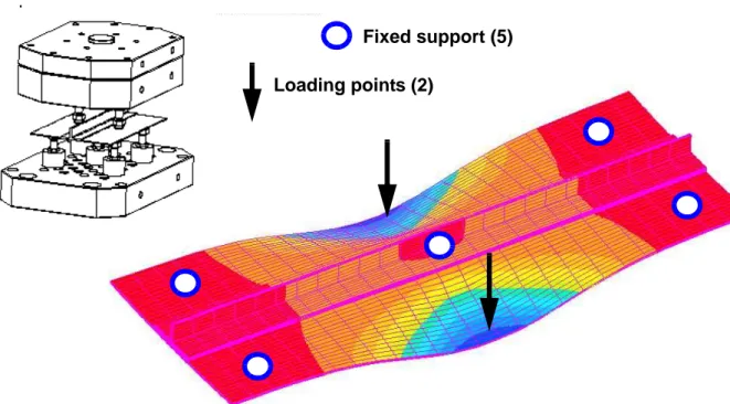
The principle of 7-point bending tests is given in Figure N° 2. Five points serve as sup-ports for the skin part of the test piece. The supsup-ports used are adjustable and enable hyper-statism and flatness defects of the specimens to be managed. Moreover, each support includes a load sensor. The upper block is mobile and composed of two supports. A displacement sensor (LVDT) is installed on the mobile block so that its displacement can be known accurately. The supports in contact with the specimens are articulated to limit their punching effect during test-ing. A pre-sizing calculation was performed to position the supports in such a way as to avoid any fracture before debonding.
It is possible to simulate different fields of displacement by modifying the position of the movable points. The term chosen for this is symmetrical bending (Figure 3) for the type of buckles obtained in compression and antisymmetrical bending for the type obtained in shear (Figure 4). As the assembly is hyperstatic, the supports can be adjusted manually and
incorpo-rate force sensors. It is thus theoretically possible to compensate for flatness defects in the specimens. Half of the 10 specimens were used for symmetrical bending tests and the other half for antisymmetrical bending tests.
2.2 - Test results and analysis.
The forces measured by the 7 sensors in the case of symmetrical tests are shown in Figure 5. Globally, the test seems fairly reproducible. The lower middle support (support 3) took up most of the force imposed by the upper supports. The scatter over 5 tests was limited to 14 %. The behaviour and scatter were of the same type for the antisymmetrical tests, with a different distribution of forces on the supports. Debonding was detected at the first discontinuity of the force vs displacement curves. It occurred at the skin/stringer interface or at the interface of the ply immediately above (90°/45° interface) and propagated abruptly. The aspect of the deb-onded specimens is shown in Figure 6 and the morphology obtained by C-Scan is also given in the same figure.
The tests were reproducible but, although the scatter remained limited for the symmetrical tests (14%), it reached 32% for the antisymmetrical tests. Analysis showed that the lowest val-ues and highest valval-ues were obtained for the same specimen batches, which appears to indicate that the source of scatter was not test related but should be found in the differences in the fabri-cation of the specimens.
2.3 - Reference model and test correlation.
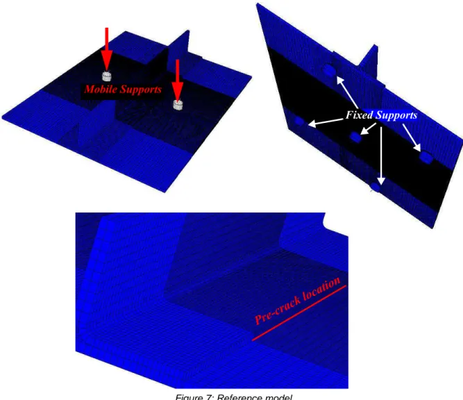
A first reference model based on 3D shells was created using the Abaqus software (Fig-ure 7). The supports were modelled as rigid bodies in contact with the skin. Each support was free in rotation and loading was obtained by the displacement of the upper supports. The lower supports were blocked in translation along the three directions. The symmetrical and antisym-metrical tests were simulated by simple repositioning of the supports and change of the contact
zones. The elements between the stringer and the skin were coincident at the edge of the flange and refined in the zone where the debonding criterion applied. The VCCT technique was used and the Benzeggagh-Kenane criterion [21] was applied to one side only of the stringer so as to represent the lack of symmetry obtained during testing. The pre-crack was 0.5 mm long.
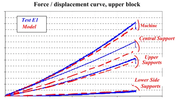
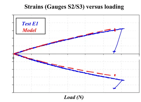
The response of the specimen in terms of machine force/displacement (Figure 8) shows that the simulated behaviour was globally in agreement with the experimental behaviour. The measurements showed that the central support took most of the force and the lateral supports became load-bearing beyond 1 mm. The simulation underestimated the force on the central support by about 15% at debonding. Analysis of the strains in the flange (S2, Figure 1) and under the skin (S3, Figure 1) indicated that the level of bending found experimentally was close to the simulated level (Figure N° 9). The same overall behaviour was obtained for the antisymmetrical case [3]. The computed locations for the onset of debonding (Figure 10) agreed with those found experimentally (see Figure 6).
For the symmetrical case, the computed debonding load was within 7 % of the first frac-ture load observed in test E1 and within16 % of the mean fracfrac-ture load. Considering the high scatter in the test results (about 14 %), this value is perfectly acceptable. For the antisymmetri-cal case, the computed debonding load was within less than 1% of the minimum debonding load obtained experimentally and within 19 % of the mean of the tests. Considering the high scatter in the test results (32%), this result is acceptable. The modal distribution at the failure load was of the same type for both tests. Mode I was preponderant and the ratio of GII/ (GI+GII) was 33% for the symmetrical test and 29% for the antisymmetrical test.
To sum up, the reference model enables the experimental behaviour of the specimens in 7-point bending tests to be correctly apprehended. The combined use of the Benzeggagh-Kenane criterion and the VCCT method again shows its efficiency with respect to a more com-plex problem. However, the main problem for this kind of modelling lies in the computing
time, which is of the order of half a day because due to the mesh refinement needed for conver-gence. Using a global/local approach should lead to a distinct improvement in the time. It is the subject of the next section.
2.4 - Global/local approach.
The interest of this method lies in the fact that it dissociates the non-linear model required for the postbuckling computation from the model required for the debonding computation. Local models that are refined but of small size can be used for detailed studies of specific zones and a model can be used as often as necessary at different places on the panel. The prin-ciple is based on the use of fields of displacement of a zone likely to undergo debonding, pro-vided by the global model, by reinjecting these displacements at the boundaries of a local model better suited to the debonding analysis. As communication between the two scales only goes in one direction, any change in stiffness due to debonding in the local models will not be taken into account in the global model. In consequence, only the onset of debonding can be analyzed by this method. Nevertheless, this approach is consistent with the sizing principle for composite aeronautical structures, which does not tolerate any crack propagation. Moreover, tests at structure level show that failure is generally explosive, suggesting that the debonding phenomenon is unstable and that seizing the onset of debonding should suffice to compute the failure of the structure.
Two models were used in accordance with the process described above. The global model is presented in Figure 11. The skin, the flange and the web of the stiffener were modelled using reduced-integration linear plate elements (S4R). The link between the flange and the web of the stiffener was described by rigid links, as was the link between the web of the stiffener and the flange. So the radii between the web and the flange were not modelled. In accordance with the reference model used previously, loading was applied using seven supports, two of which
(upper supports) were subjected to imposed displacements to produce the required loading. The global computation was non-linear geometric.
The local model comprised a skin part and a flange part. The skin and flange were mod-elled by 3D shells of coincident meshes. The displacements coming from the global model were imposed at the boundaries of the local model. The principle of reinjection is given in Fig-ure 12. The boundary nodes of the global model were recreated in the local model at their geo-metric locations (master nodes). The nodes of the 3D shell elements of a section of the local model (slave nodes) were controlled geometrically by the 5 d.o.f. coming from the nodes of the plate elements following the Kirchhoff-Love hypothesis and via rigid elements. The choice of the size of the local model is studied in [3] on a virtual test patch. The optimum size needed to verify the St Venant assumption is about half a wavelength. Therefore, the problem is more defined by the time needed to build the local model than by the minimum size. If the analysis area is too small, too many local models are needed. The "virtual crack" is 0.5 mm long. The VCCT technique is used to determine the energy release rates and the Benzeggagh-Kenane cri-terion is applied. The local calculation is non-linear requiring two or three steps.
The global/local comparison for one increment of displacement is given in Table 1. The deflections obtained in the two cases were comparable and the difference was less than 3%, showing that the bends were practically identical. The local stress state could thus be correctly obtained directly and the energy release rates in mode 1 were identical to within 3%. The dif-ference was greater in mode 2 and reached 15 % for the symmetrical case. The Benzeggagh-Kenane criterion was little affected, however, and the difference for both cases was less than 3.5%, which validated the global/local approach. The only notable difference between the two models came from the force exerted on the assembly to obtain the correct deflection (differ-ence 12.5 % and 9%). This differ(differ-ence can be attributed to the rigidity of the links used between the skin and the stringer, which did not allow the displacements to be continuously represented
and altered the global stiffness. To sum up, the global/local method has been validated by anal-ysis of the 7-point bending tests and it is possible to move on to larger sized problems. Moreo-ver, the objective of reducing computing time was achieved, i.e, a complete computation loop with the global/local approach takes about twenty minutes.
3 - PANEL ANALYSIS
3.1 - Introduction
The two tests presented in this part are not specific to this study but form part of the cer-tification process for a current Airbus programme. Therefore, only the general methodology of the tests and numerical approach are given here. The aim is to validate the approach for a higher level and in an operational context. The problem of correlating with structural tests at these scales will not be presented here since it is long and complex and involves certain data that cannot be disclosed but the essential points can be found in [3]. The present paper will limit itself to applying the global/local approach and the Benzeggah-Kenane criterion general-ized to mode III for these tests on panels. It appears that the dominant debonding mode at these scales is mode III and the criterion is modified as follows, assuming by default that :
(eq 1) Two uniaxial tests were analyzed: one under compression and one under shear.
3.2 - Tests description and failure analysis.
The two stiffened panels used in the programme were composed of a panel and three omega stringers made of carbon/epoxy laminate. No adhesive film was used for the fabrication and the stiffened panels were co-cured. The geometry of the panel under compression is given in Figure 13 (a). Two 50 mm resin blocks were molded at the ends of the panel so that the com-G2C = G3C GC G1 C G2 C G1 C – ( ) G2+G3 G1+G2 +G3 --- η ⋅ + =
pressive load could be applied through the test equipment. The edges of the panel were stabi-lized by guides. The shear test was carried out using a deformable square [8]. The panel under shear also had three stringers. The edges of the panel were reinforced by carbon/epoxy and glass/epoxy to avoid local failure of the panel near the loads introduction and to ensure the most uniform possible load transfer. Three lines of bolts were used. The first line was com-posed of titanium fasteners whereas the last two lines were comcom-posed of steel fasteners. This choice gave a better spread of the load among the fasteners.
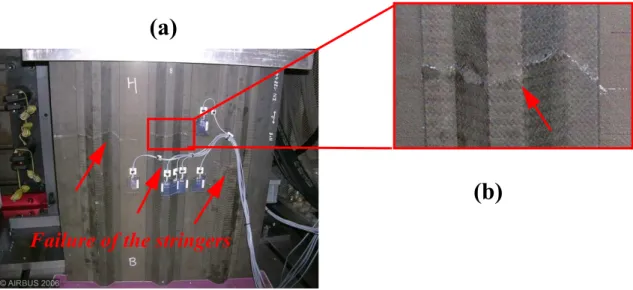
For the compression test, the three stiffeners were cracked through but the breaks were not situated in the same plane (Figure 14). The skin was practically undamaged apart from local damage at one of the guides (possibility of secondary break). This implies that the overall buckling was not the source of the failure. Analysis of the stingers showed no visible debond-ing, which means that fracture was due to excessive stress in the stiffeners. Buckling was detected by a loss of linearity of the gauges at 24.3 kN and the breaking load was 106 kN. Shearing failure was explosive and was caused by the debonding of the central stiffener (Fig-ure 15). Buckling was detected by the loss of linearity of the gauges and by image correlation at 360 kN . The breaking load was 425 kN.
3.3 - Global/local finite element analysis of skin/stiffener debonding.
The global model for compression can be seen in Figure 16. The Abaqus software was used and plate elements (S4R) were chosen to model the structure as a whole. The resin blocks on either side of the panel were considered to impose the clamping conditions modelled by the rigid links between the (master) "steering" nodes and the (slave) nodes at the ends of the panel. The anti-buckling guides were modelled by simple support conditions over the whole surface of contact. The internal radii of the stiffeners were not modelled but this hardly changed the overall stiffness of the panel. The interfaces between the skin and the flanges of the stringers
were modelled by rigid links ensuring load transfer only.
The shear global model is shown in Figure 17. The composite panel was modelled in the same way but, to properly represent the postbuckling behaviour, it was necessary to represent the reinforcing plies, the frame itself (in volume elements) and the various attachment points. Rotation of the different parts of the frame was allowed by controlling the local contacts. Force transfers between the frame and the stiffened panel were ensured by connectors (elements defined by 6 rigidities in translation and rotation). The shearing rigidities of the connectors representing the fasteners were given by Huth's model [24]. The model has 7 million degrees of freedom. The two models gave acceptable correlation with the tests and the details in terms of loads/displacements and local strains given by the gauges can be found in [3].
The global/local approach presented and validated by the 7-point bending test was applied to both cases (Figure 18). The main modification was that the omega shape of the stringers made necessary the study of the debonding on both sides of the flange. To respect the St Venant hypothesis and thus avoid the boundary conditions at the edges of the local model perturbing the results, pieces of skin and stiffener web were modelled. The nodes in the thick-ness were steered in the same way as for the 7-point bending test, on the basis of the Kichhoff-Love hypothesis (Figure 12). The size of the local model was about a quarter of the length of the panel, which allowed the structure to be covered with a good compromise between com-puting time and accuracy [3]. The local model was built up of 3D shells and the radius between the flange and the web of the stringer was modelled. The resin corners could vary from one stringer to another. It was therefore decided not to model them and to place the virtual crack at the flange/web radius (Figure 18). This hypothesis is very conservative, as shown in [15].
In compression, the model predicted initial buckling of the panel at 20300 N while experiment recorded 24600 N, i.e. a difference of about 15 %. Although this discrepancy seems large, the theory of buckling shows that a variation of 56 hundredths of a millimetre in
the thickness (ply thickness of 0.132 mm instead of 0.125 mm) would be enough to explain the difference considering the thickness of the panel. This hypothesis seems realistic as, in other tests carried out at Airbus where the actual thickness was measured, the true thickness of a ply was 0.13 mm.
Numerically, the behaviour of the panel in compression shows three distinct phases. After the simple compression phase, a symetric buckling of the skin produces 11 waves. The amplitude of the buckles gradually increases up to about 108000 N where a change of mode occurs, introducing two additional waves. Similarly, the height of the buckles continues to increase until general buckling of the stiffened panel occurs at 153 800 N. The Tsai-Hill crite-rion is reached at the hat of the stiffener and at the failure locations identified in testing (Figure 19) for a load of 106 085N, i.e. within 1% of the measured failure load. The generalized Ben-zeggagh-Kenane criterion is reached at 144 900 N, which is well above the observed and com-puted failure load. The aspect of the debonded area in the local model is shown in Figure 19. If debonding had taken place, it would have occurred at the level of the free edges of the flange. The calculations show that, once the debonding load is reached, the propagation of debonding is unstable. Debonding would thus lead to explosive failure. For the compression test, the numerical model is in agreement with the tests even if debonding of the stringer is not the source of the postbuckling failure of the stiffened panel.
For the shear case, the same numerical methodology was used. The calculated buckling load was 338 kN, as compared with the 360kN obtained experimentally. The error on the buck-ling load is thus about 10 %, which is acceptable considering the complexity of the test. After scanning the structure, the critical site was indeed found in the centre of the panel at the free edge of the flange of the central stringer, at the level of the largest buckle. Debonding was reached at the critical site for 469 KN, the error being 9.4 % with respect to the test result (425 KN). This error, which is reasonable considering the complexity of the test, could be due to
two phenomena:
•the non-linear behaviour of the panel is not perfectly represented in spite of the very fine modelling used,
•the value of the energy release in mode III is not identical to that of mode II although it is usual to make the approximation
The most probable hypothesis is that both these aspects play a part in the forecasting error. Mode III has not been very well analyzed and the errors concerning the prediction of the field of displacements of the panel may lead to an overestimate of the debonding load.
The debonding modes at the critical sites are given in Figure 21. It is clear that mode 3 is dominant at failure for both loading cases. It is worth recalling that, despite the apparent simi-larity in terms of bending, mode 1 was dominant in the debonding zone for the 7-point bending test. While the study by Falzon and Steven [25] shows that debonding tends to take place in the "belly" of the buckles where opening is maximum and mode III is negligible, the present study shows that this is not necessarily the case for panels stiffened with omega stringers, which themselves have thin flanges. Moreover, this presence of mode III brings out the need to develop standardized, reliable characterization methods in order to be able to study the often neglected effects of this mode in greater detail. This analysis also shows that debonding fol-lows a quasi-exponential increase in the energy release rates at the stringer/skin interfaces. It is therefore possible to use strongly reduced values for the calculations without engendering seri-ous conservativeness on the postbuckling margin [3]. A preliminary calculation assuming that mode 1 is lowered by 30% and modes II and III by 50% shows that the debonding criterion is satisfied at 411 kN for the shear case, i.e. at a loading only 12.4 % lower than the calculation performed with the mean values of the critical energy release rates. For the compression case, the debonding load is found at 133 kN, a reduction of only 8.2 %. It is thus possible to use strongly reduced values when making the calculations without causing undue conservativeness
G2 C
G3 C
on the postbuckling margin. This point should enable the number of tests required to character-ize the interfaces to be made considerably smaller and allow conservative pre-sizing in the early stages of a programme.
4 - GENERAL CONCLUSION
The multiscale analysis of stiffener debonding proposed in the first part has been applied at the "element" and "panel" levels. At element scale, the study concerned the debonding of stringers in 7-point bending. From a numerical point of view, a global/local approach was applied and enabled calculation of the loads corresponding to local debonding. At this stage, the mixed Benzeggagh-Kenane criterion was validated together with the computing method. Moreover, in a certification programme, the methodology was applied to stiffened panels under compression and shear. The prediction of debonding at this scale is consistent with the tests. The dominant debonding mode for the technology studied is mode III. This observation should encourage more fundamental studies of this mode in composites as the available data are very patchy. To sum up, a multi-level experimental and simulation approach has been vali-dated for static loads. If the mass of composite structures is to be optimized, it would be desir-able to lower the threshold for postbuckling below the limit loads. However, it would then become necessary to use the same multi-level approach for fatigue. From a modelling stand-point, the non-linear analysis of strengthened panels in postbuckling proves extremely costly in terms of computing time and, if a full fuselage is to be treated, it will be beneficial to develop intensive computing methods.
5 - REFERENCES
[1]Krueger R., Cvitkovitch M. K., O’Brien T. K., Minguet P.J.: Testing and analysis of composite skin/ stringer debonding under multi-axial loading. Journal of Composite Materials 34 (2000) : 1263-1300. [2]Meeksa C., Greenhalghb E.,Falzonc B. G.: Stiffener debonding mechanisms in post-buckled CFRP aerospace panels. Composites: Part A 36 (2005) 934–946
[3]Bertolini J. Contribution à l’analyse expérimentale et thèorique des ruptures de structures compos-ites en postflambement par décollement de raidisseurs. Thesis Université Paul Sabatier, Toulouse, April 2008 (in french) http://thesesups.ups-tlse.fr/
[4]Zimmermann R., Klein H., Kling A.: Buckling and postbuckling of stringer stiffened fibre compos-ite curved panels – Tests and computations Composcompos-ite Structures 73 (2006) 150–161
[5]Degenhardt R., Rolfes R., Zimmermann R., Rohwer K.: COCOMAT—improved material exploita-tion of composite airframe structures by accurate simulaexploita-tion of postbuckling and collapse. Composite Structures 73 (2006) 175–178.
[6]Degenhardt R., Kling A., Rohwer K., Orifici A.C., Thomson R.S.: Design and analysis of stiffened composite panels including posbuckling and collapse. Computers and Structures 86 (2008) 919-929. [7]Orifici A.C., Thomson R.S., Degenhardt R., Kling A., Rohwer K., Bayandor J.: Degradation investi-gation in a postbuckling composite stiffened fuselage panel. Composite Structures 82 (2008) 217–224. [8]Farlay G. L., Baker D.J. : In plane shear test of thin panels. Experimental mechanics (1983) pp 81-88.
[9]Ambur D. R., Jaunky N. Hillburger M. W. : Progressive failure studies of stiffened panels subjected to shear loading. Composite Structure 65 (2004) 129-142.
[10]Sheppard A.T., Leong K.H., Kelly D.W., Raju J.: Rib separation in postbuckling stiffened shear panels. Composite structures 43 (1998) 339-352.
[11]Romeo G., Frulla G. (1992): Buckling and postbuckling behavior of anisotropic plates under com-bined biaxial compression and shear loads. ECCM Composite Testing and Standardization (Amsterdam 09/92).
[12]Marshall Rouse; Richard D. Young; Ralph E. Gehrki, Structural Stability of a Stiffened Aluminum Fuselage Panel Subjected to Combined Mechanical and Internal Pressure Loads, AIAA 2003-1423; 44th AIAA/ASME/ASCE/AHS/ASC Structures, Structural Dynamics, and Materials Conference, Nor-folk, Virginia, April 7-10, 2003
[13]Castanié B, Barrau J.J., Jaouen J.P., Rivallant S.: Combined shear/compression structural testing of asymmetric sandwich structures, Experimental mechanics, Vol 44 (5), pp 461-472, Octobre 2004. [14]Li J., Dávila C. G., Chen T-K.: High Fidelity Failure Analysis for a Composite Fuselage Section, American Helicopter Society 57th Annual Forum, Washington, DC, May 9-11, 2001.
[15]Bertolini J., Castanié B., Barrau J.J., Navarro J.P. : An experimental and numerical study on omega stringer debonding. Composite Structure 86 (2008) 233-242.
[16]Van Rijn J, Wiggenraad J. A seven-point bending test to determine the strength of the skin-stringer interface in composite aircraft panels. Amsterdam, Netherlands: National Aerospace Lab; 2000.
NLR-TP-2000-044.
[17]Krueger R.: Virtual crack closure technique: History, approach, and applications Applied Mechan-ics Reviews 2004 Vol 57, Issue 2, pp. 109-143.
[18]Krueger R., Minguet P.J.: Analysis of composite skin–stiffener debond specimens using a shell/3D modeling technique. Composite Structures, Volume 81, Issue 1, November 2007, Pages 41-59.
[19]Camanho P. P., Davila C. G., De Moura M. F.: Numerical Simulation of Mixed-Mode Progressive Delamination in Composite. Journal of Composite Materials 2003; 37; 1415-1438.
[20]Turon A., Camanho P.P., Costa J., Davila C.G.: A damage model for the simulation of delamination in advanced composites under variable-mode loading. Mechanics of Materials 38 (2006) 1072–1089. [21]Benzeggah M.L., Kenane M.: Measurement of mixed-mode delamination fracture toughness of unidirectional glass/epoxy composites with mixed-mode bending apparatus. Composite science and technology 56 (1996) 439-449.
[22]Cosentino E., Weaver P.M.: Approximate Nonlinear Analysis Method for Debonding of Skin/ Stringer Composite Assemblies. AIAA Journal 46 (2008) 1144-1159.
[23]A.C. Orifici, R.S. Thomson, I. Herszberg, T. Weller, R. Degenhardt, J. Bayandor: An analysis methodology for failure in postbuckling skin-stiffener interfaces. Composite Structures (2008) 186-193 [24]H. Huth, Influence of the fastener flexibility on the prediction of load transfer and fatigue life for multi-row joints. In: J. Potter, Editor, Fatigue in mechanically fastened composite and metallic joints. ASTM STP927, ASTM, Philadelphia (1986), pp. 221–250.
[25]Falzon BG, Steven GP : Buckling mode transition in hat-stiffened composite panels loaded in uniaxial compression, Composite structures 37 (1997) pp 253 - 267.
FIGURES
Figure 1: Specimen overall geometry and location of the strain gauges.
100,00 200,00 3 0 0 ,0 0 2 .1 6 4.32 50,00 R 2 Resine 2 5 ,0 0 0° 17 1 7 ,0 0 30,00 S1 S 2 S 3 S4 S5 S 6 S 7 S8 S1 S 2 S 3 S 4 S 5 S6 S7 S8 1 5 0 ,0 0 S10 S9 S9 S10 3 0 0 ,0 0
(a)
.
Figure 2: Principle of 7-point bending test (symmetrical case).
Fixed support (5) Loading points (2)
Figure 3: Symmetrical 7-point bending tests.
Figure 4: Antisymmetrical 7-point bending tests. Support Points
Loading Points
Figure 5: Force/displacement curves for symmetrical test cases.
Figure 6: Debonded patterns (a) : symmetric case, (b) : antisymmetric case.
Courbe effort / déplacement bloc supérieur
0 500 1000 1500 2000 2500 3000 3500 4000 0 0,5 1 1,5 2 2,5 3 3,5
Déplacement machine (en mm)
E ff o rt ( e n N ) 4 5 3 6 7 1 2 Machine Appuis 1 et 2 Appui 3 Appuis 4, 5, 6 et 7
Force / displacement curve, upper block
Machine displacement (mm) F o rc e (N ) Support 3 Support 1 and 2 Support 4,5,6 and 7 Debonded area Debonded area
Figure 7: Reference model. Appuis mobiles Appuis mobiles Appuis fixes Pre-c rack l ocatio n Mobile Supports Fixed Supports
Figure 8: Test/simulation correlation (symmetrical case): curve of force/displacement at supports.
Courbe effort / déplacement bloc supérieur
0 500 1000 1500 2000 2500 3000 3500 0 0,5 1 1,5 2 2,5 3 3, 5
Déplacement machine (en mm)
E ff o rt ( e n N ) ESSAI E1 MEF Machine Appui central Appuis supérieurs Appuis inférieurs latéraux
Force / displacement curve, upper block
Machine displacement (mm) F o rc e (N ) Central Support Upper Supports Lower Side Supports Test E1 Model
Figure 9: Test/simulation correlation (symmetrical case): curve of force/displacement at supports.
Figure 10: Debonding location and computed pattern. D é f o r m a t io n s S 2 /S 3 / E f f o rt m a c h ine -5 00 0 -4 00 0 -3 00 0 -2 00 0 -1 00 0 0 1 00 0 2 00 0 3 00 0 4 00 0 5 00 0 0 5 00 10 0 0 1 5 00 2 00 0 25 0 0 30 00 3 50 0 E ff o r t m a c h in e ( e n N ) D é fo rm a ti o n ( e n µ d e f) ESSAI E2 MEF S tr a in s (µ st ra in s)
Strains (Gauges S2/S3) versus loading
Load (N)
Test E1 Model
Figure 11: Global/local approach
Figure 12: Principle of global/local boundary element displacement injection.
Shell elements Solid elements Drivi ng no des Pre-c rack Skin Flange g
Figure 13: Compression (a) and shear test principle (b). Pains de résine (50 mm chacun) C h a rg e Y X 191.6 mm 191.6 mm C h a rg e Guides anti-flambement (690 x 30)
(a)
(b)
Guides Lo a d Lo a dFigure 14: Failure mode in compression (a): global; (b): view of the stringer.
Figure 15: Failure mode in shear.
(a)
(b)
Failure of the stringers
Figure 16: Global model for the compression case.
Figure 17: Global model for the shear case.
Simply-supported
F
F
Clamped
Figure 18: Global/local analysis.
Master nodes Inner radius pre-crack
Figure 19: Finite element result of the compression case.
Figure 20: Finite element result of the shear case.
Static failure at 106 100 N
(Tsai-Hill Criterion)
Local debonding of
the central stringer
at 144 900 N
Figure 21: Modal evolution at the critical site in compression (a), shear (b).
E v o lu tio n s m o d a le s (s ite c r itiq u e )
0 2 0 0 4 0 0 6 0 0 8 0 0 1 0 0 0 1 2 0 0 1 4 0 0 0 5 0 1 0 0 1 5 0 2 0 0 2 5 0 3 0 0 3 5 0 4 0 0 4 5 0 5 0 0 C h a r g e (K N ) G ( J /m ²) G I G II G III E v o lu tio n s m o d a le s 0 2 0 0 4 0 0 6 0 0 8 0 0 1 0 0 0 1 2 0 0 1 4 0 0 0 2 5 0 0 0 5 0 0 0 0 7 5 0 0 0 1 0 0 0 0 0 1 2 5 0 0 0 1 5 0 0 0 0 C h a rg e (N ) G ( J /m ²) G I G II G III
Load
Modal evolutions
Modal evolutions (critical site)
(a)
TABLES
Table 1: Reference and global/local model comparison.
Reference model Global/local model Reference model Global/local model Loading point displacement (Normalized) 0,56 0,56 1 1 Load (Normalized) 753 860 1000 1098 Maximum deflection (Normalized) 0,8 0,78 1,64 1,61 G1 (J/m 2 ) 223 216 272 264 G2 (J/m 2 ) 109 92 123 114 B-K Criterion 0,69 0,67 0,87 0,84 Antisymmetric case Symmetric case