HAL Id: hal-01781513
https://hal-mines-albi.archives-ouvertes.fr/hal-01781513
Submitted on 20 Oct 2018
HAL is a multi-disciplinary open access
archive for the deposit and dissemination of
sci-entific research documents, whether they are
pub-lished or not. The documents may come from
teaching and research institutions in France or
abroad, or from public or private research centers.
L’archive ouverte pluridisciplinaire HAL, est
destinée au dépôt et à la diffusion de documents
scientifiques de niveau recherche, publiés ou non,
émanant des établissements d’enseignement et de
recherche français ou étrangers, des laboratoires
publics ou privés.
Upgrading greenhouse gases (methane and carbon
dioxide) into syngas using nickel-based catalysts
Bruna Rêgo de Vasconcelos, Doan Pham Minh, Nathalie Lyczko, Thanh Son
Phan, Patrick Sharrock, Ange Nzihou
To cite this version:
Bruna Rêgo de Vasconcelos, Doan Pham Minh, Nathalie Lyczko, Thanh Son Phan, Patrick Sharrock,
et al.. Upgrading greenhouse gases (methane and carbon dioxide) into syngas using nickel-based
catalysts. Fuel, Elsevier, 2018, 226, p.195-203. �10.1016/j.fuel.2018.04.017�. �hal-01781513�
Upgrading greenhouse gases (methane and carbon dioxide) into syngas
using nickel-based catalysts
Bruna Rego de Vasconcelos
⁎, Doan Pham Minh, Nathalie Lyczko, Thanh Son Phan,
Patrick Sharrock, Ange Nzihou
Université de Toulouse, Mines Albi, UMR CNRS 5302, Centre RAPSODEE, Campus Jarlard, F-81013 Albi cedex 09, France
G R A P H I C A L A B S T R A C T Keywords: Greenhouse gases Catalyst deactivation Basicity Solid solution Carbon gasification A B S T R A C T
In this work, Mg-doped Al2O3supports were used for the preparation of Ni catalysts, which were then tested in
dry reforming of methane reaction (DRM) for syngas production. The influence of MgO content (0–70 wt%) on the basicity of the catalysts as well as on the formation of a NiO-MgO solid solution was investigated and linked to the catalytic performance of the catalysts. The catalyst containing high amount of Mg (Ni/70MgAl) showed the best performance with negligible deactivation rate over 50 h of time on stream (TOS). The presence of strong basic sites in this catalyst was important to adsorb carbon dioxide (CO2), to gasify the coke deposit and to
increase the syngas production. Also, the presence of a NiO-MgO solid solution led to strong metal-support interaction, which limited the sintering of nickel particles. The quantification of the water formed during the reaction showed that its formation was crucial for the elimination of the coke deposits as well as to increase the syngas production.
1. Introduction
CO2 reforming of methane, also known as dry reforming of
me-thane, (Eq.(1)) has received great attention in the past few years since it converts CO2and CH4, the two main greenhouse gases, into syngas,
which can be later used for the production of energy, fuels and
added-value chemicals, such as dimethyl ether, formaldehyde, olefins, etc
[1,2].
Dry reforming of methane (DRM): + ↔ +
° = ° = −
H G
CH CO 2H 2CO
∆ 4298 247 kJ/mol; ∆2 2 61770 67.32 T (1)
⁎Corresponding author at: Ecole des Mines d’Albi-Carmaux, 81000 Albi, France.
E-mail address:bregodev@mines-albi.fr(B. Rego de Vasconcelos).
Despite the economic and environmental benefits of this process, there is not yet a DRM full scale plant operation up to date[3]. The main reasons are the high energy requirements of the reaction and the fast deactivation of the catalysts due to coke deposition and sintering of both support and active phase at high reaction temperatures.
So, much effort has been done to develop thermally stable catalysts with good performance for this process. Supported noble metal (Ru, Pd, Pt and Rh) catalysts proved to have good catalytically performance. However, their high cost and limited availability are significant draw-backs [4–6]. So, transition metals, especially Ni, have been widely studied due to their lower cost and higher accessibility compared to noble metals and proven activity in this process[7]. Nevertheless, they were reported to be more prone to carbon deposition on the catalyst surface (Eqs.(2) and (3)) and present low resistance against the sin-tering of the active phase, which considerably reduce their stability
[1,8–10]. Boudouard reaction: ↔ + ° = − ° = − + H G 2CO C CO ∆ 298 (s)172 kJ/mol; ∆2 39810 40.87 T (2) Methane cracking reaction:
↔ +
° = ° = −
H G
CH C 2H
∆ 4298 (s)75 kJ/mol; ∆2 2190 26.75 T (3) So, there has been many studies to improve the coke resistance of the Ni-based catalysts. One possible pathway is the addition of alkali promoters, which increase the basicity of the support and favors the CO2adsorption which will further oxidize the carbon deposit[11–15].
According to Ballarini et al.[14], these promoters may act as texture, structure and activity promoters, enhancing the thermal stability of the alumina-based supports and preventing sintering of the support and of the active phase. They would also improve the metal dispersion and the ability of the catalyst to gasify the coke deposit. San Jose-Alonso et al.
[16]investigated the influence of potassium (K) over the performance of the Co/Al2O3 catalyst. Promoted catalyst showed lower coke
de-position compared to unpromoted catalyst. This was explained by a partial coverage of the active sites for the methane decomposition by K addition and its ability to catalyze the carbon gasification reaction.
Several works have demonstrated that the formation of a NiO-MgO solid solution could also hinder the deactivation by coke deposition. Bradford and Vannice[11]showed that the formation of NiO-MgO solid solution could stabilize the Ni particles, which prevented carbon de-position over Ni/MgO catalyst in DRM reaction. Hou et al.[17]added that the combination between NiO and MgO results in a very stable solid solution with a basic character, which is efficient in inhibiting the coke deposit.
Addition of water to the feed has also been used to inhibit carbon formation via a carbon gasification reaction (Eq.(4))[11].
Carbon gasification:
+ ↔ + H° =
C(s) H O H2 2 CO ∆ 298 131 kJ/mol (4) Rostrup-Nielsen [18] showed that the coke could be gasified by different gases such as hydrogen, carbon dioxide and steam. However, steam would be the most effective one. Similar conclusions were ob-tained by Figueiredo et al.[19]. They showed that the rate of coke gasification with hydrogen is considerably slower than with steam.
In the present work, Ni supported on Mg-doped Al2O3 catalysts,
with different amounts of MgO, were tested in the DRM reaction. The aim was to understand the influence of the catalysts basicity (linked to the amount of Mg) on the catalyst activity and stability, and the role of the water formed during the reaction. The novelty of this work is the successful combination of different methods for structural character-ization of catalysts before and after catalytic test to understand the deactivation mechanism and the impact on the conversion of CO2and
CH4into syngas. The water formed during the reaction could be
ex-perimentally quantified and linked to the catalytic performance of catalysts synthesized in this work. This contributes to the basic un-derstanding of DRM process and to the design of an efficient catalyst for DRM.
Fig. 1. XRD patterns of the fresh catalysts.
Table 1
XRD characterization of the 70MgAl support and Ni/70MgAl catalyst.
Sample MgO or solid solution XRD
parameters Possiblematch (wt%)MgO RBragg *** 2θ Cell a = b = c (Å) d* (nm) 70MgAl 42.88 4.214 12.8 MgO 59.7 1.81
Ni/70MgAl 42.86 4.212 16.9 MgO or solid solution
66.2** 1.88
* Crystallite size calculated using the Scherrer equation. ** Considering that the peak at 42.86° correspond only to MgO. *** From Rietveld refinement.
Fig. 2. TEM of fresh catalysts: (a) Ni/Al, (b) Ni/30MgAl and (c) Ni/70MgAl; pink arrow: nickel particle. (For interpretation of the references to colour in this figure legend, the reader is referred to the web version of this article.)
Fig. 3. EDX mapping of Ni/Al catalyst.
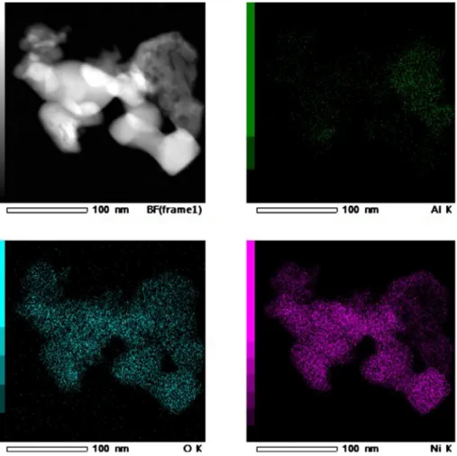
Fig. 4. EDX mapping of Ni/30MgAl catalyst.
2. Materials and methods 2.1. Catalyst preparation
Commercialγ-Al2O3and hydrotalcite-based supports (PURAL® MG)
provided by Sasol (Germany) were employed as catalysts supports. In this work, two hydrotalcite-based supports with different MgO/Al2O3
weight ratios were used: PURAL MG30 (30:70) and PURAL MG70 (70:30). The three supports (Al2O3, PuralMG30 and PuralMG70) were
first sintered at 1200 °C for 5 h in order to stabilize them and avoid later catalyst deactivation by support sintering. Then, the catalysts were prepared by impregnating the sintered supports with an aqueous so-lution of Ni(NO3)2·6H2O (Fisher Scientific) by incipient wetness
im-pregnation method. The loading amount of Ni was 5.7 wt% for each
sample. After the impregnation, the powder was dried at 105 °C. No further calcination was performed prior to the catalytic tests since the temperature employed during the reduction and reaction phases (700 °C) are enough to decompose the water and nitrates from the catalyst and these are the only species decomposed during a calcination of these catalysts (Fig. S1, supplementary material). The catalysts are referred as Ni/Al, Ni/30MgAl and Ni/70MgAl for Al2O3, PuralMG30
and PuralMG70 supports, respectively.
2.2. Catalytic reaction
The dry reforming of methane was carried out in a fixed-bed tubular reactor (8 mm i.d.). 300 mg of catalyst was diluted 2 times with non-porous alumina powder, which was then placed at the center of the reactor, between two layers of the same non-porous alumina. The pressure drop in the reactor was 1.6 bar. The reaction temperature was controlled by a thermocouple inserted into the reactor at the center of the catalytic bed. The catalyst was reduced in situ at 700 °C for 2 h under 4%H2/N2with a flow rate of 70 mL/min. After the reduction step, the
reaction was carried out at 700 °C with a WHSV of 15,882 mL h−1g
cat−1with a synthetic gas mixture containing 20% of
CH4, 20% of CO2and 60% of N2(volume percentage) for 50 h of TOS
(time on stream). A silica gel tube was placed at the outlet of the reactor as water trap for the quantification of water formed during the reaction. Gas products were analyzed by a µ-GC A3000 (Agilent) equipped with a thermal conductivity detector (TCD). A gas counter was also used for the measurement of the total gas flow rate at the reactor outlet. This is mandatory for correctly determining the selectivity and mass balance of the process.
The deactivation rate of the catalysts was calculated as follows: Fig. 5. EDX mapping of Ni/70MgAl catalyst.
4.5 5 5.5 6 6.5 7 0 100 200 300 400 500 600 700
T
C
D
s
ig
n
al
(
u
.a
.)
Temperature (°C)
Ni/Al Ni/30MgAl Ni/70MgAl
=CH X−−CH X × Deactivation rate (%)
conversion after 1 h of TOS conversion after h
1 100
4 4
(5) where: X being equal to 26 or 50 h.
2.3. Catalyst characterization
X-ray diffraction (XRD) patterns of the powdered samples pre-viously calcined at 700 °C under air for 3 h were obtained using a Phillips Panalytical X’Pert MPD diffractometer operating with Cu Kα radiation (λ = 1.543 Å) over a 2θ range of 10–150° and scan step size of 0.042° s−1. Crystallite size was obtained using the Scherrer equation.
N2adsorption isotherms were recorded with a Micromeritics Tristar
II 3020 in order to analyze the specific surface area and the porosity of the fresh catalysts. BET surface area was calculated from the nitrogen adsorption isotherms. Prior to the analyses, the catalysts samples were outgassed at 105 °C for 24 h at low pressure (< 100 mbar).
Basicity of the catalysts previously calcined at 700 °C under air for 3 h was investigated by carbon dioxide temperature-programmed des-orption (CO2-TPD) using a Micromeritics AutoChem 2920 Analyzer
equipped with a thermal conductivity detector (TCD). For each mea-surement, 100 mg of the sample was pretreated at 700 °C (10 °C/min) under helium flow for 1 h. The sample was then reduced under a flow of 25 mL/min of 5%H2/N2for 1 h and then it was cooled to 50 °C at 10 °C/
min under helium flow. The samples were then saturated with 5%CO2/
N2(15 mL/min) for 30 min, before being flushed with helium (25 mL/
min) for 1 h in order to eliminate physisorbed CO2molecules. TPD was
finally performed from 50 to 700 °C at a heating rate of 10 °C/min. Transmission electron microscopy (TEM) images of the fresh cata-lysts calcined at 700 °C under air for 3 h and of the spent catacata-lysts were recorded on a MET JEOL JEM-ARM200F-EDX/EELS. EDX mapping was also performed on the fresh calcined catalysts.
Thermogravimetric analyses (TGA) of spent catalysts were realized in order to qualitatively determine the different types of carbon deposit over the catalysts after the reaction. The analyses were carried out on a SDT Q600 apparatus from TA instruments. 30 mg of the spent catalyst was introduced into an alumina crucible. The sample was then heated under air flow (100 mL/min) up to 1000 °C at a heating rate of 1 °C/ min.
3. Results and discussion
3.1. Textural, structural and chemical features of the fresh catalysts XRD patterns of fresh catalysts calcined at 700 °C under air for 3 h are presented inFig. 1. For the Al support, a phase transition ofγ-Al2O3
toα-Al2O3 was observed as expected. In fact, the α-Al2O3 phase is
usually formed during a high temperature calcination process[14]. The nickel crystallite size on the catalyst Ni/Al was estimated around at 19 nm.
XRD patterns of the 30MgAl support showed the only the presence of the MgAl2O4phase. The Ni/30MgAl catalyst showed the presence of
the MgAl2O4phase and also another phase that could be either NiO or
MgO or, most likely, a NiO-MgO solid solution due to the thermal treatment applied to the catalyst. In fact, it has been extensively re-ported in the literature that NiO and MgO oxides have a NaCl-like lattice structure with very similar lattice parameters. Feng et al.[20]
reported that for MgO, the 2θ values match at 62.6° (2 2 0), 75° (3 1 1) and 79° (2 2 2), while for NiO these values match at 63.2°, 75.8° and 79.81°. Moreover, Ni2+ionic radius is 0.070 nm while the Mg2+radius
is 0.065 nm. These structural similarities explain why NiO and MgO can easily form a solid solution[20–23].
The 70MgAl support presented the MgAl2O4phase, along with MgO
phase, with particle size of 12.8 nm (Table 1). The Ni/70MgAl catalyst still presented MgAl2O4and it also presented another phase that could
be related to MgO or to a NiO-MgO solid solution. To confirm the presence of a NiO-MgO solid solution, the crystallite size and quanti-tative analysis were performed using Rietveld refinement. It is worth noting that MgO crystallite size in the initial 70MgAl support was of 12.8 nm (Table 1). On the other hand, the crystallite size of the possible MgO phase in Ni/70MgAl catalyst was of 16.9 nm. This result suggests the insertion of Ni2+ions into the initial MgO lattice leading to the
formation of a NiO-MgO solid solution. Moreover, the 70MgAl support contained only 59.7 wt% of MgO. It was 66.2 wt% in the Ni/70MgAl catalyst considering that the major peak at 42.86° corresponded only to MgO (Table 1). In addition, no other crystalline phase of nickel oxide was detected in this catalyst. This confirms the formation of the NiO-MgO solid solution. Similar results were obtained by Feng et al.[20]. Rietveld refinement fitted the measured XRD patterns satisfactorily as indicated by the low values of RBraggparameter.
BET surface areas (SBET) and pore volumes (Vp) measurements of the
supports and catalysts revealed negligible SBET and Vp, as expected
since the supports were previously sintered for stabilization.
TEM images of the fresh catalysts are illustrated in Fig. 2. Ni/Al catalyst (Fig. 2a) presented well distinguished Ni-based particles of size around 10–50 nm. The formation of distinguished Ni-based particles (nickel oxide particles, as previously identified by XRD analysis) are confirmed by the EDX mapping presented inFig. 3. Indeed, this figure highlighted the association between Ni and O. However, the Ni is not associated with the Al, highlighting the formation of well-defined nickel oxide particles. Ni-based particles on both Ni/30MgAl (Fig. 2b) and Ni/ 70MgAl catalysts (Fig. 2c) were not well-defined so their size could not
0 10 20 30 40 50 60 70 80 90 100 0 10 20 30 40 50 CH 4 Conv ersion (%) Time on stream (h)
(a)
0 10 20 30 40 50 60 70 80 90 100 0 10 20 30 40 50 CO 2 Conv ersi on (%) Time on stream (h)(b)
Fig. 7. CH4(a) and CO2(b) conversions as a function of TOS for the prepared
catalysts (reaction conditions: 700 °C, 1.6 bar, 15,882 mL h−1g
cat−1): ● Ni/Al;
be estimated. Moreover, the EDX mapping results of these catalysts (Fig. 4andFig. 5, respectively) showed that Ni is always associated to all the other species, highlighting the formation of NiO-MgO solid so-lution as previously identified by the XRD results.
CO2-TPD experiments were conducted in order to evaluate the
amount and the strength of basic sites presented in each catalyst. The objective was to show how the amount of MgO would influence the basicity of the supports and possibly help the coke removal. The amount of the basic sites is represented by the area under the CO2-TPD
curves and the strength of the sites is related to the temperature of CO2
desorption. It has been reported that high desorption temperatures (T > 300 °C) indicate the presence of strong basic sites, while tem-peratures between 200 and 300 °C and lower than 200 °C represent medium and weak basic sites, respectively[24–27].Fig. 6shows the CO2-TPD profiles of the catalysts samples after impregnation and
cal-cination at 700 °C under air. The Ni/Al catalyst showed a small deso-rption peak at around 185 °C, indicating the presence of only small amounts of medium basic sites. This result was not surprising since alumina is known to be an acidic material[24]. The Ni/30MgAl catalyst presented a desorption peak with the maximum at about 250 °C, also
implying the presence of medium basic sites. However, the area under the CO2-TPD curve of this catalyst was larger than the one obtained
with the Ni/Al catalyst, indicating that the total amount of basic sites was larger for the Ni/30MgAl catalyst, as expected due to the presence of Mg. This result is rather interesting confirming that the formation of a NiO-MgO solid solution did not eliminate the basic sites present in-itially on the 30MgAl support due to the presence of MgO. The Ni/ 70MgAl catalyst showed a very broad desorption peak ranging from 100 to almost 500 °C, indicating the presence of weak, medium and strong basic sites. Moreover, this catalyst presented the largest area under the curve, indicating a larger amount of basic sites. The differ-ence between the two Mg-containing catalysts could be related to the initial MgO contents on the supports. Ballarini et al.[14]and Montanari et al.[28]reported that only high amounts of alkali and alkaline earth metals could produce significant amount of different basic sites for alumina-based support, which is the case of the 70MgAl support. Once again, the formation of a NiO-MgO solid solution did not eliminate the basic sites related to the presence of Mg. This is an important parameter since catalysts which are able to strongly adsorb CO2tend to present
high catalytic stability in processes such as DRM. In fact, CO2can gasify
coke deposit preventing the catalyst deactivation[11]. 3.2. DRM test
The catalytic performance of the prepared catalysts during DRM reaction at 700 °C is shown inFig. 7. Also, the selectivity to syngas (desired product) and in water and solid carbon (undesired products) are shown inFig. 8. The real amount of carbon deposited over the catalyst sample could not be measured due to the dilution applied to the
0 10 20 30 40 50 60 70 80 90 100 0 10 20 30 40 50 H2 Selectiv ity (%)
Time on stream (h)
(a)
0 10 20 30 40 50 60 70 80 90 100 0 10 20 30 40 50C
O
S
el
ec
ti
vi
ty
(
%
)
Time on stream (h)
(b)
0 2 4 6 8 10 12 14 16 0 10 20 30 40 50H
2O Selectivity
(%
)
Time on stream (h)
(c)
0 10 20 30 40 50 0 10 20 30 40 50C
(s)Selectivity
(%
)
Time on stream (h)
(d)
Fig. 8. Selectivity in (a–b) desired (H2and CO) and (c–d) undesired (H2O and Cs) products: ● Ni/Al; ■ Ni/30MgAl; ▴ Ni/70MgAl.
Table 2
Deactivation rates of the alumina-based catalysts.
Catalysts Deactivation rate (% h−1)
at TOS = 26 h Deactivation rate (% h−1) at TOS = 50 h Ni/Al 1.09 0.70 Ni/30MgAl 0.54 0.40 Ni/70MgAl 0.01 0.004
catalyst that rendered the sample very heterogeneous. So, the solid carbon selectivity was calculated based on the carbon mass balance.
Ni/70MgAl catalyst showed the best performance under the ex-perimental conditions used. The conversion of methane and carbon dioxide was stable and kept around 80% over 50 h of time on stream (TOS). The selectivity to syngas was also very high (≈80–90%) and was kept constant during the test. In consequence, very low H2O and C(s)
selectivity were observed. The low amounts of water and solid carbon indicate the occurrence of the carbon gasification reaction (Eq.(4)), where the carbon deposit reacts with the water formed to increase the syngas production. Moreover, the presence of strong basic sites in this catalyst favored CO2 adsorption and consequently the solid carbon
gasification (by adsorbed CO2) through Boudouard reaction (Eq.(2)).
This explains the low deactivation rate (only 0.004%/h at 50 h of TOS) of this catalyst (Table 2).
Finally, Ni/Al catalyst, which had negligible support basicity, showed high initial methane and carbon dioxide conversions (≈60%). However, they drastically decreased to ≈20–30% during the first 26 h of TOS before becoming relatively stable. Similarly, the initial syngas selectivity was very high (≈80%) and then it drastically decreased during the first 26 h of TOS. Consequently, high H2O (≈12%) and C(s)
(≈30%) selectivity were observed after 26 h of TOS. This could be explained by the occurrence of side reactions such as reverse water-gas shift (CO2+H CO H O ∆H2 + 2 ° ⇌ =298 41.2 kJ/mol), that consumes H2and CO2to produce H2O and CO and also Boudouard (Eq.(2)) and
methane cracking reactions (Eq.(3)), which are responsible for coke deposition on catalyst surface. This could explain the high deactivation
rate (0.70%/h at 50 h of TOS) of this catalyst (Table 2).
Methane and carbon dioxide conversions were slightly higher with Ni/30MgAl than with Ni/Al catalyst. Ni/30MgAl catalyst still presented considerably high methane and carbon dioxide conversions (≈40–50%) after 50 h of TOS. Syngas selectivity obtained with this catalyst slightly decreased from 78 to 72% for H2, and 84 to 79% for CO
during 50 h of TOS. However, its deactivation rate (0.40%/h at 50 h of TOS) was much smaller (Table 2) compared to pure alumina-based catalyst (0.7%/h at 50 h of TOS). Only trace amount of water was ob-served which suggests that MgO could promote the carbon gasification (Eq.(4)). However, high carbon deposition still took place with the selectivity in solid carbon around 20% after 50 h of TOS.
It is worth noticing that all three catalysts presented high deacti-vation rate during the first 26 h of TOS (Table 2), which indicates that the carbon deposition reactions occurred mainly during this time. Then, the process tended to equilibrium between the carbon deposition and the carbon gasification reactions.
4. Deactivation analysis
The main reasons for the catalyst deactivation are generally coke deposition, which covers the active sites, and the sintering of active phase. In order to better understand the deactivation of the prepared catalysts, TEM and TGA analyses of the spent catalysts were realized.
The morphology of the spent catalysts was observed by TEM with the emphasis on the size of the metal-based particles and on the coke deposit. The TEM images of the three spent catalysts are shown in
Fig. 9.
The screening of different regions of Ni/Al spent catalyst (Fig. 9a and b) revealed the presence of significant amount of carbon deposit under core-shell structure, which covered the nickel-based particles. This type of carbon deposit leads to a complete coverage of the active sites, and consequently to the catalyst deactivation. Wang et al.[29]
reported that the formation of the core-shell/graphite layers structures occurs when the carbon diffusion rate is low, leading to the retention of carbon on the surface of the Ni-based particles. The diffusion of the carbon species through the Ni-based particles also resulted in the for-mation of carbon nanotubes (CNTs) and carbon nanofibers (CNFs). Moreover, the size of Ni-based particles on the spent catalyst was around 50–60 nm while it was around 10–40 nm on the fresh catalyst (Fig. 2a). So the sintering of the active phase occurred during the re-action, which is also known to be responsible for the catalyst deacti-vation.
Spent Ni/30MgAl catalyst (Fig. 9c and d) also showed the presence of core-shell carbon. However, the carbon deposit occurred mostly under CNTs/CNFs form. Sintering of the nickel-based particles was also observed for this sample since the spent catalyst clearly showed nickel-based particles around 10–60 nm while they were not detectable on the fresh sample.
Ni/70MgAl catalyst (Fig. 9e and f) showed rarely core–shell carbon and CNTs/CNFs. Sintering of the nickel-based particles also occurred with the observation of small nickel-based particles (around 10–20 nm) which was not the case for the fresh sample.
The three samples showed the formation of whisker carbon (CNTs and CNFs). In some cases, the CNTs/CNFs embedded the active phase and thus contributed to the deactivation of the catalysts. However, it has been proved in the literature that this type of carbon has little in-fluence on the catalysts deactivation. In fact, they mostly grow away from the catalyst surface and do not cover the active sites. Furthermore, in some cases, the active phase is located at the tip of the carbon structure and thus still accessible to the reactants[29–32].
The comparison between TEM results and the deactivation rate (Table 2) of the catalysts revealed that besides the amount of carbon, the type of carbon deposited on the catalyst and the sintering of the active phase are crucial for the catalyst stability. Ni/Al catalyst, which showed the highest deactivation rate at 50 h of TOS (0.70%/h), strongly Fig. 9. TEM images of spent catalysts after 50 h of TOS: (a) and (b) Ni/Al; (c)
favored the formation of core-shell carbon and the sintering of the nickel-based particles. Conversely, the Ni/70MgAl catalyst, which presented the lowest deactivation rate at 50 h of TOS (0.004%/h), showed the lowest amount of core-shell carbon and the lowest degree of sintering of the active phase.
Thermogravimetric analysis (TGA) of the spent catalysts was per-formed in order to determinate the type of carbon deposited over the catalysts. As different types of carbon decomposes at different tem-peratures, the temperature of the DTG peaks (derivation of TGA curves) were used for the identification of the nature of carbon deposition. For each sample, the analysis was repeated three times and the deviation related to DTG peak position was less than 2%. In some cases, the de-convolution of DTG peaks was necessary in order to properly identify the type of carbon deposit. The deviation of deconvolution was less than 1.5%. The DTG curves of the samples are presented inFig. 10.
Three main DTG peaks could be observed at 280, 450 and 550 °C. Based on TEM results presented above and literature data, these peaks could be assigned to the oxidation of amorphous carbon (Cα), CNTs/
CNFs (Cβ) and core-shell/graphite carbon (Cγ), respectively[32]. These
results slightly differ from results reported in the literature. Wang et al.
[29,33]showed that carbon whiskers (CNTs and CNFs) would be dized around 500 °C and the core-shell/graphite carbon would be oxi-dized only at temperatures above 600 °C. Zhang et al.[34]concluded that the amorphous carbon (Cα), CNTs/CNFs (Cβ) and graphite carbon
(Cγ) would be oxidized in the temperature range of 150–220 °C,
530–600 °C and above 650 °C, respectively. However, these studies applied heating rates of 10–30 °C/min, while in this work the heating rate was 1 °C/min, which explains the low temperatures of DTG peaks. Both DTG and TEM results are in agreement with the catalytic re-sults (Table 2). Both Ni/Al and Ni/30MgAl catalysts, which had high deactivation rates, led to the formation of Cβand Cγtypes of carbon,
which are harder to remove causing the catalyst deactivation. On the other hand, Ni/70MgAl catalyst, which showed a very low deactivation rate, presented mostly Cαand Cβafter DRM test. As stated previously,
the Cβcarbon has little influence on the catalytic deactivation and Cαis
known as the active species for the syngas formation and do not
contribute to the catalytic deactivation[35]. Cγwas rarely observed in
the spent Ni/70MgAl catalyst, explaining the lower deactivation rate presented by this catalyst.
5. Conclusions
Alumina-based supports containing various MgO amounts (0–70 wt %) were used for the preparation of supported nickel catalysts. The catalytic performance of these catalysts was investigated in dry re-forming of methane reaction (DRM) for syngas production at 700 °C and 1.6 bar.
The basic sites on the catalysts related to the presence of Mg and the formation of NiO-MgO solid solutions revealed to be crucial to the performance of the catalysts. The Ni/Al catalyst with very low amount of basic sites quickly deactivated during the first 26 h of TOS due to the formation of Cβ(CNTs and CNFs) and Cγ(core-shell carbon), and to the
sintering of the nickel-based particles.
The Ni/30MgAl catalyst with medium basicity showed better cata-lytically performance than the Ni/Al catalyst with a higher selectivity to syngas. The difference between their performances were mainly related to the formation of a NiO-MgO solid solution, which might have pre-vented the sintering of the Ni-based particles in a large extent as well as to the capacity of the catalyst to remove the coke deposit in a certain extent due to the presence of medium basic sites.
The Ni/70MgAl catalyst presented better catalytically performance than two other catalysts showing a very low deactivation rate, mainly due to the presence of strong basic sites and to its ability to remove the Cαand Cβcarbon deposits. The formation of the solid solution might
also have helped preventing the sintering of the active phase in a large extent and the formation of core-shell carbon that completely deacti-vates the active phase.
Acknowledgment
The authors gratefully acknowledge Severine Patry for her technical help on the characterization of the catalysts.
-0.01 0.00 0.01 0.02 0.03 0.04 0.05 50 200 350 500 650 800 950 DTG
(a)
-0.02 0.00 0.02 0.04 0.06 0.08 0.10 50 200 350 500 650 800 950 DTG(b)
0 0.004 0.008 0.012 0.016 0.02 50 200 350 500 650 800 950 DTG Temperature (ºC)(c)
Fig. 10. TGA/DTG curves of the spent catalysts: (a) Ni/Al, (b) Ni/30MgAl, (c) Ni/70MgAl. — Blue line: original DTG curves; — red line: simulated DTG curves; — dashed line: deconvoluted peaks. (For interpretation of the references to colour in this figure legend, the reader is referred to the web version of this article.)
References
[1] Newnham J, Mantri K, Amin MH, Tardio J, Bhargava SK. Highly stable and active Ni-mesoporous alumina catalysts for dry reforming of methane. Int J Hydrogen Energy 2012;37:1454–64.http://dx.doi.org/10.1016/j.ijhydene.2011.10.036. [2] Hua B, Yan N, Li M, Zhang Y, Sun Y, Li J, et al. Novel layered solid oxide fuel cells
with multiple-twinned Ni 0.8 Co 0.2 nanoparticles: the key to thermally in-dependent CO2 utilization and power-chemical cogeneration. Energy Environ Sci 2016;9:207–15.http://dx.doi.org/10.1039/C5EE03017J.
[3] Liu H, Wierzbicki D, Debek R, Motak M, Grzybek T, Da Costa P, et al. La-promoted Ni-hydrotalcite-derived catalysts for dry reforming of methane at low temperatures. Fuel 2016;182:8–16.http://dx.doi.org/10.1016/j.fuel.2016.05.073.
[4] García-Diéguez M, Finocchio E, Larrubia MÁ, Alemany LJ, Busca G.
Characterization of alumina-supported Pt, Ni and PtNi alloy catalysts for the dry reforming of methane. J Catal 2010;274:11–20.http://dx.doi.org/10.1016/j.jcat. 2010.05.020.
[5] Pakhare D, Spivey J. A review of dry (CO2) reforming of methane over noble metal catalysts. Chem Soc Rev 2014;43:7813–37.http://dx.doi.org/10.1039/c3cs60395d. [6] Shang R, Guo X, Mu S, Wang Y, Jin G, Kosslick H, et al. Carbon dioxide reforming of
methane to synthesis gas over Ni/Si3N4 catalysts. Int J Hydrogen Energy 2011;36:4900–7.http://dx.doi.org/10.1016/j.ijhydene.2011.01.034.
[7] Jafarbegloo M, Tarlani A, Mesbah AW, Sahebdelfar S. Thermodynamic analysis of carbon dioxide reforming of methane and its practical relevance. Int J Hydrogen Energy 2015;40:2445–51.http://dx.doi.org/10.1016/j.ijhydene.2014.12.103. [8] Gangadharan P, Kanchi KC, Lou HH. Evaluation of the economic and environmental
impact of combining dry reforming with steam reforming of methane. Chem Eng Res Des 2012;90:1956–68.http://dx.doi.org/10.1016/j.cherd.2012.04.008. [9] Boukha Z, Kacimi M, Pereira MFR, Faria JL, Figueiredo JL, Ziyad M. Methane dry
reforming on Ni loaded hydroxyapatite and fluoroapatite. Appl Catal A 2007;317:299–309.http://dx.doi.org/10.1016/j.apcata.2006.10.029. [10] Guo F, Xu J-Q, Chu W. CO2 reforming of methane over Mn promoted Ni/Al2O3
catalyst treated by N2 glow discharge plasma. Catal Today 2015;256:124–9.http:// dx.doi.org/10.1016/j.cattod.2015.02.036.
[11] Bradford MCJ, Vannice MA. CO2 reforming of CH4. Catal Rev Sci Eng 1999;41:1–42.
[12] Gao J, Zhaoyin H, Hui L, Zheng X. Dry (CO2) reforming. In: Shekhawat D, Spivey JJ, Berry DA, editors. Fuel cells technol. fuel process. 1st ed.Amsterdam: Elsevier; 2011. p. 191–221.http://dx.doi.org/10.1016/B978-0-444-53563-4.10007-0. [13] Wang S, Lu GQ, Millar GJM. Carbon dioxide reforming of methane to produce
synthesis gas over metal-supported catalysts: state of the art. Energy Fuels 1996;10:896–904.
[14] Ballarini A, Basile F, Benito P, Bersani I, Fornasari G, De Miguel S, et al. Platinum supported on alkaline and alkaline earth metal-doped alumina as catalysts for dry reforming and partial oxidation of methane. Appl Catal A Gen 2012;433–434:1–11.
http://dx.doi.org/10.1016/j.apcata.2012.04.037.
[15] Sun N, Wen X, Wang F, Wei W, Sun Y. Effect of pore structure on Ni catalyst for CO2 reforming of CH4. Energy Environ Sci 2010;3:366–9.http://dx.doi.org/10.1039/ c003390c.
[16] San José-Alonso D, Illán-Gómez MJ, Román-Martínez MC. K and Sr promoted Co alumina supported catalysts for the CO2 reforming of methane. Catal Today 2011;176:187–90.http://dx.doi.org/10.1016/j.cattod.2010.11.093.
[17] Hou Z, Chen P, Fang H, Zheng X, Yashima T. Production of synthesis gas via me-thane reforming with CO2 on noble metals and small amount of noble-(Rh-) pro-moted Ni catalysts. Int J Hydrogen Energy 2006;31:555–61.http://dx.doi.org/10. 1016/j.ijhydene.2005.06.010.
[18] Rostrup-Nielsen JR. Catalytic steam reforming. Catal Sci Technol 1984;5:1–117.
http://dx.doi.org/10.1007/978-3-642-93247-2_1.
[19] Figueiredo JL, Trimm DL. Gasification of carbon deposits on nickel catalysts. J Catal 1975;40:154–9.http://dx.doi.org/10.1016/0021-9517(75)90241-9.
[20] Feng J, Ding Y, Guo Y, Li X, Li W. Calcination temperature effect on the adsorption and hydrogenated dissociation of CO2 over the NiO/MgO catalyst. Fuel 2013;109:110–5.http://dx.doi.org/10.1016/j.fuel.2012.08.028.
[21] Hou Z, Yashima T. Meso-porous Ni/Mg/Al catalysts for methane reforming with CO2. Appl Catal A Gen 2004;261:205–9.http://dx.doi.org/10.1016/j.apcata.2003. 11.002.
[22] Hu YH, Ruckenstein E. Binary MgO-based solid solution catalysts for methane conversion to syngas. Catal Rev 2002;44:423–53. http://dx.doi.org/10.1081/CR-120005742.
[23]Arena F, Frusteri F, Parmaliana A, Plyasova L, Shmakov N. Effect of calcination on the structure of Ni/MgO catalyst: an X-ray diffraction study. J Chem Soc, Faraday Trans 1996;92:469–71.
[24] Sengupta S, Deo G. Modifying alumina with CaO or MgO in supported Ni and Ni-Co catalysts and its effect on dry reforming of CH4. J CO2 Util 2015;10:67–77.http:// dx.doi.org/10.1016/j.jcou.2015.04.003.
[25] Siahvashi A, Adesina AA. Synthesis gas production via propane dry (CO2) re-forming: influence of potassium promotion on bimetallic Mo-Ni/Al2O3. Catal Today 2013;214:30–41.http://dx.doi.org/10.1016/j.cattod.2012.12.005. [26] Han SJ, Bang Y, Kwon HJ, Lee HC, Hiremath V, Song IK, et al. Elevated temperature
CO2 capture on nano-structured MgO-Al2O3 aerogel: effect of Mg/Al molar ratio. Chem Eng J 2014;242:357–63.http://dx.doi.org/10.1016/j.cej.2013.12.092. [27] Navajas A, Campo I, Arzamendi G, Hernandez WY, Bobadilla LF, Centeno MA, et al.
Synthesis of biodiesel from the methanolysis of sunflower oil using PURAL Mg-Al hydrotalcites as catalyst precursors. Appl Catal B Environ 2010;100:299–309.
http://dx.doi.org/10.1016/j.apcatb.2010.08.006.
[28] Montanari T, Castoldi L, Lietti L, Busca G. Basic catalysis and catalysis assisted by basicity: FT-IR and TPD characterization of potassium-doped alumina. Appl Catal A Gen 2011;400:61–9.http://dx.doi.org/10.1016/j.apcata.2011.04.016.
[29] Wang C, Sun N, Zhao N, Wei W, Zhang J, Zhao T, et al. The properties of individual carbon residuals and their influence on the deactivation of Ni-CaO-ZrO2 catalysts in CH4 dry reforming. ChemCatChem 2014;6:640–8.http://dx.doi.org/10.1002/cctc. 201300754.
[30] Wei Z, Karim AM, Li Y, King DL, Wang Y. Elucidation of the roles of Re in steam reforming of glycerol over Pt–Re/C catalysts. J Catal 2015;322:49–59.http://dx. doi.org/10.1016/j.jcat.2014.11.006.
[31] Rêgo de Vasconcelos B, Tran ND, Pham Minh D, Nzihou A, Sharrock P. Synthesis of carbon nanotubes/hydroxyapatite composites using catalytic methane cracking. Compos Interfaces 2015;22:673–87.http://dx.doi.org/10.1080/09276440.2015. 1060055.
[32] Ay H, Üner D. Dry reforming of methane over CeO2 supported Ni, Co and Ni–Co catalysts. Appl Catal B Environ 2015;179:128–38.http://dx.doi.org/10.1016/j. apcatb.2015.05.013.
[33] Wang C, Sun N, Zhao N, Wei W, Sun Y, Sun C, et al. Coking and deactivation of a mesoporous Ni-CaO-ZrO2 catalyst in dry reforming of methane: a study under different feeding compositions. Fuel 2015;143:527–35.http://dx.doi.org/10.1016/ j.fuel.2014.11.097.
[34] Zhang ZL, Verykios XE. Carbon dioxide reforming of methane to synthesis gas over supported Ni catalysts. Catal Today 1994;21:589–95.http://dx.doi.org/10.1016/ 0920-5861(94)80183-5.
[35] Wang N, Shen K, Huang L, Yu X, Qian W, Chu W. Facile route for synthesizing ordered mesoporous Ni-Ce-Al oxide materials and their catalytic performance for methane dry reforming to hydrogen and syngas. ACS Catal 2013;3:1638–51.http:// dx.doi.org/10.1021/cs4003113.