HAL Id: hal-00559213
https://hal.archives-ouvertes.fr/hal-00559213
Submitted on 25 Jan 2011
HAL is a multi-disciplinary open access
archive for the deposit and dissemination of
sci-entific research documents, whether they are
pub-lished or not. The documents may come from
teaching and research institutions in France or
abroad, or from public or private research centers.
L’archive ouverte pluridisciplinaire HAL, est
destinée au dépôt et à la diffusion de documents
scientifiques de niveau recherche, publiés ou non,
émanant des établissements d’enseignement et de
recherche français ou étrangers, des laboratoires
publics ou privés.
communications
Rehan Hashmat, Pascal Pagani, Ahmed Zeddam, Thierry Chonavel
To cite this version:
Rehan Hashmat, Pascal Pagani, Ahmed Zeddam, Thierry Chonavel. Time-reversal for EMC
improve-ment in powerline communications. 15ème colloque international et exposition sur la compatibilité
électromagnétique, Apr 2010, Limoges, France. �hal-00559213�
Abstract— Power Line Communication (PLC) is a technique
used to deliver information over the electrical networks. The capacity and performance of PLC has evolved, over the past few decades, from very low bit rate power grid telemetry applications to inhome broadband internet services. However, there are serious electromagnetic compatibility (EMC) issues between PLC systems and radio broadcasters. Due to their dispersive nature, the PLC channels offer a rich scattering medium to a signal. Time-reversal (TR) is a technique which exploits scattering to obtain two major advantages: an improved signal to noise ratio (SNR) at the receiver, and reduced radio pollution to improve the EMC scenario.
Index Terms—Time-reversal, EMC, Powerline communications
I. INTRODUCTION
Power Line Communication (PLC) is a technique for carrying information over the conductors which are primarily designed and installed for electrical power transmission. Electrical power is transmitted over high voltage transmission lines, distributed over medium voltage and used inside buildings at lower voltages. Power line communications can be applied at each stage for various applications. The inhome PLC, operating in 2-30 MHz band and planned to be enhanced to higher frequencies up to several hundreds of MHz, is experiencing serious EMC issues with existing radio broadcasters such as amateur radio and FM radio[3]. The high bit rate PLC systems, using orthogonal frequency division multiplexing (OFDM), are suffering from throughput loss due to EMC constraints [3]. Lack of a unanimous network topology, branching, load mismatch and non standard network installation are some factors due to which the PLC channel exhibits rich scattering and multipath for high bit rate signals, particularly for inhome applications [1]. On the other hand, in the field of wireless communications, time-reversal (TR) is a well-known technique used to exploit the multi-paths in a richly scattering medium or channel for SNR enhancement at the receiver along with improved EMC. This technique was developed in the field of acoustics and under water marine
communication. It has been recently applied to the field of wireless communications [2].
II. TIME-REVERSAL
The general concept of TR is a two step process. In the first step called channel estimation, a short training pulse
x
(t
)
as shown in figure 1 (a), is emitted by a source s and a signal)
(t
y
n is received at corresponding n elements of an array. Inthe second step, as shown in figure 1 (b), called information transmission, each array element emits information pre-filtered by a corresponding time-reversal filter
y
n( t
−
)
. As a result, asignal well focused in space and tightly compressed in time is received at the source s. Figure 1 presents these different steps.
(a) (b)
Figure 1: Two steps of a Time-Reversal experiment in radio communication [5]
The physical aspects of time-reversal are quite straight forward to demonstrate. Electromagnetic wave fronts, emitted by a source, which travel through a rich scattering medium experience individual delays depending on the impulse response of the medium. When the time-reversed version of these wave fronts is injected into the same medium, they trace their way back to focus on the point of emission.
More specifically, from a digital communication point of view, the application of time-reversal requires the knowledge of the Channel Impulse Response (CIR) h(t) at the transmitter, which is the purpose of the channel estimation stage. The signal to be transmitted, s(t), is first pre-processed using a filter with impulse response h*(-t), where * represents the complex conjugation. The received signal r(t) is the convolution of the pre-processed transmitted signal with the
Time-Reversal for EMC improvement in
Powerline Communications
Rehan Hashmat
(1), Pascal Pagani
(1), Ahmed Zeddam
(1), Thierry Chonavel
(2)(1) Orange Labs, 2 av. Pierre Marzin, 22300 Lannion, France
[email protected], [email protected], [email protected]
(2) Telecom Bretagne, CS 83818, Technopôle Brest Iroise, 29238 Brest Cedex, France
CIR, as follows:
r(t) = s(t) ⊗ h*(-t) ⊗ h(t) (1) where ⊗ denotes the convolution operator.
By denoting R(f), S(f) and H(f) the frequency spectrums of the received signal, transmitted signal and channel transfer function (CTF) respectively, Eq. (1) can be reformulated as
R(f) = S(f) x H*(f) x H(f) = S(f) x |H(f)|² (2) In the field of wireless communications, it has been demonstrated that the time-reversal technique offers a certain power gain at the receiver [4]. The pre-processing filter should be normalized to a unit power and can be obtained as
D(f) = H*(f) / (E[ |H(f)|2] )1/2 (3) where * represents the complex conjugate, and E[.] represents the expectation (or mean) function. Figure 2 shows the functioning of TR technique at block level.
Figure 2. Block diagram of a TR communication system III. EMC ISSUES IN PLC
The existing PLC systems work in 2-30 MHz range and employ a multi-carrier modulation, such as OFDM, for data transmission. An up gradation of PLC band up to 100 MHz has been proposed within the ICT OMEGA project [6], and higher frequencies are investigated in the industry. Since PLC networks comprise of unshielded wires, they are a source as well as a victim of electromagnetic interference. Therefore, serious EMC issues have emerged between PLC systems and existing radio broadcasters such as amateur radio and FM radio etc.
Figure 3. Local FM radio received on PLC network at Orange Labs, Lannion [3]
Some solutions have been proposed to mitigate the EMC
issues. These solutions, in general, comprise of non-adaptive notching of some of the OFDM carriers and thus degrade the data throughput of PLC systems. Few efforts have been made to obtain adaptive and intelligent carrier notching through radio cognitive techniques [3].
IV. TIME-REVERSAL FOR PLC
When applying TR specifically to a PLC network, the level of unintentional radiated power will decrease. This represents an inventive way of solving the EMC issue linked with powerline communications.
To understand this phenomenon, some insights of the mechanisms of electromagnetic waves radiated from a transmission line need to be clarified. When transmitting a signal on a transmission line, the network topology and the connected loads (i.e. boundary conditions) induce a given distribution of current along the transmission line. From this current distribution, each infinitesimal section of the transmission line can be considered as an elementary, independent, radiating source, where the amount of radiated power is linked to the intensity of the current at this location.
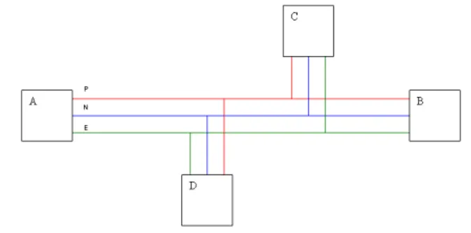
Figure 4. A simplified PLC system
For illustration, consider figure 4 showing a simplified PLC channel, where A, B, C and D are electric sockets. Let Hab, Hac and Had are the CTFs between the transmit socket A and receive sockets B, C and D respectively. When applying the TR technique at the transmit port A, the pre-processing filters
Dab, Dac and Dad are adapted to the transmission channel at the
intended receiver location only. At other locations along the transmission line, the pre-processing filter does not match the transmission channel. As a result, the local current intensity is lowered, and in turn, less power is radiated.
In addition, it should be noted that the improved SNR at the receiver contributed by TR technique can in turn allow lower power levels at the transmitter. This is particularly beneficial for PLC systems which are suffering from severe transmit power regulations.
A. PLC Channel Measurements
An extensive inhome PLC channel transfer function measurement campaign was launched by Orange Labs in several houses at Lannion. In total 144 real-life PLC channels were measured up to 100 MHz and grouped in nine classes according to mean channel attenuation [7].
0 1 2 3 4 5 6 7 8 9 10 x 107 -80 -70 -60 -50 -40 -30 -20 -10 0 Frequency Hz tr a n s fe r fu n c ti o n d B
Class models of the PLC transfer functions
class 1 class 2 class 3 class 4 class 5 class 6 class 7 class 8 class 9
Figure 5. Mean channel attenuation for a set of 144 measured CTFs divided into nine classes [7]
Figure 5 shows that there is a considerable amount of variability of channel attenuation. For example, class 1 channels offer attenuation less than 10 dB up to 70 MHz while class 9 channels exhibit an attenuation of around 53 dB in the same band. It should be noted that the middle classes 4, 5, 6 and 7 contain most channels.
B. Time-Reversal Performance Parameters
We defined two performance parameters for the evaluation of TR technique: Focusing Gain and Isolation Margin.
Focusing Gain
For illustration, consider the example of figure 4 which consists of three CTFs Hab, Hac and Had. To obtain the Focusing Gain, we apply TR on each CTF individually, as shown in figure 2. Then, we shift to time-domain by inverse fast Fourier transform (IFFT). Focusing Gain is defined as the difference in dB between the peaks of the CIR before and after TR.
Figure 6. Definition of Focusing Gain
Isolation Margin
For Isolation Margin, we apply the TR to an ensemble (instead of individual CTF) of CTFs (Hab, Hac and Had for example) having a common transmit socket as depicted in figure 7(a).
Figure 7(a). Block diagram of TR communication system with one transmit socket and multiple receive sockets
A signal passing through a pre-processing filter matched to the kth CTF is received clean and strong at the intended receiver k. This scenario corresponds to the diagonal entries in figure 7(b). Channel Transfer 1 2 3 .. k .. n 2 : 3 : : : k kk : : Pre-Processing Filter n nn
Figure 7(b). Time-reversal implementation matrix for an ensemble of n CTFs.
The non intended receivers, due to unmatched pre-processing filters, get a diminished and distorted version of the signal. This scenario corresponds to the off-diagonal entries in figure 7(b).
The Isolation Margin is defined as the difference between the diagonal entry and the highest off-diagonal entry for a column in figure 7(b).
Isolation Margin = CTFkk, after TR – max (CTFnk,after TR) (4) The column-wise analysis is more correct and meaningful as it treats a given CTFk with n pre-processing filters, each
normalized to unit power gain.
The definition of Isolation Margin is illustrated graphically in figure 8. It has to be noted that for calculating the Isolation Margin we have taken into account the magnitudes at time t=0.
Figure 8. Definition of Isolation Margin
C. Data Processing and Results
We calculated Focusing Gain for 144 CTFs and the results are shown in the CDF of figure 9. We find that a Focusing Gain of 6 dB is available in 75% of inhome PLC channels. This is an interesting and encouraging result, not only for the signal reception but especially from the EMC point of view. The Focusing Gain obtained by Time-reversal technique can be translated into reduced transmit power of PLC systems, hence preventing them from becoming a source of unwanted emissions.
Figure 9. CDF of Focusing Gain for 144 CTFs
Figure 10 shows the plot between Focusing Gain and the peak value of CIR magnitude. It is quite obvious from this figure that the Focusing Gain generally increases for weaker PLC channels. Therefore, Time-reversal technique offers a healing effect to highly attenuated channels. This can be explained by the fact that attenuated channels generally offer rich multipath conditions, where the TR is more effective.
Figure 10. Relationship between Focusing Gain and peak value of the CIR magnitude.
Evaluation of Isolation Margin was performed for CTF ensembles which had a common transmit socket as depicted in figure 7(a). Table 1 summarizes the Isolation Margin values obtained at measurement sites.
Site No. Tx Port Number of Channels
Mean Isolation Margin (dB) 1 19 2.72 2 6 13.27 1 3 7 7.16 1 6 5.66 2 2 6 7.64 1 13 3.58 3 2 15 2.41 4 34 3.48 5 15 5.07 6 22 6.95
Table 1. Mean Isolation Margin
Figure 11 shows the CDF of Isolation Margin for the group of 22 channels measured at the site no. 6. It demonstrates that almost 70% CTFs achieve an Isolation Margin of 6 dB. From the EMC point of view, Isolation Margin is an indicator of a reduction in interference level caused by a system to its ambience. Therefore, a PLC system with Time-reversal
technique is less disturbing for the neighboring systems which can be other PLC systems or DSL.
Figure 11. CDF of Isolation Margin for a group of 22 channels at site no. 6
V. CONCLUSIONS
The PLC systems are facing severe EMC issues of co-existence with amateur and commercial radio broadcasters. Such EMC problems may be solved by Time-Reversal technique. TR technique comprises of two steps: channel estimation and pre-filtering the information through TR filter before transmission. In this paper we defined two performance parameters: Focusing Gain and Isolation Margin. Then we evaluated these parameters for 144 real-life inhome PLC channels. The obtained results indicate that TR technique facilitates the PLC systems not to be source and victim of undesirable radio emissions, hence improving the PLC systems' electromagnetic compatibility.
REFERENCES
[1] Zimmermann, M. & Dostert, K. A multipath model for powerline channel. IEEE Transactions on Communications,
2002
[2] Lerosey Geoffroy. Retournement temporel d'ondes electromamgnetique et application à la télécommunicati-on en milieux complexes. Thèse à l'Université Paris-7, Décembre
2006
[3] Praho Brice et al. Restrictions related to the electromagnetic compatibility emission issue in power line communications. ISEF 2009, Arras, September 2009
[4] P. Pajusco, Pascal Pagani. On the use of uniform circular arrays for characterizing UWB Time Reversal. IEEE
Transactions on Antennas and Propagation, 2009
[5] Persefoni Kyritsi, PhD class on Adaptive Antennas,
Aalborg, December 2004
[6] 7th Framework Programme: ICT-213311 OMEGA, D3.2, "PLC Channel Characterization and Modelling", Dec. 2008. [7] Tlich, M.; Zeddam, A.; Moulin, F. & Gauthier, F. Indoor Power-Line Communications Channel characterization Up to 100 MHz—Part I: One-Parameter Deterministic Model IEEE
![Figure 1: Two steps of a Time-Reversal experiment in radio communication [5]](https://thumb-eu.123doks.com/thumbv2/123doknet/11658682.309515/2.892.490.800.694.795/figure-steps-time-reversal-experiment-radio-communication.webp)
![Figure 5. Mean channel attenuation for a set of 144 measured CTFs divided into nine classes [7]](https://thumb-eu.123doks.com/thumbv2/123doknet/11658682.309515/4.892.89.410.135.393/figure-mean-channel-attenuation-measured-ctfs-divided-classes.webp)


