HAL Id: hal-01867828
https://hal-mines-albi.archives-ouvertes.fr/hal-01867828
Submitted on 29 Jan 2019
HAL is a multi-disciplinary open access
archive for the deposit and dissemination of sci-entific research documents, whether they are pub-lished or not. The documents may come from teaching and research institutions in France or abroad, or from public or private research centers.
L’archive ouverte pluridisciplinaire HAL, est destinée au dépôt et à la diffusion de documents scientifiques de niveau recherche, publiés ou non, émanant des établissements d’enseignement et de recherche français ou étrangers, des laboratoires publics ou privés.
To cite this version:
Laure Moretti, Gilles Dusserre, Bruno Castanié, Philippe Olivier. Analysis of the influence of the adhesive on process distortions of the co-bonded stringer foot specimens. ECCM18 - 18th European Conference on Composite Materials, Jun 2018, Athènes, Greece. 8 p. �hal-01867828�
L. Moretti, G. Dusserre, B. Castanié and P. Olivier
ANALYSIS OF THE INFLUENCE OF THE ADHESIVE ON PROCESS
DISTORTIONS OF CO-BONDED STRINGER FOOT SPECIMENS.
Laure Moretti1,2, Gilles Dusserre1 , Bruno Castanié2 and Philippe Olivier2
1Institut Clément Ader (ICA), Université de Toulouse, CNRS, Mines Albi, UPS, INSA,
ISAE-SUPAERO, Campus Jarlard, 81013 Albi CT Cedex 09, France Email: laure.moretti@mines-albi.fr
Email: gilles.dusserre@mines-albi.fr
2Institut Clément Ader (ICA), Université de Toulouse, CNRS, Mines Albi, UPS, INSA,
ISAE-SUPAERO, 3 rue Caroline Aigle, 31400 Toulouse, France Email: bruno.castanie@ insa-toulouse.fr
Email: philippe.olivier@iut-tlse3.fr
Keywords: Composite, adhesive, co-bonding, distortions, simulation
Abstract
Process induced distortions prediction is a major issue for structural parts like self-reinforced panels. They may cause important displacements for parts of large dimension and compromise the quality of the assembly. Development of numerical process models is necessary to avoid the expensive and time-consuming trial-and-error approach. Various numerical models exist to predict those distortions. However, regarding co-bonded integrated structures, the influence of the adhesive film on final distortions is often ignored. The aim of this study is to simulate process induced distortions for co-bonded integrated structures and to understand the contribution of the adhesive film on those distortions. To do that, Finite Element Analysis (FEA) simulations are used. To be able to set up the FEA, thermal and mechanical properties are characterized for the epoxy-carbon fiber prepreg M21EV/IMA and the epoxy adhesive film FM300-M. Various models and parameters associated are determined and used to describe thermal and mechanical behaviour of both materials. Those models and properties are then employed to implement a FEA on ABAQUS using FORTRAN subroutines. The numerical model simulates process induced distortions during an autoclave cycle for co-bonded parts. Using this model, we aim to define stringer foot specimen geometry and lay-up to enable an experimental/numerical comparison.
1. Introduction
During their cure, composite parts are submitted to several multi-physical phenomena. Those phenomena may cause residual constraints and deformations which will modify the final geometry of the part. The part obtained has always some differences compared to the initial mould. Those variations of geometry are a main issue for parts of large dimensions were the displacements caused by small deformations can be large. Those deformations can also compromise the quality of the assembly of co-bonded integrated structures.
It is possible to compensate the deformations by modifying the initial mould. However, the trial and error iteration process to do so can be costly and time consuming. Therefore, efficient simulation methods are needed to avoid this costly process and to be able to produce directly the right compensated mould.
It is possible to classify the parameters responsible for deformations among two main groups : intrinsic and extrinsic parameters [1]. Intrinsic parameters are directly linked to material properties or
L. Moretti, G. Dusserre, B. Castanié and P. Olivier
the reticulation of the resin. Extrinsic parameters on the other hand are linked to external causes like the interaction with the tool or the conditions of the process used for the cure.
Distortions are then caused by complex and diversified parameters and phenomena. In the case of co-bonding other considerations must be taken in account. The adhesive has a different composition from the composite. Its kinetics and mechanical behaviours are different. Without fibers its thermal and chemical shrinkage are more important. The adhesive film may then have an influence on the final distortions of the assembled part. Its behaviour and its capacity to transfer deformations between the various parts of an assembly must then be understood to simulate properly the distortions of the final part.
The materials used in this study are the M21EV/IMA prepreg provided by Hexcel and FM300-M adhesive film. Both materials have an epoxy matrix.
2. Thermo-chemical model
2.1. Kinetic of reaction: modified Kamal Sourour model
Kinetic models can be divided in two main groups: phenomenological and mechanistic models. Phenomenological models describe the kinetic behaviour of materials in an empirical way. Mechanistic models describe every chemical reaction, are complex and need a very long and complete characterization and identification of parameters. In our study we decided to privilege the easier to use phenomenological models.
For the study of the M21 resin family two main autocatalytic phenomenological models are used in the literature : the Bailleul model [2] and the modified Kamal Sourour model [3], [4]. In our case the modified Kamal Sourour model presented in the following equations (Eq. (1) and Eq. (2)) was used.
𝑑𝛼 𝑑𝑡 = (𝑘1+ 𝑘2∙ 𝛼 𝑚)(𝛼 𝑚𝑎𝑥− 𝛼)𝑛 (1) 𝑘𝑖 = 𝐴𝑖∙ exp(− 𝐸𝑎𝑖 𝑅 ∙ 𝑇) (2)
𝛼 is the degree of cure, m and n the partial orders of reaction, 𝐸𝑎𝑖 the activation energies and 𝑘𝑖 the
reaction constants.
This model is applied to the M21EV/IMA prepreg and the FM300-M epoxy adhesive. To characterize the kinetic behaviour of the materials we performed DSC and MDSC measurements using a DSC TA instrument Q100.
In a first step, the parameters of the law describing the evolution of the maximum degree of cure 𝛼𝑚𝑎𝑥 must be identified. The 𝛼𝑚𝑎𝑥 for various degrees of cure are obtained measuring the residual enthalpy by dynamic DSC after isotherms at various temperatures and applying the following equation (Eq. 3).
𝛼𝑚𝑎𝑥= 1 − Δ𝐻𝑟𝑒𝑠𝑖
Δ𝐻𝑡𝑜𝑡
(3)
Δ𝐻𝑟𝑒𝑠𝑖 is the residual enthalpy and Δ𝐻𝑡𝑜𝑡 is the total enthalpy.
A polynomial law is found suitable to describe the behaviour of 𝛼𝑚𝑎𝑥 for both materials. The confrontation with our experimental data is available in the Fig.1.
L. Moretti, G. Dusserre, B. Castanié and P. Olivier
Figure 1. Maximum degree of cure for various isotherms
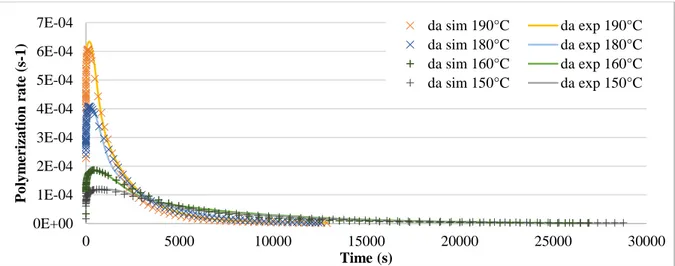
Various dynamic and isothermal DSC measurements are then proceeded to determine the other parameters of the Kamal Sourour law. A Matlab algorithm using lsqnonlin, a nonlinear least-squares solver, is used to extract the six remaining parameters from the experimental data obtained by DSC. The confrontation between the results of the simulations of the polymerization rates using the parameters identified and some of our isothermal and dynamic DSC measurements is available in Fig. 2, Fig. 3 and Fig.4.
Figure 2. Comparison between experimental measurements and simulations of the M21EV/IMA
kinetic behaviour for various isotherms
Figure 3. Comparison between experimental measurements and simulations of the FM300-M kinetic
behaviour for various isotherms Polynomial law R² = 0,9883 Polynomial law R² = 0,9926 0% 20% 40% 60% 80% 100% 25 75 125 175 225 Deg re e o f cure ( %) Temperature (°c) FM300M M21EVIMA 0E+00 1E-04 2E-04 3E-04 4E-04 5E-04 6E-04 7E-04 0 5000 10000 15000 20000 25000 30000 P o ly m er iza tio n ra te (s -1) Time (s) da sim 190°C da exp 190°C da sim 180°C da exp 180°C da sim 160°C da exp 160°C da sim 150°C da exp 150°C 0E+00 1E-03 2E-03 3E-03 4E-03 5E-03 0 1000 2000 3000 4000 5000 6000 7000 8000 P o ly m er iza tio n ra te (s -1) Time (s) da sim 170°C da exp 170°C da sim 180°C da exp 180°C da sim 160°C da exp 160°C da sim 150°C da exp 150°C
L. Moretti, G. Dusserre, B. Castanié and P. Olivier
Figure 4. Comparison between experimental measurement and simulation of the M21EV/IMA kinetic
behaviour at 1 K/min
2.2. Temperature of glass transition: Di Benedetto model
The temperature of glass transition depends of the polymerization degree of the thermoset. To describe the evolution of this transition temperature we used the Di Benedetto model developed by Pascault and Williams [5] (Eq. (4) and (5)).
𝑇𝑔− 𝑇𝑔0 𝑇𝑔∞− 𝑇𝑔0 = 𝜆 ∙ 𝛼 1 − (1 − 𝜆) ∙ 𝛼 (4) 𝑇𝑔= 𝜆 ∙ 𝛼 1 − (1 − 𝜆) ∙ 𝛼∙ (𝑇𝑔∞− 𝑇𝑔0) + 𝑇𝑔0 (5)
𝑇𝑔∞ and 𝑇𝑔0 are the glass transition temperatures for the respectively fully cured and uncured polymer, 𝛼 is the degree of cure and 𝜆 is a constant that needs to be identified.
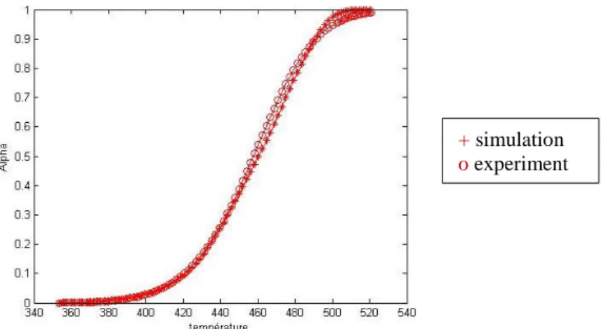
Once again DSC and MDSC measurements are performed on both materials using a DSC TA instrument Q100. 𝑇𝑔∞, 𝑇𝑔0 and 𝑇𝑔 for various degrees of cure are measured. 𝜆 is identified using GRG nonlinear excel solver to minimize (𝑇𝑔𝑒𝑥𝑝− 𝑇𝑔𝑠𝑖𝑚)
2
with a multistart of 100000. Confrontations between simulation results and experimental measurements are shown in Fig. 5 for both materials.
(a) (b)
Figure 5. Comparison between experimental measurement and simulation of the M21EV/IMA (a) and
FM300-M (b) glass transition temperature evolution during the cure 0 50 100 150 200 250 0 0,5 1 Glass tr an sitio n tem p er atu re (° C) Degree of cure (%) ---sim
×
exp 0 20 40 60 80 100 120 140 160 180 0 0,5 1 Glass tr an sitio n tem p er atu re (° C) Degree of cure (%) + simulation o experiment --- sim×
expL. Moretti, G. Dusserre, B. Castanié and P. Olivier 2.3. Thermo-chemical simulation results
Once the various parameters of the kinetic laws are identified those behaviour laws are implemented on a FEA simulation on Abaqus. The thermo-chemical behaviour laws are implemented thanks to various FORTRAN subroutines.
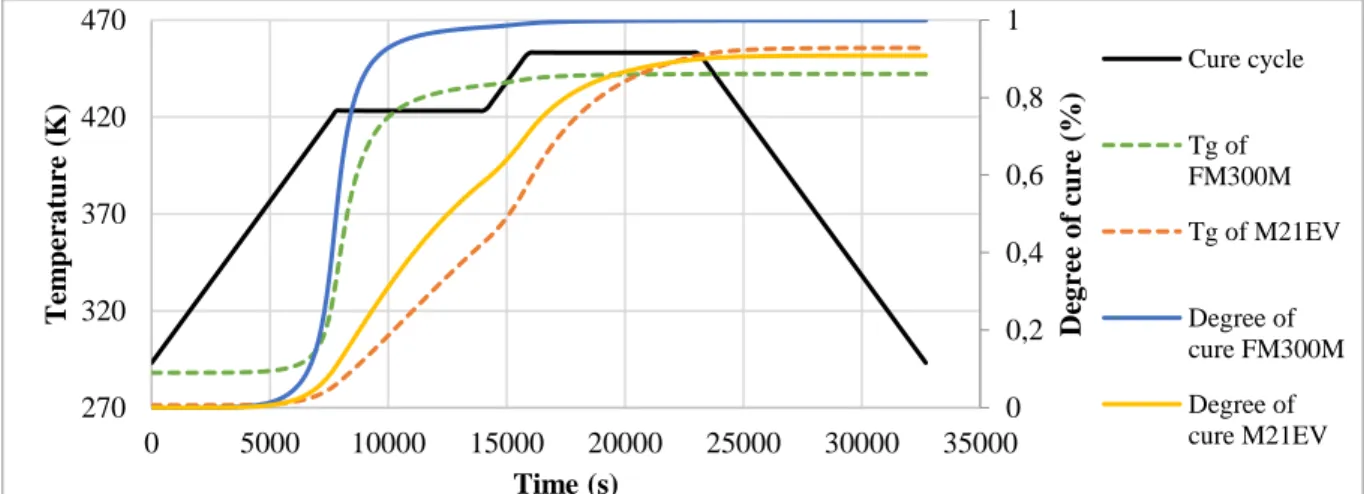
In the Fig. 6 a FEA simulation of a stringer-foot specimen inspired from the work of Bertolini et al. [6] is shown. The specimen is made of M21EV/IMA co-cured with FM300-M adhesive and the FEA simulation uses the thermo-chemical model developed above. As it can be seen in Fig. 7 presenting the results of the simulation, the adhesive is polymerizing far more quickly than the M21EV. Its behaviour is then expected to be quite different from the M21EV and may induce distortions. Moreover, the temperature of the second step of the cure is exceeding the 𝑇𝑔∞ of the FM300-M, this is also going to induce differences of behaviour between the two materials.
Figure 6. 3D and 2D FEA simulation results for co-cured M21EV/IMA laminates with FM300M
Figure 7. FEA simulation results for co-cured M21EV/IMA laminates with FM300M
3. Mechanical simulation 3.1. CHILE constitutive law
To describe the mechanical behaviour of our materials we used a Cure Hardening Instantaneous Linear Elastic (CHILE) model. This model developed by Johnston [7] is initially inspired from the work of Bogetti et Gillespie [8] in 1992. In this model the elastic properties can evolve during the simulation of the cure, but at each time step the material behaviour is linear elastic. The constitutive CHILE model is described by the following equations (Eq. (6) and Eq. (7)).
0 0,2 0,4 0,6 0,8 1 270 320 370 420 470 0 5000 10000 15000 20000 25000 30000 35000 Deg re e o f cure ( %) T em pera ture (K ) Time (s) Cure cycle Tg of FM300M Tg of M21EV Degree of cure FM300M Degree of cure M21EV
L. Moretti, G. Dusserre, B. Castanié and P. Olivier 𝐸𝑟= { 𝐸𝑟0+ 𝑇∗+ 𝑇 𝐶1∗ 𝑇𝐶2∗ − 𝑇𝐶1∗ 𝐸𝑟∞ (𝐸𝑟∞− 𝐸𝑟0)𝑇𝐶1∗ < 𝑇∗< 𝑇𝐶2∗ 𝑇∗> 𝑇 𝐶2∗ (6) 𝑇∗= 𝑇 𝑔− 𝑇 = 𝜆 ∙ 𝛼 1 − (1 − 𝜆) ∙ 𝛼∙ (𝑇𝑔∞− 𝑇𝑔0) + 𝑇𝑔0− 𝑇 (7) 𝐸𝑟∞is the relaxed modulus at T >> Tg and 𝐸𝑟0 is the unrelaxed modulus at T << Tg. 𝑇𝐶1∗ and 𝑇𝐶2∗ are T*
critical values at the beginning and at the end of vitrification.
The CHILE constitutive law is implemented in Abaqus thanks to an UMAT subroutine.
3.2. Thermal and chemical expansion
Thermal and chemical expansion behaviour are implemented in the FEA model using an UEXPAN FORTRAN subroutine. The coefficient of thermal expansion (CTE) is acting with the temperature increment and the coefficient of chemical shrinkage (CCS) is acting with the degree of cure increment (Eq. 8). The chemical shrinkage coefficient used was obtained in the literature [9] and the CTE was measured thanks to a TMA Perkin Elmer. The CTE is implemented as dependant of the state of the resin (visquous, rubbery or glassy) (Eq. 9).
𝐸𝑋𝑃𝐴𝑁 = 𝐶𝑇𝐸 ∙ dT + CCS ∙ dα (8) 𝐶𝑇𝐸𝑖= { 𝐶𝑇𝐸𝑖𝑙, 𝛼 < 𝛼𝑔𝑒𝑙𝑎𝑛𝑑𝑇 ≥ 𝑇𝑔(𝛼) 𝐶𝑇𝐸𝑖𝑟, 𝛼 ≥ 𝛼𝑔𝑒𝑙𝑎𝑛𝑑𝑇 ≥ 𝑇𝑔(𝛼) 𝐶𝑇𝐸𝑖𝑔,𝑇 < 𝑇𝑔(𝛼) (9)
With i=1,2,3 corresponding of each orientation of orthotropic CTE. 𝛼𝑔𝑒𝑙 is the degree of cure at the onset of gelation.
3.3. Thermo-mechanical simulation results
The thermo-mechanical model developed is implemented on Abaqus. The results of the CHILE formulation for the evolution of the modulus are compared with DMA measurements made by Ch. Paris for a M21 based prepreg [3] (Fig. 8). This material behaviour is supposed to be very similar to the M21EV. To get closer from the real behaviour of the material the CHILE model will soon be modified to have two sloping domains instead of one.
L. Moretti, G. Dusserre, B. Castanié and P. Olivier
(a)
(b)
Figure 8. Confrontation between FEA simulation of the modulus evolution (a) and experimental
values obtained from the literature [3] for M21/T700 (b) during a DMA test
Finally, the model coupling the thermo-chemical and the mechanical models developed in this study is implemented. Some of the results obtained for an asymmetric laminate are illustrated on the Fig. 9.
Figure 9. FEA simulation results for asymmetric M21EV/IMA laminate
4. Conclusions
In this study a methodology has been developed to simulate the distortions induced during the curing of bonded parts by autoclave. The model obtained takes account of temperature and degree of cure gradients induced during curing and their impacts on thermal expansion, chemical shrinkage and mechanical properties of the laminate and the adhesive. This model must now be enriched with a simulation of the interaction between the tool and the composite part. To do so a model strongly inspired from the work of L. Mezeix et al. [10, 11] will be coupled with the thermo-mechanical model developed in this article.
The final model will be confronted with experimental measures of deformations on stringer foot specimen with and without adhesive. This last step will allow to quantify more accurately the influence of the adhesive on distortions and to validate the model.
References
[1] D. Stefaniak, E. Kappel, T. Spröwitz, and C. Hühne, “Experimental identification of process parameters inducing warpage of autoclave-processed CFRP parts,” Composites Part A: Applied Science and Manufacturing, vol. 43, no. 7, pp. 1081–1091, Jul. 2012.
-100 0 100 200 300 400 M o d u lu s (M P a) Temperature (°C) 293 343 393 443 493 0 50000 100000 150000 200000 0 10000 20000 30000 T em pera ture (K ) M o du lus Time (s)
L. Moretti, G. Dusserre, B. Castanié and P. Olivier
matrix composites,” Composites Part A: Applied Science and Manufacturing, vol. 41, no. 1, pp. 108–115, Jan. 2010.
[3] C. Paris, “Étude et modélisation de la polymérisation dynamique de composites à matrice thermodurcissable,” INPT, 2011.
[4] Y. Ledru, “Etude de la porosité dans les matériaux composites stratifiés aéronautiques,” Génie Mécanique, Mécanique et matériaux, Univerté de Toulouse, 2009.
[5] J. P. Pascault and R. J. J. Williams, “Glass Transition Temperature Versus Conversion Remationships For Thermosetting Polymers,” Journal of Polymer Science : Part B, vol. 28, no. 1, pp. 85–95, Jan. 1990.
[6] J. Bertolini, B. Castanié, J.-J. Barrau, and J.-P. Navarro, “Multi-level experimental and numerical analysis of composite stiffener debonding Part 1 : Non-specific specimen level.,” Composite Structures, vol. 90, no. 10, pp. 381–391, 2009.
[7] A. Johnston, R. Vaziri, and A. Poursartip, “A Plane Strain Model for Process-Induced Deformation of Laminated Composite Structures,” Journal of Composite Materials, vol. 35, no. 16, pp. 1435–1469, Jan. 2001.
[8] T. A. Bogetti and J. W. Gillespie Jr, “Process-induced stress and deformation in thick-section thermoset composite laminates,” Journal of composite materials, vol. 26, no. 5, pp. 626–660, 1992.
[9] Y. Nawab, “Characterization and modelling of cure dependant properties of thermoset composites - Application to the simulation of residual stresses.,” Génie Mécanique, Université de Nantes, Saint Nazaire - CRTT, 2012.
[10] M Fiorina, A Seman, B Castanie, KM Ali, C Schwob, L Mezeix. " Spring-in prediction for carbon/epoxy aerospace composite structure " Composite Structures vol 168, pp 739-745, 2017 [11] L Mezeix, A Seman, MNM Nasir, Y Aminanda, A Rivai, B Castanié, P Olivier, KM Ali
"Spring-back simulation of unidirectional carbon/epoxy flat laminate composite manufactured through autoclave process" Composite Structures Vol 124, pp 196-205, 2015
![Figure 8. Confrontation between FEA simulation of the modulus evolution (a) and experimental values obtained from the literature [3] for M21/T700 (b) during a DMA test](https://thumb-eu.123doks.com/thumbv2/123doknet/11524824.294972/8.893.113.794.127.381/figure-confrontation-simulation-modulus-evolution-experimental-obtained-literature.webp)
