1
DETERMINATION OF THE LOAD BEARING CAPACITY OF COMPOSITE FLANGES
FOR AIRCRAFT ENGINE CASING APPLICATION: GENERAL METHODOLOGY AND
DESIGN OF TESTING DEVICES SUPPORTED BY SIMULATION
M. Bruyneel1,2, B. Crevits1, Olivier R.1, C. Vroomen3, E. Racle4, T. Germain4, J. Gallais 4, D. Verhelst4
1GDTech Engineering (Global Design Technology), Liège, Belgium 2University of Liège, Aerospace & Mechanics Dept, Liège, Belgium
3University of Liège, Architecture, Geology, Environment & Construction Dept, Liège, Belgium 4SAFRAN Aero Boosters, Liège, Belgium
Michael.bruyneel@gdtech.eu (corresponding author)
Benoit.crevits@gdtech.eu Richard.olivier@gdtech.eu c.vroomen@ulg.ac.be elie.racle.ext@techspace-aero.be Thomas.germain@techspace-aero.be jacques.gallais-hamonno@techspace-aero.be damien.verhelst@techspace-aero.be
SUMMARY
The context of this paper is the verification of the load bearing capacity of composite flanges used in engine aircraft components. These flanges are considered as important details of the full composite casing and are therefore studied at a specific stage of the pyramid of tests, the goal being to determine, by tests and simulation, their structural behavior and establish the material allowables that will be used later in the sizing process at the casing level. Seeing the particular shape of the flanges and the different loading scenarios, specific tooling devices are designed to be adapted on standard testing machines. Finite element models are used to support the development of the tooling. In this paper, the test campaign is described, and the methodology used for designing the tooling for the testing is explained. It is shown how, from the coupon level, the material properties of the composite are determined, not only for the linear but also for the non-linear behavior including damage and plasticity properties. This information is used in a set of finite element models of different fidelity levels that are used to estimate the load capacity of the composite flanges. The prediction of the load capacity is then used in a finite element model to validate the design of the developed specific testing tooling devices. As the test campaign on the flanges is still running when writing this paper, the results on the physical tests are not reported here, but will be presented at the conference and in future articles.
KEYWORDS
: composites, modelling, tooling, testing, damage, parameter identification, pyramid of tests, virtual testing2
1. INTRODUCTION
In this paper, we consider fiber reinforced composite structures made up of plies including continuous carbon fibers embedded in a polymeric matrix, and forming a laminate (stack of plies), as illustrated in Figure 1.
Figure 1. A laminate made of orthotropic plies
This kind of material is used more and more, seeing its high stiffness and strength to density ratios. Initially applied to aero-structures (see the recent success of the Airbus A350 XWB and the Boeing 787 with up to 60% of the total mass made of such materials), polymer matrix composites are now also employed in automotive and energy industries. In this paper, carbon fibers are used in the design of an aircraft engine casing (Figure 2). Very few publications are available on the topic [1].
Figure 2. Outer casing to design with carbon fibers
Composite design is based on the pyramid of tests [2], illustrated in Figure 3 in the specific case of the present application. Starting from the coupon level, the material properties are determined and the parameters entering the material models for the finite element analysis are identified. At this stage, standard testing is used, on standard machines [3]. Based on this information, stage 2 can be reached, where some details are studied in order to determine their allowables. The flanges studied in this paper are located at that stage, and the specific configuration of a radial flange is considered. Moving up in the pyramid allows reaching the final stage, corresponding to the full scale casing. Even if the pyramid of Figure 2 is only populated with finite element models, it is obvious that in practice both physical and virtual
3
testing co-exist. At the first stage, coupon testing is used to identify the parameters of the material models, and at the last stage of the pyramid the mechanical performances of the physical casing will be first validated with its digital twin to be sure to pass the tests on the physical prototype. In between, simulation is a companion of the physical testing, that is used to validate different configurations of the elements and the sub-components.
Figure 3. The pyramid of tests used for the casing – virtual testing
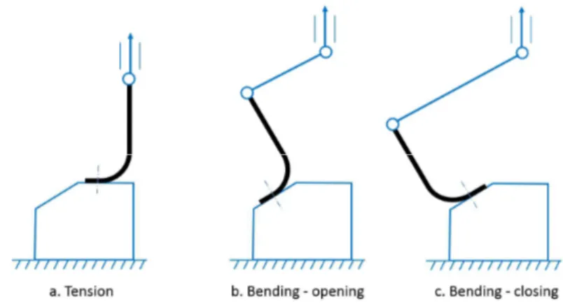
According to the loads acting on the casing, different configurations of the flanges can be studied. Concentrating on radial flanges, Figure 4 illustrates three configurations that are considered in the study: flange in tension and flange in bending.
Figure 4. The different configurations/loading of the flange studied here
The tests on the flanges (up to their final failure) are conducted on standard machines, available in the M&S (Materials and Structures) laboratory of the University of Liège (Figure 5). Even if the paper will focus on static load cases only, fatigue is also considered in the test campaign. Since the tests on the flanges are conducted as the paper is written, the results are not provided here but will be presented at the conference and published later elsewhere. Different test machines with different loading capacities are available. In order to determine which machine should be used, finite element models of the flanges are developed to estimate their load bearing capacity. The material properties used in these models come from the identification done at the coupon level (Figure 3). With this information, a testing machine can be selected, and the specific tooling can then be designed (and validated with the finite element approach) taking into account the specific interface of the selected machine.
4
In this paper, the finite element analyses are conducted with the SAMCEF finite element software. The BACON module of SAMCEF and the NX CAD/CAE environment are used for the modeling [4].
Finally, the reader will understand that for confidentiality reasons the numerical values of the material properties, the amplitudes of the loads, the safety margins and some details of the tooling are not provided here.
Figure 5. Some of the machines available at the Ulg-M&S laboratory
2. IDENTIFICATION AT THE COUPON LEVEL
Based on the pyramid of tests described in Figure 3, the material properties are determined with standard tests at the coupon level. Both inter and intra-laminar properties are identified. For the inter-laminar properties, ILSS and ILNS tests are conducted in order to determine the strengths in shear and in tension, respectively, which represent values of the stress leading to the initiation of a crack propagation at the interface between the plies (Figure 6). DCB and ENF tests allow determining the delamination behavior and provide the values of the inter-laminar fracture toughness GIC and GIIC (Figure 7). The notations for the inter-laminar behavior are given in Figure 8.
5
Figure 7. Testing for the inter-laminar toughness
Figure 8. Behavior at the interface between two plies: peel and shear stresses
In both cases of Figures 6 and 7, interface elements are used in a finite element model made up of solid shell elements. These interface elements are defined between each ply. Each ply is represented by one finite element on its thickness (Figure 9).
Figure 9. Meshes used for the ILNS and ILLS models, with dimensions according to the standards
For DCB and ENF, the inter-laminar crack propagation must be modelled. A specific cohesive law is therefore included in the interface elements, and so cohesive elements are used. The potential associated to the interface elements is given by (1), where the three relevant components of the strain tensor are considered (Figure 8).
6
In (1), ki0 (i=I,II,III) represent the stiffness associated to the normal strain and to the two shear effects. Damage variables di (i=I,II,III) are defined for each of the three crack solicitation modes as in Figure 8 (opening, shear and sliding modes, for modes I, II and III, respectively). The value of the damage variable di ϵ [0,1] increases as a function of a thermodynamic force Yi which is the derivative of the potential (1) with respect to the corresponding damage variable. The thermodynamic force represent the effect of the loading in the corresponding mode. For mixed mode loading, the damage evolution is related to the three inter-laminar fracture toughness GIc, GIIc and GIIIc via an equivalent thermodynamic force Y given in (2). It is considered that the three damage variables have the same evolution during the loading, and a single damage variable d associated to Y is then used to represent delamination. In SAMCEF, depending on how d is related to Y, either a polynomial, a bi-triangular or an exponential constitutive law is used in the interface element. More details can be found in [5,6].
𝑌 = sup 𝐺 + + (2)
For the intra-laminar properties [7,8], classical tests are conducted in order to determine the elastic properties (E1, E2, G12 and 12) and the strengths, noted XT, XC, YT, YC and S for the longitudinal, transversal and shear directions. As damage modeling is investigated in this study, loading/unloading cycles of increasing amplitude are performed during the tensile test on a [45]n stacking sequence. This allows us to use the material model based on Continuum Damage Mechanics (CDM) proposed in [7] and validated in [8]. In this model (expressed here for the plane stress conditions), damage variables impacting the behavior in the fibers (d11 and d22), and in the matrix (d12) are defined, and penalize the initial elastic stiffnesses:
𝑒 =
( ) − 𝜎 𝜎 + ( ) + ( ) (3)
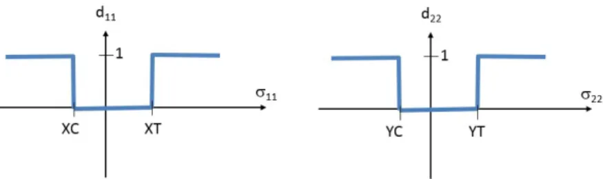
E10, E20 and G120 are the initial elastic moduli (that is, before any damage occurs). The damage variables evolve between 0 (no damage) and 1 (fully damaged) as a function of thermodynamic forces defined as the derivatives of the potential ed with respect to each damage variable. For the evolution of the damage in the fibers, the thermodynamic force can be related to the corresponding strengths XT, XC, YT, YC, and the behavior is assumed to be brittle and linear: the damage is equal to zero and reaches a value of 1 when the stress in the fiber direction is equal to the strength (Figure 10).
Figure 10. Evolution of the damage in the fiber directions For the damage inside the matrix, we have the following equation.
𝑌 = =
( ) (4)
An equivalent thermodynamic force is used, which combines the effects along the fibers and in the matrix. There, a clear non-linear behavior can be observed, as illustrated in Figure 11.
7
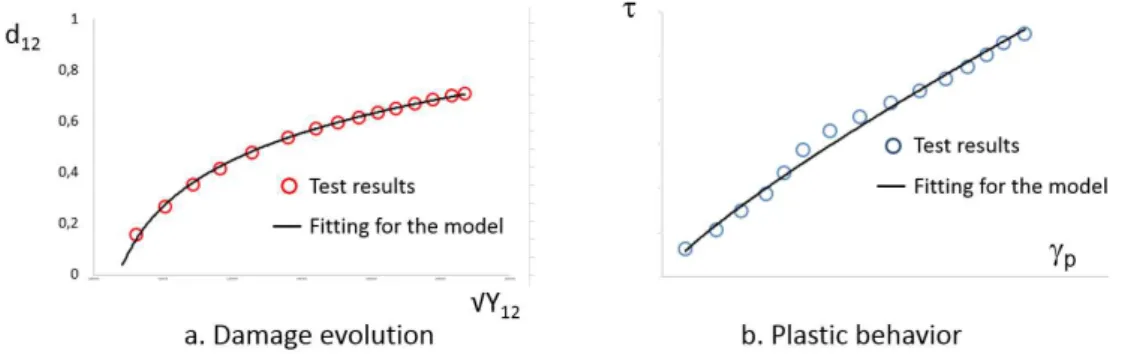
The behavior in shear is globally highly non-linear. On top of that, damage appears as a loss of stiffness identified during the unloading phases. Finally, permanent deformation is also observed after unloading, and therefore plasticity is taken into account in the material model. Based on the test results, the parameters of the damage model of [7] are identified. It is done by a fitting on the evolution of the damage and on the hardening curve coming from the experimental results (Figure 12).
Figure 11. Test result for the [45]n, submitted to loading/unloading cycles
Once the parameters are identified, the simulation can be run in order to check that the model is able to reproduce the right material behavior observed in Figure 11. The model is built with multi-layer solid elements. The tabs are also modeled. In Figure 13, it is seen that the simulation (red and blue curves, corresponding to 2 different elements in the finite element model) is able to reproduce the global behavior of the coupon. The evolution of the damage during the loading is also provided. It is clear that the damage will appear as a matrix cracking along the fibers oriented at 45° and -45°.
8
Figure 13. Comparison between test and simulation for the tensile test on a [45]n coupon
3. RADIAL FLANGE IN TENSION
3.1. Determination of the failure loads
Knowing the dimensions of the flange and the material (material properties identified at the coupon level, and specified stacking sequence made up of plies with conventional orientations), a representative finite element model can be developed and used to estimate the failure load and scenario (either first a failure of the fasteners and then of the composite; or a failure of the composite first). Models with different fidelities can be defined. In Figure 14, detailed models including the modeling of the radius block (load spreader) are illustrated.
Figure 14. Detailed finite element models of a flange with its fasteners
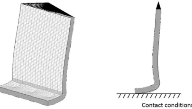
In Figure 15, the holes (3 in this case) for the fasteners are not modeled and the nodes at the corresponding locations are simply locked in order to represent the global kinematic effect of the fasteners and to avoid rigid body modes. Such a modeling will lead to spurious high stress values in the vicinity of the locked nodes. Therefore, the stresses at these locations will not be taken into account when analyzing the results. Rigid-flexible contact conditions are defined in order to represent the correct kinematic of deformation. Solid shell elements are used, with one element on the thickness of each ply.
9
Figure 15. Model of the flange without the fasteners modeled
A linear static analysis is conducted, and the Tsai-Wu criterion is evaluated in each ply. Figure 16 and 17 illustrate some results. In Figure 16, it is seen that the contact conditions are well respected, and that a curvature appears in the deformed structure, as the loading direction is fixed. This curvature will influence the stress state in each ply, as illustrated in Figure 17, where the red zones indicate a large value of the Tsai-Wu criterion, and the white zones a value that is above the saturation value used in the scale. As expected, the larger values of the Tsai-Wu are observed at the fastener locations, as the modeling introduces there a singularity. Moreover, it is noted that for some plies (plies 3 and 10 in Figure 17), the value of the Tsai-Wu criterion is below the limiting value, but for others large values appear at the corner (in the radius) where the curvature is high, which is clearly the critical location.
Figure 16. Deformation of the flange without the fasteners modeled (amplification for the deformation = 5)
10
This simple linear analysis allows to estimate the amplitude of the load that will lead to the failure of the composite flange. Based on this information, and considering a safety margin factor, an appropriate test machine (Figure 5) is selected. It is to be noted that the Classical Lamination Theory (CLT) implemented in a FORTRAN program was used to estimate the failures of the different plies in a flat laminate (no radius, only the vertical part of the flange) made up of the same stacking sequence as the one of the model in Figure 15. The results, confronted to an equivalent finite element model, showed much smaller values of the Tsai-Wu criterion. This together with the evidence in Figure 17 on the location of the maximum values of Tsai-Wu in the radius, indicate that the full flange and its correct kinematic must be modelled to get accurate results.
3.2. Design and validation of the tooling
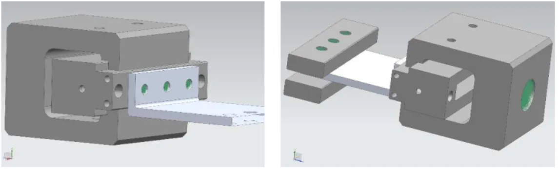
The goal of developing a specific tooling to adapt on a standard test machine is to make it possible to conduct testing on a specific element (see Figure 3). The design of (a part of) the tooling is illustrated in Figure 18.
Figure 18. Design of the tooling for the specific test on the flange
Based on the design of the tooling in Figure 18, a finite element model is developed in order to check its stiffness and strength. It is indeed important to develop a tooling that has a sufficient stiffness, especially because contacts must be satisfied in a correct way. Moreover, it is asked to avoid plasticity (or anyway tolerate small amounts of localized plasticity) that would lead to permanent deformations modifying the shape of the tooling.
Different meshes were developed, with different refinements, and convergence studies were conducted. Figure 19 illustrates a model including a mix of tetrahedral elements of degree 1 and degree 2, the degree 2 elements being located in the contact zones and in the radii in order to capture the stresses in an appropriate way. The flange is also modelled with tetrahedral elements, with an equivalent stiffness. The model includes 2,084,539 elements, 2,546,023 degrees of freedom (including 16,229 dof for the contact conditions). The failure load determined previously, multiplied by a safety margin, is applied on the model.
11
Figure 19. Finite element model of the tooling
A finite element result is illustrated in Figure 20. Besides the fictitious high stresses observed at the fasteners location not modelled but replaced by rigid body elements in the model, the relevant hot spots are located in the radii and at the transition between contact/non-contact zones. A sensitivity analysis study on the mesh density revealed that these last high stress values correspond actually to a singularity in the model, and are therefore not physical. An amplified deformation under the loading is illustrated in Figure 21.
Figure 20. Stress level in the tooling
Figure 21. Amplified deformation of the flange in the tooling under the loading
4. RADIAL FLANGE IN BENDING
4.1. Determination of the failure loads
A first model has been developed in order to reproduce the effects of the bending on the flange. Kinematic joints (hinges) and rigid bars are added to the finite element mesh of the
12
composite component of Figure 15, in order to reproduce the mechanism and its kinematics. Here the loading of Figure 4b (bending in opening) is considered.
Figure 22. Model of the flange under bending conditions
This model is used to determine the failure load of the flange and the maximum lateral force acting on the machine, knowing that in practice this lateral force must be limited. Some results are given in Figures 23 to 26. In Figure 23, a displacement is imposed on the top node (Figure 22), and the resulting values of the Tsai-Wu criterion are provided. Figure 24 illustrates the successive configurations of the component during the loading.
Figure 23. First results for the model of the flange under bending conditions: Tsai-Wu (linear static analysis)
Non-linear material properties including the information on damage and plasticity obtained in Section 2 can be used, in order to check the risks for delamination and intra-laminar damage such as fiber breaking, matrix cracking and de-cohesion between fibers and matrix. In Figures 25 and 26, representative results are used to estimate the critical plies and interfaces.
13
Figure 24. First results for the model of the flange under bending conditions: displacements and deformations (non-linear geometric analysis – linear material)
4.2. Design and validation of the tooling
With the model developed in Section 4.1, the ultimate load of the composite flange can be estimated. The design of the specific tooling is under development, and will be presented elsewhere.
Figure 25. First results for the model of the flange under bending conditions: damage in shear d12 in the plies (non-linear geometric analysis – non-linear materials)
Figure 26. First results for the model of the flange under bending conditions: delamination at interfaces between the plies (non-linear geometric analysis – non-linear materials)
14
5. CONCLUSIONS
First steps in the design of specific tooling for testing of composite flanges for aircraft engine applications have been presented. First, the general design methodology based on the pyramid of tests has been defined. The flanges are considered as important elements that must be studied separately in order to 1/ determine allowables seeing their specific geometry and connections to the casing, and 2/design and size the tooling for their physical testing. The principle for the parameter identification of the material models for inter and intra-laminar damages has been explained and illustrated. The finite element model for the flange in tension has been presented, and a design of the tooling to be used for the testing of the corresponding physical prototype has been described. First model and results for the flange under bending conditions have been presented. Linear and non-linear analysis (including geometric and material non linearities, as well as contacts) were conducted with SAMCEF. The test campaign on the flanges is running when writing this paper, and the corresponding results will be presented at the conference and in future articles.
6. ACKNOWLEDGEMENTS
The results presented in this paper were obtained in the frame of the ICOGEN project. The support of the Walloon Region of Belgium and of the Aerospace cluster Skywin is gratefully acknowledged.
7. REFERENCES
[1] Anoshkin A. and Tashkinov A. (1997). Prediction of the bearing capacity of composite flanges for aircraft-engine casing parts. Mechanics of Composite Materials, 33, pp. 255-262. [2] Baker A., Dutton S. and Kelly D. (2004). Composite materials for aircraft structures. AIAA Education Series.
[3] ASTM D4762-08 – Standard guide for testing polymer matrix composite materials [4] SAMCEF. Siemens PLM Software. www.plm.automation.siemens.com
[5] Allix, O. and Ladevèze, P. Interlaminar interface modelling for the prediction of laminate delamination, Composite Structures (1992) 22: 235-242.
[6] Bruyneel M., Delsemme J.P., Goupil A.C., Jetteur P., Lequesne C., Naito T., Urushiyama Y. (2014). “Damage modeling of laminated composites: validation of the inter-laminar damage law of SAMCEF at the coupon level for UD plies", World Congress of Computational Mechanics, WCCM11, Barcelona, Spain, 20-25 July, 2014.
[7] Hochard C., Aubourg P. and Charles J.P. Modelling of the Modelling of the mechanical behavior of woven fabric CFRP laminates up to failure, Composites Science and Technology, 61, pp. 221–230.
[8] Bruyneel M., Delsemme J.P., Goupil A.C., Jetteur P., Lequesne C., Naito T., Urushiyama Y. (2014). “Damage modeling of woven-fabric laminates with SAMCEF: validation at the coupon level", International Conference on Advanced Computational Methods in Engineering – ACOMEN 2014, Ghent, Belgium, 23-28 June, 2014.