HAL Id: tel-00918921
https://tel.archives-ouvertes.fr/tel-00918921
Submitted on 16 Dec 2013HAL is a multi-disciplinary open access
archive for the deposit and dissemination of sci-entific research documents, whether they are pub-lished or not. The documents may come from teaching and research institutions in France or abroad, or from public or private research centers.
L’archive ouverte pluridisciplinaire HAL, est destinée au dépôt et à la diffusion de documents scientifiques de niveau recherche, publiés ou non, émanant des établissements d’enseignement et de recherche français ou étrangers, des laboratoires publics ou privés.
at very high-speed
Hani Al Hajjar
To cite this version:
Hani Al Hajjar. Evaluation of optical technologies for home networking at very high-speed. Optics / Photonic. Télécom Bretagne, Université de Bretagne-Sud, 2013. English. �tel-00918921�
Sous le sceau de l’Université européenne de Bretagne
Télécom Bretagne
En habilitation conjointe avec l’Université de Bretagne-Sud
Ecole Doctorale - sicma
Evaluation of optical technologies for home
networking at very high speed
Évaluation des technologies optiques pour les réseaux domestiques à
très haut débit
Thèse de Doctorat
Mention : STIC
Présentée par Hani Al Hajjar
Département : OPTIQUE
Directeur de thèse : Jean-Louis de Bougrenet de La Tocnaye
Soutenue le 14 mars 2013
Jury :
M. Zabih Ghassemlooy, Professeur, University of Northumbria, Newcastle, UK (Rapporteur) M. Jean-Pierre Vilcot, Professeur, IEMN, Lille (Rapporteur)
M. Jean-Louis de Bougrenet de La Tocnaye, Professeur, Télécom bretagne, Brest (Directeur de thèse) Mme Nathalie Julien, Professeur, Université Bretagne-Sud, Lorient (Examinateur)
M. Olivier Bouchet, Ingénieur R&D, Orange Labs, Rennes (Examinateur) M. Bruno Fracasso, Professeur, Télécom Bretagne, Brest (Encadrant)
Acknowledgments
If this PhD was well accomplished, it is partly due to the efforts and support of many people who have contributed directly or indirectly. I would like to thank them along these few lines.
First of all, I would like to thank Jean-Louis de Bougrenet de la Tocnaye, head of the Optics Department to welcome me and to give me the opportunity to do the thesis in the Optics Department.
I would like to thank my supervisor, Bruno Fracasso, for the patient guidance, encouragement, advice, support and friendship which were invaluable on both aca-demic and personal level, and for which I am extremely grateful. I would like to express my deep gratitude and respect also for my co-supervisor, Dominique Leroux for all I have learned from her in the field of signal processing and for her continuous help and support in all stages of this thesis. I have been extremely lucky to have supervisors who cared so much about my work, and who responded to my questions and queries so promptly. Their attention, moral support and timely suggestions were useful in the preparation of my thesis. I am very much thankful to my super-visors for putting me in the track of this research.
I also thank the jury members Zabih Ghassemlooy, Jean-Pierre Vilcot, Nathalie Julien, Olivier Bouchet for agreeing to evaluate this work.
I would like to thank all members of Optics Department and especially, Marie-Laure Moulinard and Tatiana Loukina for their technical help and lending of opti-cal equipment, Frédéric Lucarz for fruitful discussions and scientific and linguistic redaction advices, Michel Gadonna who allowed me to use his imaging device in my experimental work, Kevin Heggarty who provided me with some diffractive optical elements and gave me the opportunity to visit the labs of Cambridge University, Bernard Della for his technical help, Jean-Pierre Clere for the fabrication of many mechanical pieces, Anne Catherine Cariou for her administrative help in the starting of my work and Jennifer Romer who helps me in the large administrative load at the end of this work. I also thank Serge Pinel from the Microwave Department for his help in the fabrication of the optical concentrator prototypes.
I also wish to express my sincere thanks to Carmen Vasquez to welcome me in the Electronics and Technology Department of Universidad Carlos III of Madrid
during three months and to allow me to perform complex and determining experi-ments on polymer optical fiber transmission to speed up my PhD work, and for all members of her department especially, Carlos, David, Pedro, Juan Carlos and Jesus. I also express big thanks to my departmental colleagues who gave me a lot of ad-vice and simplified my life during this PhD especially Damien, Bogdan, Charbel, Aurélie, Lida, Samir, Bo, Kedar, Mervin, Yulia, Rabiaa, Khalil, Vinicius (and his wife Suellen), Corinne, Hai, Ion, Nam, Suman, Pascaline, Maina, Yves and Jennifer again for the very happy moments spent with them doing parties, sports, diners, discussions and others activities.
I wish to express my sincere thanks to all my projects students especially Èlodie and Daniel for their contributions in simulations and experimental works.
I would like to thank Institut Mines-Telecom for partly funding this project, the Collège Doctoral International/Univeristé Européenne de Bretagne (CDI/UEB) and Conseil régional de Bretagne for their financial help.
I take this opportunity to record my sincere thanks to all my friends Walid, Ammar, Jad, Khodor, Amina, Georges for their help and encouragement.
I would like to conclude by many thanks to my parents and my two brothers who encouraged me every day during these 3 years and found always the time to listen to me and to help me in different manners.
Abstract
Over the last ten years, the number of laptop computers, personal digital assis-tants and other mobile terminals has massively increased. This evolution has led to a huge demand of wireless communications to supply mobility in various places such as offices, homes, rail stations or airports. To date, this indoor mobility is mainly offered by radio frequency (RF) communications using Wi-Fi channels, with a maximum bit rate of 300 Mbps. However, new indoor applications such as non-compressed high-definition (HD) video transfer or remote hard-disk backup require bandwidths (much) greater than the Gbps, which can be theoretically reached using an optical wireless communications (OWC) system. In this thesis, a new indoor OWC architecture is proposed and studied in the purpose of meeting the above re-quirement. It is based on distributed free-space optical femto-cells in each room of a building using fiber optics interconnections to provide bit rates exceeding 1 Gbps. The work is divided into three parts: (i) definition and dimensioning of the system including the selection of suitable opto-electronics technologies, (ii) characterization of the all-optical hybrid channel combining the optical fiber link and the narrow line-of-sight (NLOS) free-space cell, both analytically and by simulation using the standard VPI transmission maker software, and (iii) experimental measurements to assess the system performance. The validation of the optical architecture and its im-plementation is first performed using a link power budget approach. For the fibered part, a perfluorinated gradient-index polymer optical fiber (PF-GI-POF) is selected owing to its good trade-off between bandwidth, flexibility and endurance in indoor environments. This fiber has been experimentally studied and characterized during a mobility stay at University Carlos III of Madrid (Spain) in terms of transmis-sion loss, frequency response and far-field profile, according to the input launching conditions. This step is crucial to validate the ease of installation and connection maintenance that can be carried out by the end users. A virtual system prototype is then designed using the VPI and Matlab softwares in cosimulation showing that downlink transmissions at 2 Gbps bit rate can be expected, provided that the real components characteristics match the simulation models. The energy efficiency (in J/Mbit) of the proposed system is also estimated, showing a large advantage as com-pared to existing radio frequency wireless systems. The optical free-space femto-cell is theoretically dimensioned in reach and size, depending on the optical receiver characteristics, the maximal permissible power in free-space (eye safety), and the influence of different noise sources. It is shown that using standard optoelectronic devices, the ceiling-table distance (2-3 m) can be covered with 20 cm femto-cells. A physical system prototype of the optical downlink is presented, combining the fiber
span and the free-space transmission at 1550 nm, at bit rates up to 2 Gbps. The quality of this link is assessed by measuring the received eye diagrams and bit error rate.
Résumé
Durant la dernière décennie, le nombre d’ordinateurs portables, assistants numé-riques personnels et terminaux mobiles a considérablement augmenté. Cette évo-lution a conduit à une énorme demande de communications sans-fil dans le but de fournir la mobilité dans divers endroits tels que les bureaux, les maisons, les gares ou les aéroports. À ce jour, cette mobilité dans les réseaux domestiques est princi-palement offerte par les communications radiofréquence (RF), et principrinci-palement le Wi-Fi, ayant un débit maximum th´dorique de 300 Mbit/s. Cependant, de nouvelles applications "indoor" telles que le transfert vidéo non-compressé en haute définition (HD) ou la sauvegarde de disque dur à distance nécessitent des débits dépassant largement le Gbit/s. Un système de communication optique sans-fil semble être une solution prometteuse à ce défit.
Dans cette thèse, une architecture de réseau optique sans-fil pour les réseaux do-mestiques à très haut-débit (> 1 Gbit/s) est proposée et étudiée dans le but de répondre aux exigences décrites ci-dessus. Ce système est basé sur la distribution de femto-cellules optiques dans chaque pièce d’une maison par l’intermédiaire d’un réseau d’interconnexions en fibre optique. Le travail de cette thèse a été divisé en trois parties : (i) la définition et le dimensionnement de l’architecture, incluant la sélection des composants opto-électroniques du système, (ii) la caractérisation du canal tout-optique hybride combinant le lien fibré et la distribution des cellules op-tiques à faible divergence sans-fil, à travers un dimensionnement théorique et par simulation, utilisant le logiciel de transmission optique VPI Transmission Maker et enfin (iii) la mesure expérimentale du prototype incluant l’ensemble des composants caractérisés, dans le but de valider la performance du système.
L’architecture optique et sa mise en œuvre ont été conçues par validation du bilan de liaison optique. Une fibre polymère perfluorée à gradient d’indice (PF-GI-POF) est sélectionnée en raison de son bon compromis entre la bande passante, la souplesse et l’endurance mécanique en environnement intérieur. Cette fibre a été expérimen-talement étudiée et caractérisée en pertes de transmission, de réponse en fréquence et de profil de champ lointain, en fonction des conditions d’injection par rapport à l’axe de la fibre. Cette étape est cruciale pour justifier la facilité d’installation et de maintenance de la connexion par les utilisateurs eux-mêmes.
Un prototype virtuel du système a ensuite été conçu en utilisant le logiciel VPI transmission maker en cosimulation avec Matlab, montrant la validité de la liaison descendante à un débit de 2 Gbit/s, à condition que les caractéristiques réelles des composants correspondent aux modèles de simulation. L’efficacité énergétique (en J/Mbit) du système proposé est également estimée, montrant un grand avantage par
rapport aux systèmes sans-fil RF existants. La femto-cellule optique en espace libre a été dimensionnée théoriquement en portée et en couverture en fonction des carac-téristiques optiques du récepteur, de la puissance maximale admissible dans l’espace libre (sécurité oculaire) et de l’influence des différentes sources de bruit. Cela nous a permis de montrer qu’en utilisant des dispositifs opto-électroniques standard, le plan de communication situé à une distance de 2 à 3 m du plafond peut être recou-vert de femto-cellules de 20 cm de diamètre. Finalement, un prototype physique de la liaison optique descendante est présenté, en combinant un tronçon de fibre et la transmission en espace libre à 1550 nm, à des débits allant jusqu’à 2 Gbit/s. La qualité du lien est évaluée en observant les diagrammes de l’œil reçus et en mesurant le taux d’erreur binaire.
List of Acronyms
AGC Asahi Glass Company AM Amplitude Modulation
AOLT Allowable Offset Launch Tolerance APD Avalanche Photodiode
AWG Arbitrary Wave Generator AWGN Additive White Gaussian Noise BER Bit Error Rate
BPS Bit Per Second BSS Basic Service Set CCD Charge Coupled Device
CPC Compound Parabolic Concentrator DAS Distributed Antenna System DFB Distributed Feedback
DOE Diffractive Optical Element
DTIRC Dielectric Totally Internally Reflecting Concentrator DWDM Dense Wavelength Division Multiplexing
ECC Error-Correcting Code
EDFA Erbium-Doped Fiber Amplifier EMI Electromagnetic Interference E/O Electro-Optic
FCC Federal Communications Commission FFP Far-Field Pattern
FFT Fast Fourier Transform FM Frequency Modulation FOV Field of View
FP Fabry Perot
FSK Frequency Shift Keying FSO Free-space Optic
FVP Free View-point FTTH Fiber To The Home
FWHM Full Wave at Half Maximum
GDAF Displays and photonics Applications Group GFSK Gaussian shaped Frequency Shift Keying GI Graded-Index
GOF Glass Optical Fiber HD High Definition
HOE Holographic Optical Element HV High Voltage
ILC Input Launching Conditions
IM-DD Intensity Modulation with Direct Detection IOW Indoor Optical Wireless
IPTV Internet Protocol-Based Television IrDA Infrared Data Association
IrFM Infrared Financial Messaging ISI Inter Symbol Interference LAN Local Area Network LC Launching Conditions
LCA Lightwave Component Analyser LD Laser Diode
LED Light Emitting Diode LOS Line Of Sight
LTE Long Term Evolution LV Low Voltage
M-ASK M- Amplitude Shift Keying M-FSK M- Frequency Shift Keying M-PAM M- Pulse Amplitude Modulation M-PDM M- Pulse Duration Modulation M-PPM M- Pulse Position Modulation M-PSK M- Phase Shift Keying
M-QAM M- Quadrature Amplitude Modulation MAS Mono Antenna System
MC Multi Carrier
MEMS MicroElectroMechanical System MIMO Multiple Input Multiple Output MLOS Medium Line Of Sight
MMF Multimode Fiber MU Mobile Unit MV Medium Voltage NA Numerical Aperture NHK Nippon Hoso Kyokai NLOS Narrow Line Of Sight NRZ Non-Return-To-Zero OAP Optical Access Point OCS Optical Control Station
OFDM Orthogonal Frequency Division Multiplexing OFL Overfilled Launching
OOK On-Off keying
PDA Personal Digital Assistant
PIN P-Intrinsic-N Photodiode PLC Power Line Communications PMMA Poly(methyl methacrylate) PmP Point to Multipoint
POF Polymer Optical Fiber
PRBS Pseudo Random Binary Sequence PSD Power Spectral Density
QoS Quality of Services RAU Remote Antenna Unit RF Radio Frequency RGB LED Red Green Blue LED RML Restricted Mode Launching RMS Root Mean Square
RoF Radio over Fiber RPM Rotation Per Minute
RTSP Real Time Streaming Protocol RZ Return-to-Zero
SC Single Carrier SER Symbol Error Rate SI PIN Silicon PIN
SI-POF Step-Index Polymer Optical Fiber SMF Single-mode Fiber
SNR Signal-to-Noise Ration SPS Symbol Per Second
TIA Transimpedance Amplifier UC3M University Carlos III of Madrid UWB Ultra Wide Band
VCSEL Vertical-Cavity Surface Emitting Laser VLC Visible Light Communications
VLCC Visible Light Communications Consortium VOD Video On Demand
WDM Wavelength Division Multiplexing WiFi Wireless Fidelity
WLOS Wide Line Of Sight
List of Symbols
a Fiber core radius ak OOK-NRZ Symbols
A Photodetector detection area Ad Detector area
Ai Coefficients of the resonant material
Aef f Photodetector effective detection area
α Divergence semi-angle αc Source chirp parameter
αν Modal attenuation
AttF S Free-space attenuation
Be Photodiode electrical bandwidth
β′′
0 First order chromatic dispersion parameter
C1 Communication plane
C2 Ground plane
CCB BJT collector-base capacitance
CD Photodiode capacitance
CEB BJT emitter-base capacitance
Ctot Total receiver capacitance
d Distance between the transmitter and the receiver D Effective bitrate
D0 Modal velocity dispersion averaged over all guided modes
d1 Distance between the OAP and the communication plane
dc Distance between the OAP and the cornea
dr Thickness of the i-region
∆ Relative refractive index ∆C Reconstructed cell dimensions δh DOE resolution
∆H DOE size
δI Spatial resolution of the reconstructed image ∆I Size of the reconstructed image
δO spacing between two adjacent diffraction orders δs Smallest speckle size
∆λ Optical bandwidth of the filter
ǫ0 Permittivity of free-space
η Quantunm efficiency
Eb Energy required to transmit one bit
Ebk Irradiance of the background ambient light
Ec Upper irradiance level that the cornea can support
Es Irradiance of the optical signal impinging at the concentrator input
f Focal length
fsharp Lens f-number
F Preamplifier noise figure fs Symbol rate
fOF DM
s Symbol rate per subcarrier
γ Duty cycle
G Concentrator gain
Gbk Optical gain of the concentrator for the ambient light
gm Conductance
Iav Averaged Photocurrent
Ic Collector current
Iamb Average photocurrent created by the ambient light
ID Dark current
Ip Photodiode photocurrent
Ipp Peak-to-peak Photocurrent
Itot total input referred noise current
K Boltzman constant L Radiance
λ0 Center wavelength at the normal incidence
λnormal Wavelength of peak transmission for normal incidence
λpk Wavelength of peak transmission for light incident at angle θ
li Wavelengths of the resonant material
m Principle mode group number
mf Butterworth order of the optical filter
M Avalanche multiplication factor Mm Symbol
Mt Total number of mode groups that can be excited
n Refractive index of the environment that surrounds the concentrator n′ Concentrator refractive index
N∗ Effective refractive index of the filter
n1 Refractive index at the axis of the fiber
N A Numerical aperture
n2 Refractive index at the core/cladding interface
Namb Ambient noise current power spectral density
ND Dark noise current power spectral density
Nord Number of orders in the reconstructed cell
Npop Number of pixels per period in the DOE
Npreamp Preamplifier noise current power spectral density
Npreamp f2 Preamplifier f2 noise current power spectral density
Nq Quantum noise current power spectral density
Nsn Shot noise current power spectral density
Ntn Thermal noise current power spectral density
N A Numerical aperture n(λ) Sellmeier development
n(r) Radial profile of truncated parabolic index ν Different mode group carried by the fiber ω Baseband angular frequency
Ω Frequency of the RF modulating signal P Spatial period of the DOE
P0 Maximum allowed emitted power in free-space
Pamb Received optical background power
Pe Symbol error probability
Ppp Peak-to-peak optical power detected by the photodiode
Pi
preampn Equivalent input spectral power density of the preamplifier
Ps Average detected optical power by the photodiode
Ptot Overall consumed electric power by all system components for a given technology
q Charge of electron
rλ Responsivity photodiode parameter
R1 Half-width of the diffracted pattern
Rb Bitrate
RL Laod resistnace
Rsh Photoreceiver shunt resistance
R(x, z, w) Modal power in the Fourier domain S Threshold of the decision circuit S0 Averaged dispersion slope
SN R Signal-to-noise ratio
σ2 Variance of the received symbol
σc Related directly to the optical source linewidth
σλ Root mean square line width of the driving source
T The ambient temperature
T Average optical filter transmission t0 Initial sampling time
τν Time delayed of each sample
T0 Transmittance of the optical bandpass filter at λ0
Tf mth order Bandpass optical filter Butterworth response
Tf 0 Peak optical filter transmission
θi Angle of incidence
θ′ Maximum angle of rays outgoing form the concentrator
θc Maximum angle of rays impinging onto the concentrator
w Beam half-width at the lens plane W Optical source linewidth
Contents
1 Indoor network communications 21
Introduction . . . 23
I Communications in the access network . . . 23
I.1 Evolution of communications in the access network . . . 23
I.2 End-user new and future services in in-building networks . . . 24
II Wired communications for indoor networks . . . 26
II.1 Coaxial cable . . . 26
II.2 Optical fiber communications . . . 27
II.3 Power line communications . . . 28
II.4 Conclusion . . . 29
III Wireless communications using radio and microwave frequencies . . . 29
III.1 Bluetooth . . . 29
III.2 WiFi . . . 30
III.3 Ultra wide band . . . 31
III.4 60 GHz wireless communications . . . 32
III.5 Radio-over-fiber . . . 33
III.6 Conclusion . . . 34
IV Optical wireless communications . . . 35
IV.1 Outdoor optical wireless communications . . . 37
IV.2 Indoor optical wireless communications . . . 39
IV.2.1 Visible light communications . . . 39
IV.2.2 Infrared optical wireless communications . . . 40
V Advantages of optical wireless communications . . . 42
VI Conclusion . . . 43
VII Objectives and outlines of the PhD thesis . . . 44
Bibliography . . . 50
Figures and tables . . . 51
2 Design of the wireless optical cells 53 I Proposed architecture . . . 54
I.1 Downlink description . . . 54
I.2 First downlink geometry approach . . . 55
I.3 Optical access point . . . 57
I.4 Different Uplink options . . . 58
I.4.2 Optical uplink . . . 59
II Optical sources . . . 60
III Operational constraints . . . 62
III.1 Eye and skin safety constraints . . . 62
III.2 Ambient noise . . . 63
III.3 Reflected beams . . . 63
IV Wavelength choice . . . 64
V Power link budget: first approach . . . 65
VI Optical control station . . . 67
VII Green aspects of proposal system . . . 68
VIII Conclusion . . . 70
Bibliography . . . 71
Figures and tables . . . 72
3 Fiber-distributed optical cells 73 Introduction . . . 74
I Optical fiber for home networks . . . 74
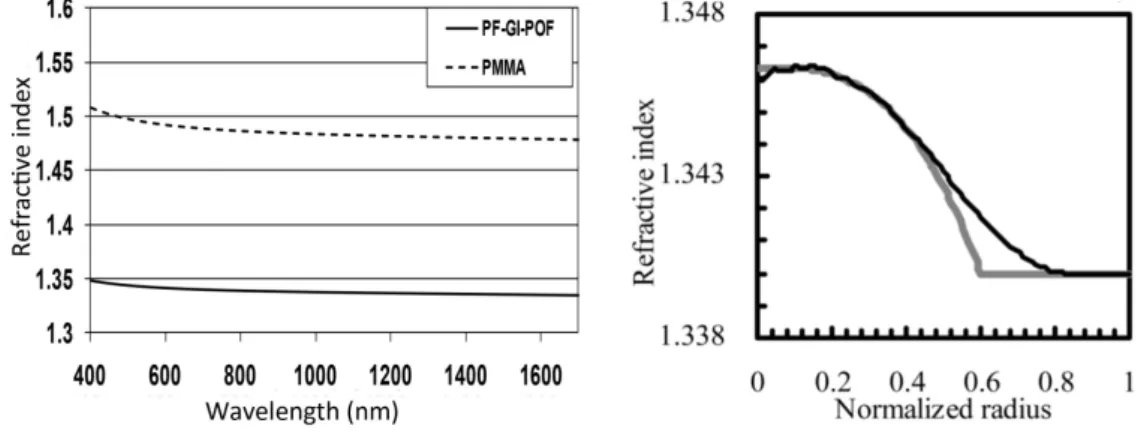
II Perfluorinated graded index polymer optical fiber . . . 75
II.1 Fabrication and physical properties . . . 75
II.2 Theoretical transmission model of the PF-GI-POF . . . 78
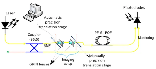
II.3 PF-GI-POF characterization . . . 80
II.4 Temporal transmission characterization of the PF-GI-POF . . 81
II.4.1 Modeling and simulation of the PF-GI-POF . . . 81
II.4.2 PF-GI-POF loss measurement . . . 85
II.4.3 Frequency response measurement . . . 90
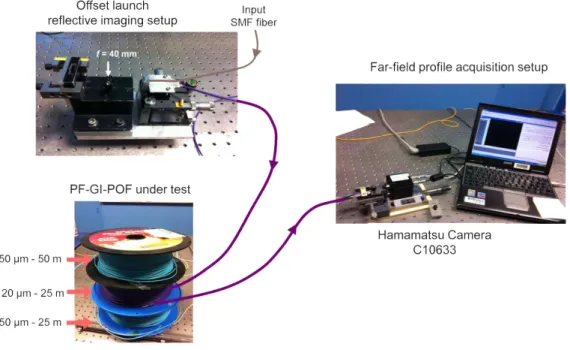
II.5 Far-Field transmission characterization of the PF-GI-POF . . 91
II.5.1 One-dimensional Far-Field profile . . . 92
II.5.2 Two-dimensional Far-Field measurement . . . 92
II.5.3 Far-field speckle modelling . . . 96
III Single-mode fiber for home networks . . . 97
III.1 Physical characteristics . . . 97
III.2 Spatial characterization of the G657 far-field profile . . . 97
IV Conclusion . . . 99
Bibliography . . . 102
Figures and tables . . . 103
4 Optical free-space cell dimensioning 105 Introduction . . . 107
I Optical access point . . . 107
I.1 Diffractive optical element . . . 107
I.2 Optical beam free-space profile . . . 110
II Wireless receiver . . . 112
II.1 Optical filter . . . 112
II.2 Optical concentrator . . . 113
II.2.2 CPC gain measurement . . . 116
II.3 Pre-amplified photodiode . . . 118
II.3.1 Photodiode characteristics . . . 118
II.3.2 Preamplifier characteristics . . . 120
II.4 Receiver noises . . . 121
II.4.1 Different receiver noise types . . . 122
II.4.2 Ambient noise . . . 123
II.4.3 Conclusion . . . 124
III NLOS free-space link performance . . . 124
III.1 Modulation scheme . . . 124
III.1.1 Transmission techniques . . . 125
III.1.2 On-Off Keying modulation . . . 127
III.2 Signal-to-noise ratio and receiver sensitivity . . . 130
III.3 Dimensioning of the NLOS link . . . 133
IV Software modelling and simulation of the free-space link . . . 137
V Conclusion . . . 139
Bibliography . . . 141
Figures and tables . . . 142
5 Optical downlink performance: simulation and experimental re-sults 145 Introduction . . . 146
I Downlink transmission software simulation . . . 146
II Experimental test of the downlink . . . 148
III Conclusion . . . 156
Bibliography . . . 157
Figures and tables . . . 158
Conclusions 161 6 Résumé détaillé 167 I Sujet, problématique et état de l’art . . . 168
II Méthodologie . . . 169
III Architecture proposée . . . 169
IV Validation du budget optique . . . 170
V Caractérisation de la fibre pour la distribution des cellules optiques en espace libre . . . 171
VI Caractérisation de la cellule optique en espace libre . . . 174
VI.1 Point d’accès optique . . . 174
VI.2 Dimensionnement de la cellule optique en espace libre . . . 174
VII Simulation et test expérimental du système global . . . 175
VII.1 Simulation du lien descendant . . . 175
VII.2 Test experimental du lien descendant . . . 177
VIII Conclusion . . . 178 List of Publications 181
A Definitions of some radiometry elements 185 B Beam shaping at the Optical Access Point 187
General Introduction
Wireless communications has shown its prodigy in the telecommunications domain. The fast development of wireless personal communications technologies in terms of devices, provided bit rate, services and applications has created a new society where most people want to be connected anywhere and anytime, accustomed to the com-fortability of wireless access. Nowadays, mobile communications are offered by a large variety of radio frequency technologies, a generic term gathering several com-plementary access technologies.
In the last few years, the required bit rates for new services and applications began to exceed the bandwidth limits of radio frequency channels. Until recently, users were satisfied with the wireless services in outdoor environment which, despite a limited bit rate, have brought enough capacity to develop new applications such as video call, internet browsing, or TV watching at moderate bit rate.
In an indoor environment, see figure 1, the bit rate provided by wireless technologies (WiFi) is limited, and users suffer from waiting during the downloading of large files, sometimes exceeding the Gbit in size.
In this framework, most network operators and service providers are investigating alternative techniques to provide wireless high bit rate channels in an indoor environ-ment. Optical technologies are used on a large scale with optical fiber infrastructure now spread out from core to access network, as shown in figure 2. The present fiber-to-the-home massive deployment in most developed countries is a major step towards a high-speed internet access network. The next phase will be the extension of the high-speed optical technologies within home and buildings to provide end-to-end broadband networks. National or international research projects such as Alpha [2], Techim@ges [3] or Omega [1] have investigated the topic in order to provide Gbps bit rate demonstrators in indoor environment.
Figure 2: Network architecture from core to access network. Optical fiber links now extend over 98 % of the coverage, from the access to the WAN networks.
Another topic of interest is the ever increasing energy consumption in telecom-munications networks. From a study performed by Deutsche Telekom in 2008, it was shown that the average daily energy consumption dedicated to communication technologies per household is about 2.5 KWh. The extrapolation to the whole pop-ulation of Germany leads to a national estimated daily energy consumption of 100 GWh, only dedicated to the multimedia use. Surprisingly, this represents half of the production of a large nuclear plant. Concerning public health issues, many studies have investigated the effects of electromagnetic radiation, taking the radio frequency networks dimensions into account [4]. Despite many warnings from both biologists and customer associations, no precise harmful effect have been stressed, but wire-less network deployments now tend to minimize the radio frequency "electrosmog" within densely populated areas.
As an alternative to radio frequency, wireless links can also be performed with light-waves propagating in free-space. For outdoor applications, the solution is referred to as "free-space optics" or FSO, while the "optical wireless" term or OW, is custom-ary for indoor communications. Optical wireless communications offer attractive features, like the potential for very high data rates (more than 10 Gbps) owing to a huge bandwidth which is still available and unregulated, unlike the radio frequency spectrum, which is getting increasingly crowded. Moreover, Optical wireless does not produce any electromagnetic interference with systems operating in the radio fre-quency spectrum. Optical wireless can be classified as a function of the transmission wavelength. Two options are usually considered as the most attractive due to the availability of low-cost components (850 nm window) and robustness with respect to eye-safety (1550 nm window). Lately, there has been an increasing interest in developing visible light communications, where light emitting diodes primarily ded-icated to lighting or signalling purposes have also been used to transmit high-speed digital information. Finally, most integrated optical components are characterized by a lower energy consumption as compared to radio frequency devices in addition to the reduction in the number of electro/optic conversions.
These points motivated us to study all-optical indoor high-speed wireless commu-nications networks with potential reduced environmental and health impact. The proposed system aims at distributing optical wireless cells in different rooms of a home interconnect by optical fiber to a base station inside the home.
This thesis consists of five chapters, whose contents are briefly explained below. Chapter 1 is dedicated to the state of the art of indoor communication sys-tems. Access network and new end-users applications and services are introduced. Moreover, wired communications and the different radio frequency and microwave wireless technologies are presented. Finally, optical wireless communications and their advantages are tackled.
The design and the description of the proposed optical free-space cell system is the subject of chapter 2. System constraints, wavelength choice and different com-ponents used are introduced in this chapter.
Chapter 3 is dedicated to the fibered part of the proposed system, showing the study of the fiber that can be used in this application. A theoretical study, some simulation and experimental work are performed to characterize the fiber link and to assess the suitable fiber type for the studied architecture.
In chapter 4, the optical free-space cell is characterized. Using a theoretical mod-elling and a software simulation, the optical access point and the mobile receiver are thoroughly studied and their building modules are characterized. Furthermore, dif-ferent noise sources at the receiver stage are evaluated in order to demonstrate the dominant noise, which enables us to study the performance of the narrow line-of-sight (NLOS) link in order to estimate the signal-to-noise ratio, and then to define
the limits of the free-space cell.
In the last chapter, we characterize the performance of the global downlink. Firstly, a simulation of the global system is performed based on the combination of the simulation presented in chapter 3 and 4. Furthermore, an experimental bench of the downlink is built. The eye diagram is displayed and the signal-to-noise ratio is measured to validate the feasibility of the proposed system.
The document is concluded by a summary of the main results and some perspec-tives of the future work.
This work was supported by a grant from Institut Mines-Telecom, in the frame-work of the Futur et Ruptures program.
Bibliography
[1] projet FP7-ICT (2008-10) OMEGA: Home Gigabit Access. www.ict-omega.eu. [2] ALPHA: Architectures for fLexible Photonic Home and projet FP7-ICT
(2008-10) Access networks. wwww.ict-alpha.eu.
[3] Techim@ges project. http://www.images-et-reseaux.com/fr/les-projets/. [4] C. Grangeat, C. Person, D. Picard, and J. Wiart. Measurement of the Specific Absorption Rate (SAR) on mobile phone - COMOBIO Project contribution to international standards. Annals of telecommunications, 58(5-6):1509–1511, May-Jun. 2003.
Chapter 1
Indoor network communications
Contents
Introduction . . . 23 I Communications in the access network . . . 23 I.1 Evolution of communications in the access network . . . 23 I.2 End-user new and future services in in-building networks 24 II Wired communications for indoor networks . . . 26 II.1 Coaxial cable . . . 26 II.2 Optical fiber communications . . . 27 II.3 Power line communications . . . 28 II.4 Conclusion . . . 29 III Wireless communications using radio and microwave frequencies 29 III.1 Bluetooth . . . 29 III.2 WiFi . . . 30 III.3 Ultra wide band . . . 31 III.4 60 GHz wireless communications . . . 32 III.5 Radio-over-fiber . . . 33 III.6 Conclusion . . . 34 IV Optical wireless communications . . . 35 IV.1 Outdoor optical wireless communications . . . 37 IV.2 Indoor optical wireless communications . . . 39 IV.2.1 Visible light communications . . . 39 IV.2.2 Infrared optical wireless communications . . . 40 V Advantages of optical wireless communications . . . 42 VI Conclusion . . . 43 VII Objectives and outlines of the PhD thesis . . . 44 Bibliography . . . 50
Introduction
In the past few years, an unprecedented raising of number of laptop computers, per-sonal digital assistants (PDAs) and other mobile terminals has been observed. This evolution was accompanied by a huge demand for wireless data transmission, in the purpose of avoiding wires and connectors to supply some kind of mobility, especially, in cases where the distance between the transmitter and receiver is relatively small e.g. at airports, rail stations, offices or homes.
To date, wireless communications are mainly provided by radio frequency (RF) com-munications using WiFi channels, a widespread technology offering a maximum bit rate of 300 Mbps according to the 802.11n standard. But, new bandwidth-hungry services are used today, such as high definition (HD) video and 3D video, and such future applications as ultra high definition video, Web 3D and robotic assistant will require a higher bit rate, that will exceed the Gbps in the indoor network framework. These applications start to be realistic, mainly after providing this high bit rate in the access network, with the installation of the fiber to the home (FTTH).
These services and applications, that will be described later, give us a view of the future indoor network with the required high data rates (few hundred of Mbps to several Gbps). This network will support multiple services with widely varying characteristics and requirements having a better Quality-of-service (QoS) and less energy consumption.
In this chapter, a short history of the communications evolution will be presented. The most common technologies for wired and wireless communications having ra-dio frequency and optical carriers in indoor environment will be shortly explained. Then, we will present the advantages of optical wireless communications, the new services in in-buildings networks and the required bit rate before concluding the chapter with the objectives and outline of this thesis.
I
Communications in the access network
I.1
Evolution of communications in the access network
The communications evolution started in the 1790s with the french engineer Claude Chappe, who invented the optical telegraph. The system was based on a set of semaphores mounted on towers exchanging messages from one tower to the next one, in direct view. After 1845, the electrical telegraph appeared progressively replaced the optical telegraph. The next step was the telephone introduced in 1848. The first transfer of data called "computer networking" appeared in 1969, and a global system of interconnected computer networks was presented in 1983 under the name of "internet". Regarding mobile communications, the first generation (1G) of wireless telephone technology was introduced in 1980s. This first analog generation was replaced by the second generation (2G) of digital networks which was followed by the 3rd generation (3G) in the late 1990s, finding applications in wireless voice telephony, mobile internet access, fixed wireless internet access, video calls and mobile TV. A progression of this generation leads to 3.5G and 3.75G
providing mobile broadband access of several Mbps to smartphones and mobile modems in laptop and computers. Nowadays, the new generation is being installed around the world through the long term evolution (LTE) marketed as 4G, which can provide a maximum downlink bit rate of 300 Mbps and a peak uplink of 75 Mbps. The different generations of this standard are mainly designed for smartphones and full mobility communications. Another area of wireless communications that has progressed in the late decade is the local area network (LAN) and the most spread technology used for that is the WiFi, where the mobility is full in a limited area around the access point. This technology is presented in a section below. On the other hand, wired communications in the access network were largely developed with the introduction of optical fiber yielding the development of FTTH networks to achieve potential Gbps bit rates, as benefits of the huge bandwidth of the optical fiber.
I.2
End-user new and future services in in-building networks
High speed indoor wireless systems are nowadays subject of a large number of na-tional and internana-tional research projects such as Omega [1], Alpha [2] which are parts of the seventh framework programme FP7 or Techim@ges [3] of "Pôle Images et Réseaux". These projects had the goal to provide a higher bit rate in compar-ison to the existing systems for the future applications and services, depending on different parameters such as bit rate, maximum latency tolerance, delay variations, mobility traffic priority and security. In this paragraph and based on these two stud-ies, we shortly present some new and future services, their specific characteristics and their required bit rates.
• Video on Demand (VoD) and Multimedia content production and delivery: VoD uses Real Time Streaming Protocol (RTSP) to stream video to the end-user based on Internet Protocol-based television (IPTV). High quality video files having a size as large as 10 Gbit should be downloaded to the local server in the shortest possible time (< 1 min) to permit the user to play it locally. A speed of 1 Gbps will be required to download quickly the video file and to satisfy users.
• Video streaming: It is referred to direct streaming of uncompressed video from media server or player (DVD, blu-ray disk) to one or several media renderers (TV set for instance) without downloading video before. The data rate of this transmission goes from several Mbps (VGA format or 640×480p @ 59.94/60 Hz) to 10.2 Gbps (in the case of Full HD TV or 1920×1080 @ 59.94/60 Hz with 48 bit "Deep color").
• Immersive TV : The size limits of TV screens prevent an immersive experience with conventional TV or HDTV systems. A solution to overcome this size limit is to use a projector, but in this case, the number of pixels per inch is reduced limiting the image resolution. An immersive home TV can be provided using the technique proposed by Nippon Hoso Kyokai (NHK - Japan
Broadcasting Corporation) based on the use of classical flat screen instead of the dome for the projection introducing the Ultra HDTV [4] with a screen resolution of 7680×4320 pixels, 16 times bigger than standard HDTV with bit rate of the uncompressed images of 24 Gbps. In 2006, NHK developed a codec to compress audio part of video signal in order to squeeze 24 Gbps into 600 Mbps [5].
• Free view-point TV : Free view point (FVP) is a TV service which allows the final user to freely chose the point of view of the show. A similar service is provided today by some broadcasters but limited to views, of different using cameras for broadcasting, while, the free view-point should permit the user any possible viewpoint not necessarily corresponding to a physical camera. An example of this service is presented on [6] where 15 cameras, each one, broadcasting an 1080p stream are used and the maximum required bit rate is 15 × 62.5 = 937.5 Mbps.
• Stereoscopic TV : It represents different manners to recreate 3D images repre-sentation in the goal of transmitting to the end-user the correspondent feeling of depth with images not only on screen plane, but also behind and ahead the screen. This application requires a bit rate of 320 Mbps.
• Web 3D: The next expected major application in the internet will be the web 3D, especially with the recent development of 3D films and Video, the spread of 3D screens, 3D cameras and applications on 3D. Web 3D can offer an immersive experience which will attract a large user number as compared to the static graphical interface in today’s Web. In the last years, a web 3D consortium was founded to create and deploy open standards that enable the communication of the real-time 3D across applications, networks and XML web services [7]. The required bit rate for this application is up to 1 Gbps. • Remote Residential Backup: Today, end-users produce large amount of data,
due to extensive use high resolution digital cameras and video equipments on mobile terminals. This data are shared between families and friends, but they need to be stored on local computer or media server, with storage spaces of more than 1 Terabyte [8]. The remote file backup is a service of increasing popularity, which requires an average capacity of 1 Gbps on about 2 hours to transfer the Terabyte. This duration gives the possibility to perform the backup during the time when the network is not congested (between 12 am and 4 am in business areas and between 10 am and 4 pm in residential areas). • Grid computing: It is a grid of computer resources from multiple adminis-trative domains (computing, storage,..) working together to solve a common problem, as, for example the online visualization of a virtual environment [9]. This application requires a bit rate exceeding the Gbps.
The services presented above and their required bit rates are summarized in table 1.1. Some of these services are ready for deployment and the others are expected
Table 1.1: New and future services and the required bit rates Services bit rate (Mbps) Remarks Stereoscopic TV 320 Future (1080p) Remote Residential Backup 500 No packet loss
Immersive TV (UHDTV) 600 Compressed for broadcast 4230p Free view point TV 937 Future (1080p)
Video on Demand up to 1000 Compressed using MPEG-2 or MPEG-4 Web 3D 1000 Future
Grid computing 1000 Minimize energy consumption Video streaming 1000 to 10000 Uncompressed
Immersive TV (UHDTV) 24000 Uncompressed 4320p to be deployed for a large number of end-users. In addition to the high bit rate required, these applications should be provided for laptop and other mobile termi-nals which, induce operators and broadcasters to offer the high bit rate with some mobility degree.
In this context, users in indoor environment should have access to high-speed net-works through a wired and wireless netnet-works. Today, most end-users use two trans-mission channels to be connected all the time and change between these two chan-nels, depending on their position and the required bit rate. Wired communications are used generally on a fixed place while wireless is used for mobile users but of-fering a smaller bit rate. In the next sections, different wired and wireless indoor communication technologies are described, showing their respective advantages and limits.
II
Wired communications for indoor networks
In this section, we present a brief description of wired communications used in indoor environment, explaining the differences between them, and the limits of each channel in terms of bit rate and distance link.
II.1
Coaxial cable
The coaxial cable is a transmission line for radio frequency signals invented by the British engineer Oliver Heaviside in 1880 [10]. Today, it is the most commonly used cable in indoor networks to connect radio transmitters and receivers, computer net-works, and distributing cable television signals. This cable was also used to transmit Ethernet standards, a family of computer networking technologies introduced in the 1980s as IEEE 802.3 [11] for local area networks. This cable is able to transmit a bit rate from 3 Mbps to more than 10 Gbps, over a distance up to 100 m [11].
II.2
Optical fiber communications
The first serious proposal to employ optical fibers as a medium for telecommuni-cations transmission dates back to 1966 by the Chinese engineer K. C. Kao and the Britsh engineer G. A. Hockham. At that time, the problem was the high at-tenuation of the existing fiber which was about 1000 dB/km. The low bandwidth and the fragility were also an important issue. The progress of the fiber proper-ties started to be rapid after 1970, when the United States company Corning Glass Works achieved a fiber with a loss less than 20 dB/km. Nowadays, the standard single-mode fiber (SMF) has a very low attenuation of 0.2 dB/km at 1.55 µm. The fiber progress was not limited to the attenuation, but to all other fiber parame-ters, making it able to be the support of high bit rate links over some hundred of kilometers. The fiber evolution was accompanied by the advancement of opto-electronic devices such as transmitters (light emitting diodes (LEDs), laser diodes (LDs)) and receivers (p-intrinsic-n (PIN) photodiodes and avalanche photodiodes (APDs)). In 1990, optical fiber communications system operating at a bit rate up to 2.5 Gbps were commercialized with a repeater spacing of about 60-70 km [12]. Earlier, the erbium-doped fiber amplifiers (EDFA), which can produce an optical gain higher than 20 dB over a large bandwidth (1525 - 1565 nm), contributed to a high progress in digital photonics transmission [13]. Shortly after, lightwave sys-tems moved to wavelength division multiplexing (WDM), benefiting from the EDFA and then, dense WDM (DWDM) optical amplified transmission system were able to transmit multiple 10 Gbps channels. Nowadays, optical transmission systems provide a capacity of several Tbps [12]. This evolution led to a huge deployment of the fiber optic in the core, metropolitan and access network. FTTH is the last emerging technology of the optical fiber, which is currently being installed. Fibers for home networks demand some special characteristics mainly in terms of bending and fragility, which has motivated researchers to develop fibers with the required characteristics. In this frame, the perfuorinated graded index polymer optical fiber (PF-GI-POF) is a new model of polymer fiber with a large bandwidth, allowing the transmission of 40 Gbps over 100 m [14].
(a) (b)
Figure 1.1: (a) Plastic optical fiber samples for home networks and (b) connector for plastic optical fiber (sc standard)
systems can now be used and connected to terminals offering a bit rate of several Gbps. Although the fiber for home network evolves, the risk of fiber break after the installation by users is still high, in addition to the congestion problem of coaxial cables in indoor environment.
II.3
Power line communications
Power line communications (PLC) is a wired technology for indoor network with low energy consumption. Originally, the electrical network was used for energy trans-portation. The electrical network combines the high voltage (HV), medium voltage (MV) and low voltage (LV) power line transmissions. Each of them can be used to transmit data and information in outdoor or access networks. The PLC access technology is depicted in figure 1.2 [15].
Figure 1.2: Power line communications network deployment scheme [15] The indoor network can also be implemented using PLCs using the LV private instal-lations and present cost-effective communication network. The idea is to transmit high-frequency signals through the same cable network used for transmitting the electricity power to household users. The combination between the current and the data should be done by a device in the local transformer stations. A modulated carrier signal is impressed on the electrical wiring system. The advantages of this technology is the possibility to use the existing electrical infrastructure to provide an access broadband with a high potential coverage by a simple and fast in-house
installation. At the beginning, indoor PLCs were focused on services related to con-trol of electrical equipments, which require a relatively low bit rate with no real-time performance. These services can be operated easily in narrow-band PLC within the frequency range of 9-140 KHz, offering a data rate of some thousands bits per second [16]. The increasing use of internet and applications at high bit rates has encouraged the development of a broadband PLC requiring bandwidths up to 100 MHz [17]. In laboratory trials, PLC systems can offer transmission bit rates up to 500 Mbps in local area networks applications [18], and some commercial products reach 200 Mbps at the physical layer.
II.4
Conclusion
Indoor wired communications were developed over the last decades to provide the high bit rate to the customers through different technologies. This evolution was ac-companied by the diffusion of wireless communications systems giving the possibility to remain connected using a mobile terminal, anywhere inside a home. In the next section, the different wireless indoor communications technologies are presented and their advantages and limits are explained.
III
Wireless communications using radio and
mi-crowave frequencies
Wireless communication links were implemented over the years by different radio frequency technologies ranging from 535 KHz to LAN network channels at 2.4 GHz. Considering microwave signals, this range extends to 300 GHz, where the wavelength of the wave is 1 mm. The wireless communications based on RF technologies for indoor area are listed in the sections below.
III.1
Bluetooth
Bluetooth is a wireless technology using a RF wavelength range designed for short distance communications to replace cables for printers, joysticks, keyboards or mice. It can be used also to interconnect portable computers or mobile phones. Bluetooth is an idea proposed by Ericsson Mobile communications, which started in 1994 to present a low power system to replace the cables used on its mobile phones and corresponding accessories. Ericsson formed with Nokia, IBM, Toshiba, and Intel the Bluetooth Special Interest Group which released in the next year the first Bluetooth protocol. 3COM, Agere (Lucent Technologies), Microsoft and Motorola joined this group in 2000 showing the high interest for this technology.
Bluetooth is an omnidirectional technology which does not require a direct view between the transmitter and the receiver. In most countries, Bluetooth devices use the band between 2.402 GHz and 2.4835 GHz, representing 79 1-MHz-wide channels. The channels are accessed using the Frequency-Hopping Spread Spectrum multiplexing technique offering a theoretical bit rate of 1 Mbps (≈ 700 Kbps in
reality), using Gaussian shaped frequency shift Keying (GFSK) modulation. This modulation is a type of frequency shift keying modulation (FSK) which uses a Gaussian filter to shape the pulses before they are modulated in the goal of reducing the spectral bandwidth and out-of-band spectrum, to meet adjacent-channel power rejection requirements [19]. The new version of the Bluetooth standard is based on ultra-wide band and provides a maximum bit rate of 24 Mbps. The link distance can reach 100 m, depending on the emitted power [20].
As a conclusion, Bluetooth offers a relatively large covered area (100 m) with low consumption, but with a limited bit rate. The parameters of a typical Bluetooth link are summarized in table 1.2.
Table 1.2: Main characteristics of the Bluetooth technology [20] Parameters Min Max Units
bit rate - 24 Mbps Link distance 10 100 m Carrier frequency 2.402 2.483 GHz Number of users 2 8 Power consumption 20 100 mW
III.2
WiFi
The WiFi (or "Wireless Fidelity") is a RF technology respecting the IEEE 802.11 standard, basically providing a bit rate of 1 or 2 Mbps over some tens of meter. This standard used the spectrum ranging from 2.4 GHz to 5 GHz. This technology attracted a high number of customers encouraging the companies and researchers to increase this technology performance, resulting in the IEEE 802.11b standard (11 Mbps), and the 802.11a offering a bit rate of 54 Mbps [21]. The evolution of this standard was not limited to increasing the bit rate but also included the evolution of security and quality of service. There are no fixed link distance for WiFi, depend-ing on the environment where the signal propagates, such as builddepend-ings, and other elements that can attenuate the signal. Figure 1.3 presents the general components of a WiFi network showing different access point on a basic service set (BSS) and the connexion between two BSS through a distribution system. It presents also an Ethernet connexion to servers or disks. The covered area of WiFi is limited on a zone of a diameter of several tens of meters around an access point and the bit rate is divided between the number of terminals connected to the same access point. The advantages of this technology are the ease and rapidity of installation, the full mobility in covered area, the unecessity of direct view. This technology suffers from some problems such as the need of high securing, the sharing of bandwidth between users and the limited bit rate. The last evolution of this technology is given by the 802.11n standard offering the possibility of more than 300 Mbps over a distance from 20 to 50 m in indoor environment around the access point, and 300 m in outdoor environment with the decrease in bit rate when the distance from the access point
increases [21].
Figure 1.3: General components of a WiFi network (network view)
III.3
Ultra wide band
The Ultra Wide Band (UWB) is a recent type of RF communications technology based on the transmission of short pulses with relatively low power spectral density (PSD). UWB technology gives the possibility to provide a high bit rate exceeding a Gbps wireless personal area networks (WPAN) over a relatively short distance (10 m) [22]. UWB uses an unlicensed wide band of RF spectrum defined by the Federal Communications Commission (FCC) in the range from 3.1 GHz to 10.6 GHz for indoor communications and from 22 to 29 GHz for vehicular radar applications [23], where each radio channel can have a bandwidth exceeding 500 MHz, depending on its center frequency. The FCC fixed the maximum radiated PSD to −41.3 dBm/MHz in both cases to minimise interference between wireless services (licensed or un-licensed) [24]. The low power consumption motivated the use of UWB for radar systems, but it is used on many others applications such as:
• Wireless personal area networks: The UWB technology can be used to provide a high bit rate of several hundred Mbps within a short-range of 10-20 m with low cost and high power efficiency.
• Sensor networks: In this context, a large number of nodes is distributed in a defined geographical area. This network can be used for monitoring, pollution tracking, equipped on soldiers or military robots and emergency response sit-uations. For that, UWB can be used in additional services e.g. underground,
through-wall, ocean imaging, medical diagnostics and border surveillance de-vices [25].
• Vehicular radar systems: UWB can be used for target differentiation, in-telligent collision-avoidance. Airbag deployment, and adaption of suspen-sion/breaking, depending on road conditions can be improved by using this technology. It is sometimes integrated into vehicular entertainment and navi-gation systems.
This technology is poorly developed for indoor environment and the commercialised devices are very limited.
III.4
60 GHz wireless communications
The 60 GHz technology provides an attractive bandwidth for high bit rate commu-nications offering the possibility of Gbps, standardized by the IEEE 802.15.3c.
Figure 1.4: Worldwide band allocation for 60 GHz technology
As free-space attenuation of radio signals increases when the carrier frequency in-creases, 60 GHz technology is suitable for high bit rate communications over short distance line-of-sight (LOS) links.
In 2004, Applied Millimeter Wave Laboratory of Motorola Labs demonstrated a 3.5 Gbps link over 3 m [26], and in 2006, IBM T. J. Watson Research center shown a 630 Mbps link over 10 m [27]. Tomkins et al. from University of Toronto achieved in 2009 the demonstration of a transmission of data rates exceeding 6 Gbps of up to 2 m [28].
Figure 1.5 presents the architecture of a transmitter and a receiver designed Chalmers University and fabricated on 0.15 µm AsGa pHEMT [29]. The transmitter contains a 3-stages power amplifier, a mixer and a local oscillator. The receiver is composed of low noise 3-stages amplifiers and an image rejecting mixer and a local oscilla-tor (×8). This technology is not yet commercialized and suffers from a very high attenuation due to the oxygen absorption band in the air.
Figure 1.5: 60 GHz transmitter and receiver architectures [29]
III.5
Radio-over-fiber
Radio-over-Fiber (RoF), as its name suggests, is a technology that uses the optical fiber to transmit RF signals. In free-space, the loss of an RF signal due to reflection and absorption increases with frequency, as for transmission lines. Therefore, the transmission of high frequency RF signals electrically or in free-space over a long distances is problematic and costly due to the necessity of regenerating equipments. The idea of RoF is to transmit the RF signals over an optical fiber as long as pos-sible to benefit from the very low attenuation of optical fiber (0.2 dB/km at 1550 nm), and then to diffuse the RF signal over small distances, offering a high bit rate wireless solution. The RoF is also used to transmit existing RF technologies in order to increase the signal range of WiFi, UWB [30] and 60 GHz over fiber [31].
Figure 1.6: IM-DD Radio-over-Fiber scheme
Figure 1.6 presents the block diagram of a RoF channel using a circulator and one antenna to diffuse the RF signal for the downlink and to detect the RF signal for the uplink. This method uses Intensity Modulation with Direct Detection (IM-DD) which is the simplest form of the RoF link. For the downlink, at the central sta-tion, the RF signal directly modulates the laser diode and the resulting signal is
transmitted to the remote antenna unit (RAU) over the optical fiber. At the RAU, the transmitted RF signal is detected by the photodetector (PIN in general) and recovered by direct detection to be amplified and radiated by the antenna, and transmitted to the mobile unit (MU). The up-link RF signal generated by the MU is detected by the RAU. This signal is used to directly modulate the laser present at the RAU, then, transmitted over the optical fiber, and detected by the photodiode (also PIN in general) at the central site. The RoF based on IM-DD modulation is perfectly linear when the transmission is performed without chromatic and modal dispersion and in this case, the optical signal is transparent relatively to the RF signal. This modulation method can be used for indoor RoF where the fiber link is about some tens of meter (no chromatic and modal dispersion).
Figure 1.7: Radio-over-Fiber pico cellular architecture [32]
Figure 1.7 shows an example of RoF distributed picocells in in-building network, where a high number of user devices needs to be supported. The system presented on this figure is conceived to provide a high bit rate of 1 Gbps by using 60 GHz radio links.
The RoF technology is a way to increase the bit rate and to reduce power consump-tion due to the fiber transparency compared to the wireless transmitted signal over wall and other obstacle causing a high attenuation of the signal and then, the ne-cessity to emit high power at the access point. The need to use of laser and antenna at the two extremities of the RoF link makes this type of link not very easy to use and increases the system price.
III.6
Conclusion
Today, such RF technologies as WiFi and Bluetooth are hugely deployed around the world. These technologies are however limited in terms of bit rate (some tens of Mbps). Otherwise, another RF technologies were developed to provide the higher bit
rates required by new services and applications. These technologies presents also bit rate limitations to some hundred of Mbps and reveals sometimes very complex and expensive. Different RF technologies, their maximum bit rate and covered distance are summarized in table 1.3. An all-optical solution could be an alternative to increase the bit rate by eliminating the distribution of antennas at the fiber output. Different optical wireless communications technologies will now be presented in the next section.
Table 1.3: Summary of different RF technologies and their characteristics Technology bit rate (Mbps) Link distance (m)
Bluetooth 24 100 WiFi 54 100
UWB 300 20
60 GHz 630 10
IV
Optical wireless communications
In parallel to the massive deployment of fiber optical communications in core, metropolitan and access networks connecting continents and providing bit rates that may exceed the Tbps, an alternative optical communication technology started about 30 years ago. It proposed to supply high bit rates in a part of the network where the installation of optical fiber is very difficult and expensive [33]. The concept is simple and similar to fiber communications with the difference that the transmis-sion medium is free-space. The direction of the optical beam and its directivity can be defined relatively to the application and it can be determined by such simple op-tical components as lenses or prisms. Opop-tical free-space links are strictly limited by the eye safety standards (and skin safety) defining the maximum permissible emitted power that does not have any harmful effects to the users. Optical wireless com-munication is a multidisciplinary domain of study including a wide range of areas: optical design, optoelectronics, electronics design, channel modelling, communica-tion and informacommunica-tion theory, modulacommunica-tion, wireless optical network architectures and many others. The type of optical free-space transmission is defined as a function of the beam divergence, classifying the link in three different topologies, as detailed in the next paragraphs.
Line-of-Sight links The line-of-sight (LOS) or point-to-point is the link with the quasi-alignment between the transmitter and the receiver. The low divergence beam and narrow field-of-view (FOV) detectors permit the rejection of high percentage of noise from ambient light. This type of link with narrow divergence does not provide a large coverage. However, a smaller attenuation is achieved compared to other topologies with higher divergence, and, the link distance can be longer. Whereas the total alignment to the optical signal is not possible but also in order to offer
some flexibility to the link, this free-space geometry includes very small divergence topologies (< 3◦), referred to as narrow LOS (NLOS), as depicted in figure 1.8.
Figure 1.8: NLOS topology
This topology requires a direct view between the transmitter and receiver which reduces the flexibility of the link and makes it very sensitive to any obstacle. In this configuration, the signal does not suffer from multi-path distortion, hence no inter symbol interference (ISI), which makes the link bit rate only dependent from the power budget.
In a LOS link, the bit rate can be increased by spatial division multiplexing tech-niques. The mobility degree can be also increased by multiplying the number of LOS links or by tracking systems that achieve 155 Mbps over a distance of nearly 2 m in an indoor environment [34]. Although most LOS links use a single transmitter and receiver, a higher gain can be achieved by using multiple transmitters and re-ceivers. The implementation of a Multiple-Input-Multiple-Output (MIMO) system requires the use of laser and photodiode arrays [35], or a spatial light modulator as a transmitter and an imager as a receiver. The MIMO LOS link is used in many appli-cations such as 2D barcodes [36], page-oriented recording [37], holographic storage [38] and MIMO optical communications link [39].
Wide Line-of-Sight links The wide line-of-sight (WLOS) is characterized by a transmitter with a larger divergence angle as compared to the LOS. The receiver used also has a larger FOV. Figure 1.9 shows a WLOS topology scheme. The link geometry does not require the alignment between the transmitter and the receiver contrary to the direct view between them which is essential. The WLOS is char-acterized by a higher attenuation as compared to LOS or NLOS making the link distance smaller. The wide beam transmitter in this topology may cause multi-path due to reflexions from the wall and objects in the room, thus generating ISI and affecting the bit rate and the quality of the signal.
sys-Figure 1.9: WLOS topology
tem contains an access point with a transmitter and multiple mobile receiver in covered zone [40].
Diffuse indoor optical links A diffuse indoor optical link is depicted in figure 1.10. In this configuration, an optical transmitter diffuses the optical signal in all possibles directions. The signal at the receiver is the optical power collected by the photodiode coming from the transmitter directly or after many reflexions. This type of link does not need a direct view between the transmitter and the receiver. This link type is generally studied for indoor environment. A wide beam transmitter and a large FOV receiver is used to detect reflections of the diffused signal inside the room and to establish the communication link [39]. The received signal suffers from a multi-path dispersion caused by the large number of reflected rays at the receiver entrance area. As a result, a high ISI which reduces the maximum bit rate.
The first diffuse infrared system was proposed by Gfeller and Bapst, providing a bit rate of 1 Mbps at 950 nm wavelength [41]. The fastest totally diffuse system is reported by Marsh and Kahn [42] offering a bit rate of 50 Mbps, using a 805 nm wavelength optical carrier.
After presenting different free-space link geometries, we now propose an overview of optical wireless communications studied in outdoor and indoor environments.
IV.1
Outdoor optical wireless communications
A large part of optical wireless communications consists of the outdoor systems known under free-space optic (FSO) links. This represents a complementary solu-tion to the optical fiber local area network and broadband access network providing a "last-mile" high bit rate at low cost where the optical fiber installation is
con-Figure 1.10: Diffuse link topology
sidered to be complicated [33]. Currently, a commercial FSO system working at 10 Gbps offers the possibility to connect some buildings in a city at distance of some km or some sites of university or company [43]. Figure 1.11 presents an example of FSO link and some impairments that may occur during the transmission.
Figure 1.11: FSO transmission systems [44]
The FSO is a fixed point-to-point optical infrared transmission system which mini-mizes the probability to establish link, to localize it, to intercept it and detect the signal, contrary to the RF transmission. This characteristics make the FSO com-munication very suitable for high security military comcom-munications.
Obscuration (fog, clouds, snow, ...) along the link causes a multiplicative intensity noise which is known as scintillation, which reduces the received power and, then, the link distance. The attenuation of this type of link is not considered a major problem, especially for the used distance link (1-10 km). This consideration is reen-forced by the fact that the system does not require to respect the standard for eye safety due to the absence of people on the link trajectory, given the possibility to


![Figure 2.9: Spectral power densities of the three dominant sources of indoor back- back-ground illumination [9]](https://thumb-eu.123doks.com/thumbv2/123doknet/8266704.278351/67.892.137.714.162.570/figure-spectral-densities-dominant-sources-indoor-ground-illumination.webp)