Science Arts & Métiers (SAM)
is an open access repository that collects the work of Arts et Métiers Institute of Technology researchers and makes it freely available over the web where possible.
This is an author-deposited version published in: https://sam.ensam.eu
Handle ID: .http://hdl.handle.net/10985/8496
To cite this version :
José OUTEIRO, Antonio BATISTA, M.J. MARQUES - Residual Stresses Induced by Dry and Cryogenic Cooling during Machining of AZ31B Magnesium Alloy Advanced Materials Research -Vol. 996, p.658-663 - 2014
Any correspondence concerning this service should be sent to the repository Administrator : archiveouverte@ensam.eu
Residual Stresses Induced by Dry and Cryogenic Cooling during
Machining of AZ31B Magnesium Alloy
J.C. Outeiro
1,a *, A.C. Batista
2,band M.J. Marques
2,3,c1LaBoMaP, Arts et Metiers ParisTech, Rue Porte de Paris, 71250 Cluny, France
2CEMDRX, Department of Physics, University of Coimbra, Rua Larga, P-3004 516 Coimbra,
Portugal
3Department of Physics Engineering, Faculty of Engineering, University of Porto, R. Dr. Roberto
Frias, P-4200 465 Porto, Portugal
ajose.outeiro@ensam.eu, bcastanhola@fis.uc.pt, cmjvaz@fe.up.pt *Corresponding author. Tel.: +33-385-595-358; fax: +33-385-595-370
Keywords: Residual Stresses, Cryogenic Machining, Magnesium alloy AZ31B, X-ray Diffraction
Abstract. The major challenge of the Mg alloys has been their unsatisfactory corrosion resistance,
which can be enhanced by improving the surface integrity. Cryogenic machining, where liquid nitrogen was used during machining, has been reported to improve the surface integrity of machined components, including compressive residual stresses.
This paper analyses the influence of several cutting parameters, tool geometry and cryogenic conditions on the surface and subsurface residual stresses distribution.
Introduction
Magnesium (Mg) alloys are emerging lightweight materials for automotive, aerospace and medical applications. The major challenge of the Mg alloys has been their unsatisfactory corrosion resistance in a saline media [1]. Several approaches have been used to improve the corrosion resistance of Mg alloys, such as: alloying elements, protective coatings and recently through the surface integrity of the component [1–3]. In general, past research have shown the beneficial effects of some surface integrity parameters (such as compressive residual stress, grain refinement, strong intensity of basal texture) on the improvement of the corrosion resistance of Mg alloys [4,5]. Therefore, improving the surface integrity, which seems to be an economical and effective way to produce the next generation of Mg alloys components, can enhance the corrosion resistance of Mg alloys. Machining is a manufacturing process that modifies the surface integrity of components [6], thus may contribute for improving the corrosion resistance of Mg alloys, depending on the machining conditions (including cutting speed, feed, tool geometry, tool material and coolant conditions). For some machining conditions the large amount of heat generated during machining may have a detrimental effect on the surface integrity or the thickness of the layer with improved surface integrity is often very thin [7]. Recent studies have reported that the combination of cryogenic machining with the use of cutting tools with large edge radii can contribute to increase the thickness of the layer with improved surface integrity [8,9], including the development of compressive residual stresses.
The current research aims to investigate the influence of several cutting parameters, tool geometry and cryogenic conditions on the surface and subsurface residual stresses distributions in the AZ31B Mg alloy. The following cutting and tool geometry parameters were evaluated: cutting speed, uncut chip thickness, tool rake angle and tool edge radius. The objective is to identify the machining conditions that generate the highest compressive residual stress distributions.
Experimental Techniques and Parameters
Orthogonal cutting tests were performed on Mg alloy AZ31B-O disks (95 mm diameter and 4 mm thickness) using uncoated cemented carbide cutting tools. The selected tool geometry according to the ISO Standard 3002/1-1982 [10] was as follows: normal rake angles (γ) equal to -6º and 5º; normal relief (flank) angle (α) equal to 6º; cutting edge radii (rn) 35 and 70 μm. The cutting speed
(vc) was varied from 110 to 200 m/min and three values of uncut chip thickness (h1) (0.05, 0.1 and
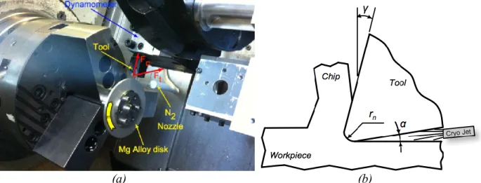
0.2 mm) were used. The width of cut was kept constant and equal to 4 mm. These tests were performed on both CNC and conventional lathe machines, under dry and cryogenic cooling conditions during machining. The CNC lathe machine was used to measure the forces during machining. Fig. 1 shows the experimental machining set-up, including the nozzle which was used to spray liquid nitrogen at -196 °C to the machined surface from the relief side of the cutting tool (nozzle diameter of 1 mm and pressure of 2 bar). The objective is to remove quickly the heat generated during machining from the machined surface. The conventional lathe machine was equipped with a quick-stop device used to quickly disengage the tool from the workpiece, in order to generate a surface with constant uncut chip thickness.
(a) (b)
Fig. 1. (a) Experimental machining set-up and (b) schematic representation of the tool geometry and application of the cryogenic jet.
The cutting force measurements were performed on a CNC lathe machine equipped with a Kistler 9121 dynamometer. The forces were measured in the tangential (or cutting, Fc) and radial (or
thrust, Fc) directions (Fig. 1).
Residual stresses in machined surface and subsurface were analysed by X-ray diffraction (XRD) technique and the sin2ψ method [11], using a Proto iXRD equipment. X-ray Cr-Kα radiation was used to determine the elastic strains in the (104) planes of the HCP crystallographic structure of the Mg alloy (152º Bragg angle). For each measurement, the irradiated volume was given by the product of a superficial rectangular area of 2.5 mm x 5 mm by the average penetration depth of the X-ray radiation in the AZ31B-O Mg alloy, which was about 19.5 μm. Residual stresses were determined in the machined surfaces and subsurface, in the circumferential (direction of the primary motion) and axial (direction of the disk axis) directions. To determine the in-depth residual stress profiles, successive layers of material were removed by electro-polishing, thus avoiding the reintroduction of additional residual stresses.
Results
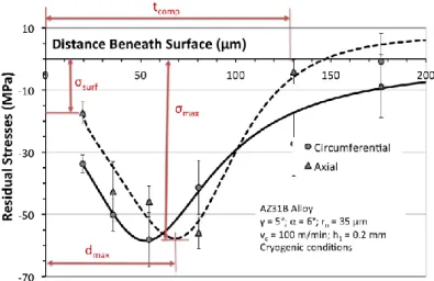
Fig. 2 shows the generic in-depth residual stress profiles measured in the circumferential and axial directions, for cryogenic machining of AZ31B magnesium alloy. Both residual stresses are
compressive, being the stress acting in the circumferential direction slightly more compressive than that stress acting in the axial direction.
For the range of all machining conditions investigated (Fig. 3 till Fig. 5), the residual stress in the circumferential direction is between -25 and -50 MPa at 19.5 µm below the surface (σsurf). As the
depth increases, the residual stress increases in compression, reaching a maximum value (σmax) of
about -100 MPa, then decreases until it reachs the zero stress. The residual stress acting in the axial direction has similar in-depth profile, but having lower values of the thickness of the layer affected by compressive residual stress. It should be mentioned that the thickness of the layer affected by compressive residual stresses (dcomp) couldn’t be determined with accuracy due to the difficulties to
determine the XRD pick position for depths greater than 100 μm. So, this parameter will not be evaluated in this article. Moreover, only the influence of the cutting conditions on the residual stress acting in the circumferential direction will be analysed, because this direction is coincident to the direction of the primary motion.
Fig. 2. Typical in-depth residual stresses profiles in the circumferential and axial directions and corresponding parameters that characterise these profiles.
Influence of cutting regime (cutting speed and uncut chip thickness)
Fig. 3 a) and b) shows the influence of the cutting speed and uncut chip thickness on the circumferential in-depth residual stress profile, respectively. This figure shows that when the cutting speed increases from 115 to 200 m/min the maximum value of the residual stress below surface (σmax) increases in compression, which is in accordance with previous studies [9]. Moreover, its
location (dmax) is moved further from surface. No changes were observed in the residual stress value
closer to the surface (σsurf), but previous studies [9] showed that this value may becomes less
compressive with the increase of the cutting speed.
(a) (b)
Fig. 3. Influence of the cutting speed (a) and uncut chip thickness (b) on the in-depth residual stress profiles in the circumferential direction, for dry cutting conditions.
Fig. 3 b) shows that when the uncut chip thickness increases from 0.05 to 0.1 mm, σmax slightly
increases in compression and the its location (dmax) is shifted closer to the surface. No changes were
observed in σsurf, which is in accordance with previous studies [9].
Influence of tool geometry (rake angle and cutting edge radius)
Fig. 4 a) and b) shows the influence of the tool rake angle and tool cutting edge radius on the circumferential in-depth residual stress profile, respectively. Fig. 4 a) shows that when the tool rake angle decreases from 5° to -6°, σsurf increase in compression. Identical trend is observed when the
tool edge radius increase from 35 μm to 70 μm (Fig. 4 b), which is in accordance with previous studies [9]. However, σmax and its location (dmax) aren’t affected by tool rake angle. However, this
maximum is slightly compressive when the tool edge radius increases.
(a) (b)
Fig. 4. Influence of the tool rake angle (a) and cutting edge radius (b) on the in-depth residual stress profiles in the circumferential direction, for cryogenic cutting conditions.
Influence of cooling conditions (dry vs cryogenic)
Fig. 5 shows the circumferential in-depth residual stress profiles under dry (solid lines) and cryogenic cooling (dashed lines) conditions.
(a) (b)
Fig. 5. In-depth residual stress profiles in the circumferential direction, for dry and cryogenic cutting conditions.
Both Fig. 5 a) and b) compare the residual stress induced by cryogenic cooling with that induced by dry conditions, although these figures are related to different tool rake angles. For each figure the cutting speed is slightly different between dry and cryogenic cutting conditions, but this cutting speed difference isn’t enough to affect the forces and temperatures, thus also not enough to affect
the residual stresses [9]. Fig. 5 a) and b) show that the effects of cryogenic cooling are more important when cutting tools with positive rake angle are considered. In this case, cryogenic cooling may induce slightly higher σsurf when compared to dry conditions. However, σmax is slightly
compressive for cryogenic cooling, although its location (dmax) isn’t affected by the cooling
conditions. So, in general, cryogenic cooling will induce a slightly deeper compressive residual stress profiles when compared to dry conditions.
Discussion
Table 1 resumes the influence of the cutting regime parameters (vc and h1), tool geometry (rn and
γ) and cooling conditions (dry and cryogenic) in the in-depth residual stress profile (σsurf, σmax and
dmax). In general, the use of more aggressive cutting conditions (higher vc, higher h1, larger rn,
negative γ and cryogenic cooling), which induce more plastic deformation at machined surface layers [9], will increase the compressive residual stresses in the machined surface and subsurface. However, some differences can be detected between the application of high values of the cutting regime parameters and the use of tools having a larger rn and negative γ.
Concerning to the cutting regime parameters, Fig. 6 a) compares two in-depth residual stress profiles, one obtained for lower values of vc and h1 (MG16) and the other for higher values of vc and
h1 (MG18). As shown in this figure, a combination of higher values of vc and h1 (MG18) produce an
increase of σmax but they don’t affect σsurf.
Table 1. Influence of the machining conditions on the circumferential in-depth residual stress profile.
Machining or Cutting Conditions σsurf σmax dmax
Cutting Regime Parameters
⬆Cutting Speed (vc) - Dry --- ↑↑ ↑
⬆ Uncut Chip Thickness (h1) - Dry --- ↑ ↓
Tool Geometry ⬇Rake Angle (γ) - Cryogenic ↑ --- ---
⬆Edge Radius (rn) - Dry ↑ ↑
---Cooling
Conditions Dry → Cryogenic ↓ ↑
---(a) (b)
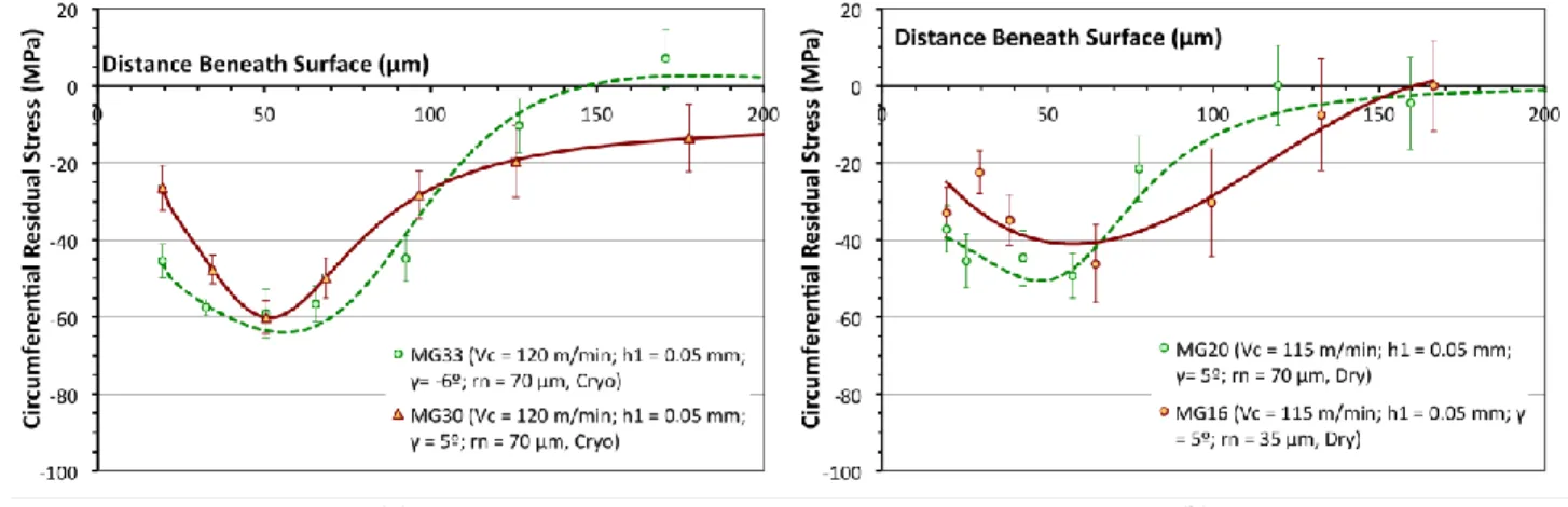
Fig. 6. Combined influence of the tool rake angle, cutting edge radius and cryogenic cutting conditions in the in-depth residual stress profiles.
Concerning to the tool geometry, Fig. 6 b) compares two in-depth residual stress profiles, one obtained for a smaller value of rn and positive γ (MG16) and the other for a larger value of rn and
negative γ (MG33). In this case, the combination of a larger value of rn and negative γ (MG33)
produce an increase of both σsurf and σmax. Moreover, the application of the liquid nitrogen directly
to the machined surface can also contribute to increase the compressive residual stresses (in particular σmax), since it efficiently removes the heat from the machined surface. However, in the
current machining tests this increase was not significant, which can be due to the low pressure (thus low flow rate) of the cryogenic jet.
Conclusions and outlook
Corrosion resistance is strongly dependent of the surface integrity of machined components, being the compressive residual stresses a key factor to increase de corrosion resistance. To increase the compressive residual stresses in machined components the proper selection of cutting conditions (including cutting regime parameters, tool geometry, tool material and metal working fluid) is required. This study shows that the increase of all cutting conditions can contribute to the increase of the compressive residual stresses in the surface layer induced by machining. However, the contribution of the tool rake angle and cutting edge radius seems to be more important when compared to other conditions, because they increase both residual stress value closer to the surface (σsurf) and residual stress below surface (σmax). The application of cryogenic cooling also contributes
to the increase of compressive residual stresses. In order to achieve a substantial increase in the compressive residual stress, the application of higher liquid nitrogen flow rate is required, which will be the objective of further machining tests.
Acknowledgements
The authors gratefully acknowledge to Seco Tools AB for offering the cutting tools and the financial support for residual stress measurements provided by FEDER through COMPETE and FCT under the project Pest-C/FIS/UI0036/2011. The authors also gratefully acknowledge the support of Prof. F. Rossi in performing the quick-stop tests.
References
[1] B. Denkena, A. Lucas, Biocompatible magnesium alloys as absorbable implant materials – adjusted surface and subsurface properties by machining processes, CIRP Ann. - Manuf. Technol. 56/1 (2007) 113–116.
[2] M. Alvarez-Lopez, M.D. Pereda, J.A. Del Valle, M. Fernandez-Lorenzo, M.C. Garcia-Alonso, O.A. Ruano, et al., Corrosion behaviour of AZ31 magnesium alloy with different grain sizes in simulated biological fluids, Acta Biomater. 6 (2010) 1763–1771.
[3] Y. Guo, M.P. Sealy, C. Guo, Significant improvement of corrosion resistance of biodegradable metallic implants processed by laser shock peening, CIRP Ann. - Manuf. Technol. 61 (2012) 583–586.
[4] H. Wang, Y. Estrin, H. Fu, G. Song, Z. Zuberova, The effect of pre-processing and grain structure on the bio-corrosion and fatigue resistance of magnesium alloy AZ31, Adv. Eng. Mater. 9 (2007) 967–972.
[5] Z. Pu, G.-L. Song, S. Yang, J.C. Outeiro, O.W. Dillon Jr., D.A. Puleo, et al., Grain refined and basal textured surface produced by burnishing for improved corrosion performance of AZ31B Mg alloy, Corros. Sci. 57 (2012) 192–201.
[6] I.S. Jawahir, E. Brinksmeier, R. M’Saoubi, D.K. Aspinwall, J.C. Outeiro, D. Meyer, et al., Surface Integrity in Material Removal Processes: Recent Advances, CIRP Ann. - Manuf. Technol. Keynote Pap. 60 (2011).
[7] Y. Guo, C. Saldana, W.D. Compton, S. Chandrasekar, Controlling deformation and microstructure on machined surfaces, Acta Mater. 59 (2011) 4538–4547.
[8] Z. Pu, J.C. Outeiro, A.C. Batista, O.W. Dillon Jr, D.A. Puleo, I.S. Jawahir, Enhanced surface integrity of AZ31B Mg alloy by cryogenic machining towards improved functional performance of machined components, Int. J. Mach. Tools Manuf. 56 (2012) 17–27.
[9] J.C. Outeiro, F. Rossi, G. Fromentin, G. Poulachon, G. Germain, A.C. Batista, Process Mechanics and Surface Integrity Induced by Dry and Cryogenic Machining of AZ31B-O Magnesium Alloy, Procedia CIRP. 8 (2013) 487–492.
[10] ISO3002/1, Basic Quantities in Cutting and Grinding - Part 1, Geom. Act. Part Cut. Tools - Gen. Terms Ref. Syst. Tool Work. Angl. Chip Break. (1982).
[11] I.C. Noyan, J.B. Cohen, Residual Stress - Measurement by Diffraction and Interpretation, Society for Experimental Mechanics, Springer-Verlag, New York, 1987.
DOI References
[1] B. Denkena, A. Lucas, Biocompatible magnesium alloys as absorbable implant materials - adjusted surface and subsurface properties by machining processes, CIRP Ann. - Manuf. Technol. 56/1 (2007) 113-116.
http://dx.doi.org/10.1016/j.cirp.2007.05.029
[2] M. Alvarez-Lopez, M.D. Pereda, J.A. Del Valle, M. Fernandez-Lorenzo, M.C. Garcia-Alonso, O.A. Ruano, et al., Corrosion behaviour of AZ31 magnesium alloy with different grain sizes in simulated biological fluids, Acta Biomater. 6 (2010) 1763-1771.
http://dx.doi.org/10.1016/j.actbio.2009.04.041
[3] Y. Guo, M.P. Sealy, C. Guo, Significant improvement of corrosion resistance of biodegradable metallic implants processed by laser shock peening, CIRP Ann. - Manuf. Technol. 61 (2012) 583-586.
http://dx.doi.org/10.1016/j.cirp.2012.03.125
[4] H. Wang, Y. Estrin, H. Fu, G. Song, Z. Zuberova, The effect of pre-processing and grain structure on the bio-corrosion and fatigue resistance of magnesium alloy AZ31, Adv. Eng. Mater. 9 (2007) 967-972.
http://dx.doi.org/10.1002/adem.200700200
[5] Z. Pu, G. -L. Song, S. Yang, J.C. Outeiro, O.W. Dillon Jr., D.A. Puleo, et al., Grain refined and basal textured surface produced by burnishing for improved corrosion performance of AZ31B Mg alloy, Corros. Sci. 57 (2012) 192-201.
http://dx.doi.org/10.1016/j.corsci.2011.12.018
[7] Y. Guo, C. Saldana, W.D. Compton, S. Chandrasekar, Controlling deformation and microstructure on machined surfaces, Acta Mater. 59 (2011) 4538-4547.
http://dx.doi.org/10.1016/j.actamat.2011.03.076
[9] J.C. Outeiro, F. Rossi, G. Fromentin, G. Poulachon, G. Germain, A.C. Batista, Process Mechanics and Surface Integrity Induced by Dry and Cryogenic Machining of AZ31B-O Magnesium Alloy, Procedia CIRP. 8 (2013) 487-492.