is an open access repository that collects the work of Arts et Métiers Institute of Technology researchers and makes it freely available over the web where possible.
This is an author-deposited version published in: https://sam.ensam.eu Handle ID: .http://hdl.handle.net/10985/8908
To cite this version :
10
Classical nitriding of heat
treatable steel
L. Barrallier
Arts et Métiers ParisTech, France
10.1 Introduction
Classical nitriding of heat treatable steel generates compressive residual stresses and hardened cases. Stress generation is directly linked to volume changes due to phase transformations during the nitrogen diffusion and the carbon co-diffusion processes, and the multiphase character of nitrided layers means that these stresses can be three dimensional in nature.
Hardness is related to MN nitride formation with a smaller size than the primary carbure ones and whilst the hardness and residual stress gradients cannot be directly linked, coupling the kinetics of the precipitation with N/C diffusion via a multiscale mechanical approach is necessary to understand this surface treatment.
Fatigue life can be increased by limiting crack propagation in the compressive case and by improving the intrinsic mechanical properties in the nitrided layers. Due to the temperatures at which nitrided layers are formed (up to 500°C for gas nitriding), they are very stable and mechanical relaxation is very limited.
The fatigue life of mechanical parts can be improved by surface engineering and the generation of compressive residual stresses (see Section 10.4). One such surface treatment, known as nitriding, is suitable for application to high performance parts that operate under severe loading and temperature conditions. Examples include: • the powertrain of the main gearbox in a helicopter (Razim, 1994; Boniardi et al., 2006), • shafts and bearings in airplane engines (Bhadeshia, 2012),
• crankshafts for automotive applications (Holzheimer and Naundorf, 1990), and • valve springs for internal combustion engines (Fujino et al., 2006).
10.2 Steels suitable for nitriding
Improvement of the fatigue life using nitriding requires steels which contain nitride-forming alloying elements. The steel composition should also display good fatigue properties of the unnitrided core. For surface fatigue (gears, bearings, etc.) hardness and residual stress gradients should be progressive from the surface to the core without steep gradients. For this type of application, the depth of the nitriding is mainly controlled by the time during which nitrogen diffusion takes place. Nitriding
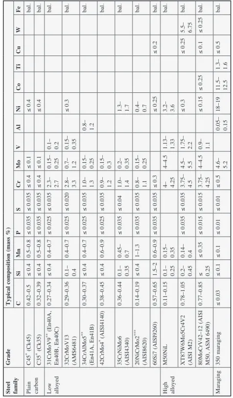
steel grades are low alloyed steels with 0.3–0.4 wt.% carbon, 1–5 wt.% chromium, and aluminium at less than 1.5 wt.%. Other elements are molybdenum for hardness and vanadium for the prevention of grain coarsening. Table 10.1 gives the main steel grades used in nitriding. Heat treatment prior to nitriding can further improve the mechanical properties of the material and Figure 10.1(a) illustrates a typical resulting microstructure. It should be noted that the size of carbides depends on the temperature at which the treatment occurs, as well as the time during which tempering takes place.
10.3 Microstructure and hardness improvement
The morphology of the nitrided layers depends on the core microstructure resulting from the transformation of chromium carbides into chromium nitrides. Although this microstructure must be stable during the nitriding treatment, the core hardness decreases by 20–30 HV if either the tempering temperature is too close to the nitriding temperature or the nitriding time is too long (more than 100 hours).
In order to improve the nitrogen diffusion rate at the gas–solid interface, pre-treatments may be performed. Parts are cleaned in order to remove oil contamination and are oxidized using either a solvent vapour with an acid or alkaline solution (Ghiglione et al., 1996). A phosphate coating treatment may also be used for surface activation.
Maraging steels can be gas nitrided at low temperature (below 500°C) to obtain a progressive hardness profile (Hussain et al., 1999). The main issue with high-alloyed steels with a high content of nitride-forming elements such as chromium is a thin diffusion zone with a thick and hard compound layer which is disadvantageous for fatigue applications. Austenitic stainless steels may be nitrided to improve wear resistance (see Chapter 3, Section 3.2) (Aghazadeh-Mohandesi and Priestner, 1983). For tool steels, the depth of the diffusion layer can be reached using low-pressure nitriding at around 103 Pa in order to increase the diffusivity of the nitrogen in the
presence of a high quantity of alloying elements (Gawronski, 2000). For high alloy steels, plasma nitriding is preferred to reduce the treatment temperature, increase nitrogen activity and prevent the onset of grain boundary precipitation (Yagita and Ohki, 2010). Table 10.2 gives some applications and uses of a number of nitrided steel grades for surface and volume fatigue life improvement.
Sometimes nitriding layers must be ground to remove compound, to improve the roughness and the precision of dimension of the parts. The choice of grinding parameters must be optimized in order to have compressive residual stress (Brinksmeier
et al., 1982) and avoid grinding burns (Shah, 1974).
Post-treatments may also be performed to improve the mechanical properties of nitrided parts such as PVD (Bader et al., 1998) or shot-peening (Ohue and Matsumoto, 2007; Croccolo et al., 2002). For high carbon steel, duplex treatments can be performed such as salt or gas nitriding followed by plasma nitriding in order to have better control of the nitrogen content (Streit and Trojahn, 2002).
T abl e 10 .1
Usua
l
ni
tr
idi
ng
st
ee
l
gr
ade
s
use
d
fo
r
m
ec
ha
ni
ca
l
wo
rkpi
ec
es
unde
r
fa
ti
gue
l
oa
di
ng
s
St ee l fa m ily G ra de T ypi ca l co mpo si ti on (ma ss % ) C Si M n P S Cr M o V Al Ni Co T i Cu W F e Pl ai n ca rb on C 45 * ( C k4 5) 0. 42 –0 .5 ≤ 0. 4 0. 5– 0. 8 ≤ 0. 03 5 ≤ 0. 03 5 ≤ 0. 4 ≤ 0. 1 ≤ 0. 4 ba l. C 35 * ( C k3 5) 0. 32 –0 .3 9 ≤ 0. 4 0. 5– 0. 8 ≤ 0. 03 5 ≤ 0. 03 5 ≤ 0. 4 ≤ 0. 1 ≤ 0. 4 ba l. L ow alloye d 31 C rMo V9 ** ( E n4 0A, E n4 0B , E n4 0C ) 0. 27 –0 .3 4 ≤ 0. 4 0. 4– 0. 7 ≤ 0. 02 5 ≤ 0. 03 5 2. 3– 2. 7 0. 15 – 0. 25 0. 1– 0. 2 ba l. 32 C rM oV 13 (AMS6 48 1) 0. 29 –0 .3 6 0. 1– 0. 4 0. 4– 0. 7 ≤ 0. 02 5 ≤ 0. 02 0 2. 8– 3. 3 0. 7– 1. 2 0. 15 – 0. 35 ≤ 0. 3 ba l. 34 C rAl Mo 5 ** (E n4 1A, E n4 1B ) 0. 30 –0 .3 7 ≤ 0. 4 0. 4– 0. 7 ≤ 0. 02 5 ≤ 0. 03 5 1. 0– 1. 3 0. 15 – 0. 25 0. 8– 1. 2 ba l. 42 C rMo 4 * (AI SI 41 40 ) 0. 38 –0 .4 5 ≤ 0. 4 0. 6– 0. 9 ≤ 0. 02 5 ≤ 0. 03 5 0. 9– 1. 2 0. 15 – 0. 3 ba l. 35 C rN iM o6 (AI SI 43 40 ) 0. 36 –0 .4 4 0. 1– 0. 35 0. 45 – 0. 7 ≤ 0. 03 5 ≤ 0. 04 1. 0– 1. 4 0. 2– 0. 35 1. 3– 1. 7 ba l. 20 Ni C rMo 2 ** * (AI SI 86 20 ) 0. 14 –0 .1 9 ≤ 0. 4 1– 1. 3 ≤ 0. 03 5 ≤ 0. 03 5 0. 8– 1. 1 0. 15 – 0. 25 0. 4– 0. 7 ba l. 60 Si 7 (AI SI 92 60 ) 0. 57 –0 .6 5 1. 5– 2 0. 6– 0. 9 ≤ 0. 03 5 ≤ 0. 03 5 ≤ 0. 3 ≤ 0. 25 ≤ 0. 2 ba l. H ig h al lo ye d M5 0Ni L 0. 11 –0 .1 5 0. 1– 0. 25 0. 15 – 0. 35 4– 4.25 4– 4. 5 1. 13 – 1. 33 3. 2– 3. 6 ba l. X T 87 W 6M o5 C r4 V 2 (A IS I M 2) 0. 78 –1 .0 5 0. 2– 0. 45 0. 14 – 0. 4 ≤ 0. 03 5 ≤ 0. 03 5 3. 75 – 4. 5 4. 5– 5. 5 1. 75 – 2. 2 ≤ 0. 3 ≤ 0. 25 5. 5– 6. 75 ba l. 80 Mo C rV4 2– 12 ( AI SI M5 0, ASM 64 90 ) 0. 77 –0 .8 5 ≤ 0.25 ≤ 0. 35 ≤ 0. 01 5 ≤ 0. 01 5 3. 75 – 4. 25 4– 4. 5 0. 9– 1. 1 ≤ 0. 15 ≤ 0. 25 ≤ 0. 1 ≤ 0. 25 ba l. Ma ra gi ng 35 0 m ar ag in g ≤ 0. 03 ≤ 0. 1 ≤ 0. 1 ≤ 0. 01 ≤ 0. 01 ≤ 0. 5 4. 6– 5. 2 0. 05 – 0. 15 18 –1 9 11 .5 – 12 .5 1. 3– 1. 6 ≤ 0. 5 ba l. *E N1 00 83 , **E N1 00 85 , ** *E N1 00 84 st an da rd sz = zcore t = t0 z ≠ zcore t ≠ t0 M3C Globular MN Semi-coherent MN 20 µm 20 µm 10 nm (a) (b) M23C6 Martensite laths
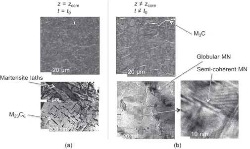
Figure 10.1 Microstructure of base material (a) and nitride layers (b), 32CrMoV13 oil quenched and tempered, 96 h gas nitriding at 560°C.
Table 10.2
Applications for fatigue life of nitriding steel grades
Steel family Grade Application
Plain carbon C45* (Ck45) Academic research, not really used for high loading parts C35* (Ck35)
Low alloyed 31CrMoV9** (En40A, En40B, En40C)
Shafts, crankshafts, gears 32CrMoV13 (AMS6481)
34CrAlMo5** (En41A, En41B) 42CrMo4* (AISI4140)
35CrNiMo6 (AISI4340) 20NiCrMo2***(AISI8620)
60Si7 (AISI9260) Springs
High alloyed M50NiL Bearings
XT87W6Mo5Cr4V2 (AISI M2) Tools 80MoCrV40 (M50, ASM 6490) Bearings
Maraging 350 maraging For high loadings and corrosion resistance
The mechanical properties of the nitrided layers are directly linked to the microstructure and precipitation phenomena that occur during nitrogen diffusion. With increasing hardness, compressive residual stresses are generated due to phase transformation and/or precipitation.
Figure 10.1(a) illustrates a typical initial microstructure for chromium steel grades after oil quenching and tempering, i.e. ferrite with M23C6 (M = Cr, Fe), M7C3 (M
= Cr, Fe) or VC carbides (depending on the steel composition). Globular MN (M = Cr, Fe) precipitation occurs in a ‘chaplet’ shape (Locquet et al., 1997) as shown in Figure 10.1(b). Free chromium in tempered martensite is used to form fi ne and semi-coherent MN (M = Cr, V, Mo) nitrides. Iron substitution within MN nitrides (Ginter et al., 2006) or local lattice strain at the precipitate–matrix interface increases nitrogen solubility and can explain the observed excess of nitrogen (Somers et al., 1989). The initial carbides (M23C6, M7C3) are transformed to the MN nitrides and the
M3C (M = Cr, Fe) cementite during the nitrogen diffusion. This mechanism explains
the coupled carbon and nitrogen diffusion. In order to limit any potential weakness of the nitride layers, the grain boundary cementite should not form a continuous network, which involves optimization of the processing parameters. The MN nitrides formed are smaller than the initial carbides, which increases the hardness of the nitrided layers.
In the case of steel, the mechanical properties can be linked via the tensile the strength sy to the Vickers hardness H by a Tabor-type law (Tabor, 1951):
H = a sy with a ≈ 0.29 – 0.3 [10.1]
For nitrided layers (32CrMoV13 steel), Locquet (1998) showed that the a coeffi cient is close to 0.4. Some authors were able to measure the local yield stress using nanoindentation experiments and inverse methods (Jacq et al., 2003).
10.4 Nitriding-induced stress in steel
Nitriding reduces the risk of distortion (Machlet, A. Fry, Pye, 2003) due to the internal stresses associated to nitrogen diffusion and phase transformations. Nitriding induced compressive stresses were fi rstly evaluated by R.B. Waterhouse by comparison with compressive stress obtained in sulphidized coatings from the defl ection of the specimen (Waterhouse, 1965). Residual stresses are found throughout the multiscale in-depth incompatibility of stress-free strain. In other ways, the residual stress fi eld and associated elastic strain exists to make the total strain compatible and satisfy the Saint-Venant compatibility equations.
The stress-free strain esf is directly related to the microstructure transformations that occur during nitriding:
• Volume changes DVV tr can be caused by several phenomena during the co-diffusion of nitrogen and carbon:
– modifi cation of the phase composition such as the solubility of carbon and nitrogen in ferrite and the contents of alloying elements in MN, M23C6 or M3C precipitates,
– phase development such as MN or M3C precipitates from M-containing ferrite and/or
M23C6 carbides,
– phase transformations such as M23C6 carbides.
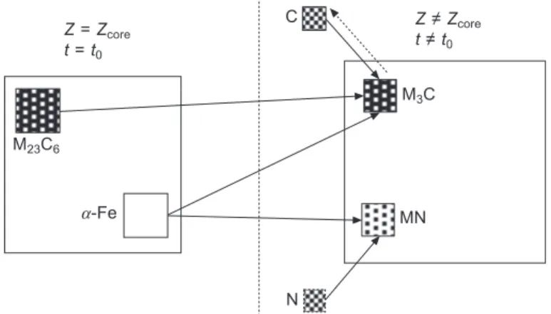
Figure 10.2 shows schematically how the microstructure evolves from the base to the nitrided case. The quantity and specifi c volume of the crystalline phase defi nes how large the volume change will be. Calculation of the volume change must take into account both the diffusion of nitrogen and co-diffusion of carbon (Jegou et al., 2010).
Figure 10.3 gives the specifi c volumes of the main phases found during nitriding of low carbon alloying steels. The total volume change may be obtained by consideration of the local volume change pondered by the volume fraction of each phase.
• The volume change DV
V th
due to thermal shrinkage on cooling from the nitriding temperature
Tn (500–560°C) to room temperature Tr and linked to the volume fractions and thermal
expansion coeffi cients a of the different phases present.
∑ Plastic straining ep due to the mechanical behaviour of ferrite. A local elastoplastic law
can be used to link this deformation with stresses. Hardening, which depends on ferrite composition. For precipitates in the nitrided case, such as MN nitrides, only elastic behavior needs to be considered (Barrallier and Barralis, 1994). Z = Zcore t = t0 Z ≠ Zcore t ≠ t0 C N M3C M23C6 MN a-Fe
Figure 10.2 Schematic representation of volume variation during nitriding of low alloyed steels.
Fe3N Fe3C Fe4N
125.8 127.1 130.4 138.9 144.9 145.4 161.3
a-Fe Cr23C6 Cr7C3 CrN Specifi c volume
cm3.kg–1
The induced strain is small and can be neglected. Some authors consider creep phenomena (Buchhagen and Bell, 1996; Daves and Fischer, 1994) but this will not be considered here. Neither dislocations nor residual plastic straining have been observed, except at the matrix–precipitate interface (Barrallier et al., 1997). Note that stress relaxation (time dependent evolution of the stress state) should not be confused with stress redistribution close to the surface.
Due to the multiphase character of the material, the macroscopic properties (denoted
Xˆ) should be distinguished from the microscopic properties (denoted Xfi for phase
fi). The mechanical properties are three-dimensional and may be expressed using tensor notation (X for second-order tensors and X for fourth-order tensors).
Several authors have proposed methodologies for modelling the residual stress distribution. Buchhagen and Bell (1996), for example, have taken into account the nitrogen concentration profi le in the substrate matrix, the volume divergence between the matrix and the increasing volume fraction of nitrides, the dissolution of carbides during the nitriding process, the relaxation of stress at the nitriding temperature and the build-up of thermal stress on cooling. Other similar models describe the origin of the volume change in terms of coupled effects between lattice strains, volume changes accompanying precipitation, thermal effects and phase composition changes (Oettel and Schreiber, 1989; Mittemeijer, 1983). Vives Diáz et al. (2008) employed a phenomenological approach for the macroscopic residual stresses of binary nitrided iron-based alloys based on the different precipitation mechanisms of the nitrides (semi- and incoherent precipitates and discontinuous precipitation).
Using an incremental time dependent approach (where X˙ = ∂X/∂t), at the nitriding temperature, the macroscopic strain tensor rate ˆe can be expressed as a function of the elastic ˆee and the stress-free strain ˆesf:
e ee e + ee ee ee eˆ = ˆeeeeeeeeee+ + eeeeeeeeeeeeeeeeˆˆˆˆˆˆˆˆˆsssssfsssssffffff = = = eeee + eeeeeeeeeeeeeeˆˆˆˆˆˆˆˆˆeeeeeee eeeeeeeeˆˆˆppppppp + + + + +eeeeeeeeeˆˆˆtttttrttr [10.2] with
rot(rot( ˆe )) = 0 [10.3]
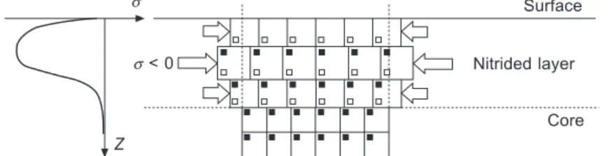
Equation [10.3] is illustrated in Figure 10.4. Due to the positive value of volume change in the nitrided layer, a state of compressive stress is generated. The macroscopic mechanical equilibrium is expressed:
s s < 0 Z Surface Nitrided layer Core
Figure 10.4 Schematic representation of residual stress generation due to the volume change during nitriding.
div = 0 ˆs
[10.4]
Scale transition relations between the macroscopic and microscopic scales render the material heterogeneous through mixing. Macro-strains or stresses are a function of local strains or stresses weighted by the volume fractions of the phases, yfi (microscopical value is noted to refer to the phase fi):
sssssssssssssssˆ =
S
S
iiyyyffffffffffiiiisssssssssssssssffffffffffiiii [10.5]and
eeeeeeeeeeeeeeeeeeeeeeeˆ =
S
S
iiiiyyyf ff ff ff ff ff ff ff ff ff fiiiieeeeeeeeeeeeeeeeeeeeeeeiiii [10.6]Local stress-free strains, effffsfii , can be described using the Eshelby inclusion and Kröner approaches (Kröner, 1967):
eeefffffii eee e e ee ee e e e I e I eee I eee I ee ee e I e I ee ee e = ( = ( e e = ( e eee = ( eee ee ee e = ( e ee ee e e e I e I e + e e I e I eeeee II + eeeee II ee ee e I e I ee ee e + e ee ee e I e I ee ee e ) ) e e ) e eee ) eee e I e I e ) e e I e I eeeee II ) eeeee II ee ee e I e I ee ee e ) e ee ee e I e I ee ee e U e ( ( U) : ( ( ) : ( e U e U e II U e II U e I e I e U e U e I e I eeeee II U eeeee II U ee ee e I e I ee ee e U e U ee ee e I e I ee ee e e e ) e e U e U e ) e e e e I e I e ) e e I e I e U e U e I e I e ) e e I e I eeeeeeeee IIII ) )U eeeeeeeee IIII U ee ee e I e I ee ee e ) e ee ee e I e I ee ee e U e U ee ee e I e I ee ee e ) e ee ee e I e I ee ee e e e :e e U e U e :e e e e I e I e :e e I e I e U e U e I e I e :e e I e I e e ee ee e I e I ee ee e :e ee ee e I e I ee ee e U e U ee ee e I e I ee ee e :e ee ee e I e I ee ee e IIII U e IIII U e I e I e e e I e I e U e U e I e I e e e I e I eeeeeeeeeee IIIIIIIIIIII UUUUUU eˆˆˆeeeeeeeeee+ + ( ( ( ( IIIIIIIIIIII + + UUUUUU ( ( + SSS+ III eeee ee ff ef e effsfii e esf e e esf e – e e e )ˆ [10.7]
where I is the fourth-order unity tensor, U the polarization tensor and S the Eshelby tensor describing the shape of the inclusion (precipitates and ferrite). The phase transformation strain rate efffftrii due to the precipitation/dissolution of phase fi can be linked to the macroscopic value ˆ
due to the precipitation/dissolution of phase
due to the precipitation/dissolution of phase etr by the relation:
eeeeeeeeeeeeeeeeeeeˆtrtr =
S
S
iiyyy ffffffiiieeeeeeeeeeeeeeeeeeefffftrii [10.8]where yyyfffiii is the variation with time of the volume fraction of phase fi. The local
deformations can be written: eeeeeeeeeeefffffiii eeeeeeeeeeefffffffiii eeeeeeeeeeefffffffiii eeefffffffiii eeefffffffiii eeefffffffiii e e e ee e e e esf eeeeeee eeeeppp eeeetr e =e e e e e e e e e e e e ef ef e e e e ef ef e e + e e e + e e e e e ef ef e e + e e ef ef e e e = eeeeeeeeeeeeeeeeeeffffff + + + eeeeeeeeeeeeeeeeeeffffff + + +eeeeeeeeeeeeeeeeeeffffff [10.9] and the local elastic properties of the phases can be expressed by:
sssssssssssssssssssssssssssssssssssssssssssssssssssssssssssssssssssssssssssssssssssssfffffffffffffffffffffffffffffffffffffffiiiiiiiiiiiiiiiii = = =CCCCCCCCCCfffffffffffffffffffffffffffffffffffffffiiiiiiiiiiiiiiiii:::::::::eeeeeeeeeeeeeeeeeeeeeeeeeeeeeeeeeeeeeeeeeeeeeeeeeeeeeeeeeeeeeeeeeeeeeeeeeeeeeeeeeeeeeffffii [10.10]
where Cffiii is the stiffness tensor of phase fi. If the mechanical behaviour of a given
phase is elastoplastic, the stress rate can be linked to the plastic strain rate by the hardening law gfi: sssssssffffffffffiiiii gffffffffffiiiii eeeeeeeffi p s = e s e sf f e s = e sf f e s e sf f e s i i e sf f e s = e sf f e s i i e sf f e s e ))) s e ) s e sf f e s e ) sf f e s ii ii effff))) s i i e s e ) s i i e sffffii ffffii e ) sf f e s i i e sf f e s e ) sf f e s i i e sf f e sffffii ffffii e ) sf f e s i i e sf f e s e ) sf f e s i i e sf f e s effffiiii)) s g e s e ) s g e s e sf f e s g e sf f e s e ) sf f e s g e sf f e sffffffffiiii ggffffffffiiii e ) sf f e s i i e sf f e s g e sf f e s i i e sf f e s e ) sf f e s i i e sf f e s g e sf f e s i i e sf f e s ((((epp))))) s e ) s (e s e ) s e [10.11] In order to derive the residual stress, Eqs [5.2]–[5.1] should be simultaneously solved using appropriate initial and boundary conditions.
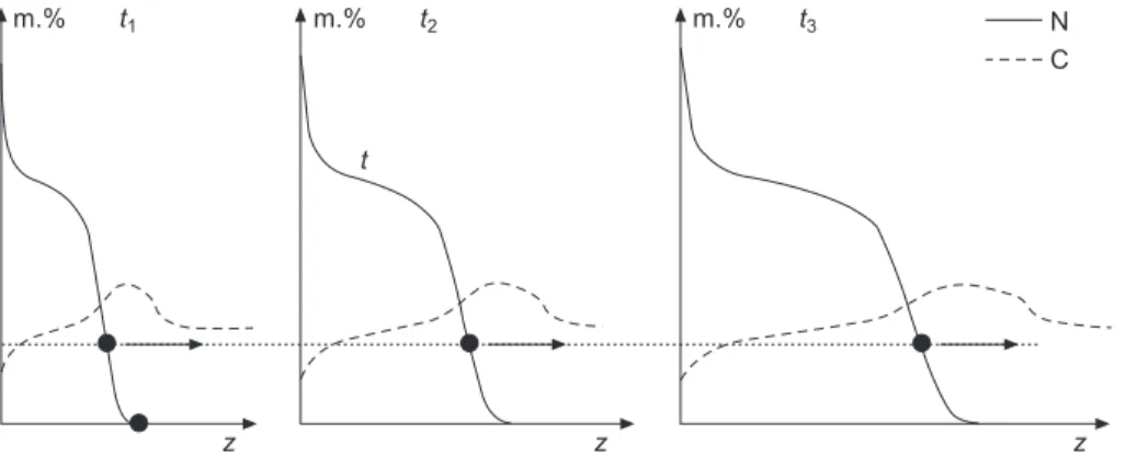
This mechanical model can be linked to a diffusion/precipitation model in order to calculate phase transformations (Jegou et al., 2010). Using this approach, stress relaxation close to the surface can be explained by the co-diffusion of carbon and the kinetics of the precipitation/dissolution of the nitrides and carbides. Figure 10.5 shows the schematic evolution of nitrogen and carbon profi les during the nitriding of a low alloy steel. The surface concentration depends on nitrogen activity and the carbon content and is maintained at a constant value when a compound layer is
present at the surface. Due to the interaction with nitrogen, diffusion of carbon occurs generating a carbon-depleted zone close to the surface and a carbon-enriched zone ahead of the nitrogen front. The diffusion front diffuses into the steel as a function of √t. For a given depth, the nitrogen concentration increases with time, while the carbon concentration progresses through a maximum value. Figure 10.6 illustrates the volume fraction of precipitates in the diffusion layer as a function of depth and time as determined by the thermodynamic software Thermo-Calc®.
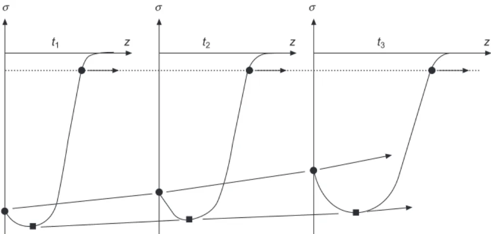
At a given depth, the volume fraction of the alloyed cementite M3C follows the
evolution of the carbon content implying that the volume variation accompanying the dissolution/precipitation of phases increases for a certain time/depth and decreases after/close to the surface as shown Figure 10.7. A positive increment in volume generates a compressive residual stress and a negative increment elastically unloads the material and leads to a reduction in the level of compressive stress. In Figure 10.8, schematic evolution of the residual stress profiles are shown in comparison to the observed ones and a close correlation is observed. Also, the compressive surface stresses and the maximum of the latter decrease with time (Barralis et al., 1986). During cooling, it is assumed that only thermal strain occurs and that no significant transformation strains exist. In fact, there is a very small reduction of the lattice solubility
vol.% t1 vol.% t2 vol.% t3
z z z
CrN M3C M23C6/M7C3
Figure 10.5 Schematic evolution of volume fraction of carbides and nitrides during nitriding of low alloyed steels.
m.% t1 m.% t2 m.% t3 N
C
t
z z z
of nitrogen in ferrite and this nitrogen can either form a≤-Fe16N2 or condense onto
MN precipitates with an effective increase of the size of these particles. Hoffmann
et al. (1995) showed that during cooling, the compressive stresses in ferrite close to
the surface decrease slightly. This shows that residual phase-specific macro-stresses (or pseudo-stresses or order II stresses) are different from the overall macro-stress (or order I macro-stress) in the sample. Figure 10.9 illustrates the residual macro-stresses in ferrite (pseudo-macro-stresses) analysed using X-ray diffraction in comparison to the macro-residual stress evaluated from the deflexion of a plate (Goret, 2006). The value of the sample-averaged macro-stress is twice that of the average phase-specific stress in ferrite.
In order to optimize the design of parts, numerical modelling of nitriding has been developed using a finite-element approach (Daves and Fischer,1994; Cavaliere
et al., 2009; Arimoto et al., 2010). In this modelling, the local geometry of parts
DV/V% DV/V% DV/V% DV/Vmax t1 t2 t3 z1 z2 z z1 z2 z z1 z2 z s s s t1 z t2 z t3 z
Figure 10.7 Schematic evolution of volume change during nitriding of low alloyed steels.
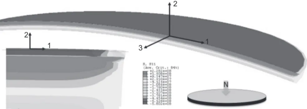
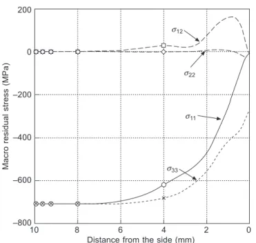
and their influence on the nitrogen diffusion process can be taken into account and residual stress fields calculated. Figure 10.10 (and Plate IV between pages xxx and xxx) shows the residual stress component in a single direction (1) of a nitriding disc where the other faces have been protected by a copper plating (Barrallier et al., 2008). Figure 10.11 shows the macro-stress components 200 mm below the surface from the centre to the protected side of the disc. The biaxial residual stress state at the centre of the disc (s11 = s33, s22 = 0) changes to a uniaxial stress state at the
edge of the disc (s11 = s22 = 0).
X-ray diffraction (micro) Deflexion (micro) 0 200 400 600 800 1000 1200 Depth (µm) Resi dual stress (MPa) 200 0 –200 –400 –600 –800 –1000
Figure 10.9 Macro-residual stress (deflexion) and micro-residual stress (XRD in ferritic phase), 32CrMoV13 gas nitrided, 120 h at 560°C.
2
1 3 1
2
Figure 10.10 Deflexion of one-side nitride plate disc, simulation of nitriding using FEM; stress in Pa (Barrallier et al., 2008).
The true residual stress field is a function of the local shape of the parts such as the fillet between the two teeth for a gear or the groove for a shaft. In this case, because of the local geometry, the stress measurement can be performed using a non-destructive diffraction method without removal of matter (Goret et al., 2006). Mechanical parts can be subjected to multiple thermo-mechanical loading cycles and the stability of residual stress with time is an important factor for the behaviour of nitrided layers. If the temperature in service is below the nitriding temperature, no evolution of residual stress will occur. As long as no metallurgical transformation occurs, such as precipitation/dissolution of precipitates, no variation of residual stress is apparent as no local volume changes occur. At in-service temperatures close to the nitriding one, the residual stress profile evolves as a function of temperature level and time (Barrallier et al., 1993).
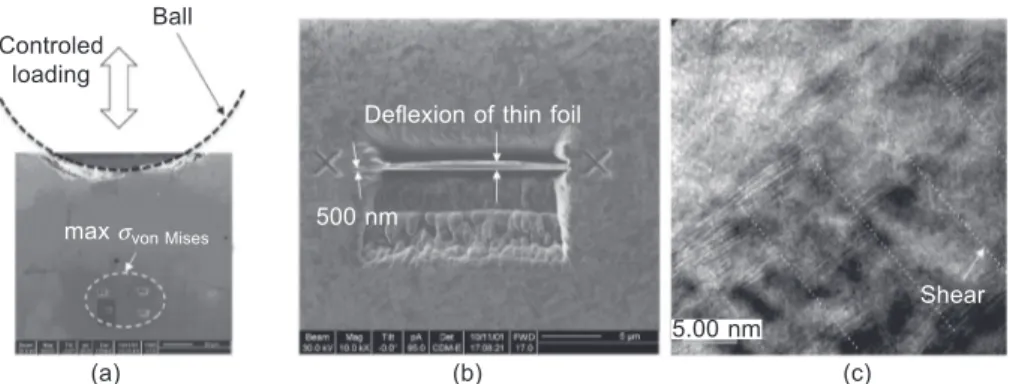
Stress relaxation due to mechanical loading is dependent on the level of the applied stress, and modification of the microstructure of a nitrided alloy can be observed through hardness measurements in the case of contact fatigue. Figure 10.12(a) shows the results of a micro-ball attrition test on 32CrMoV13 steel. The loading was applied using a 100Cr6 steel ball with controlled displacements. Several thin foils were taken for TEM investigation at the maximum stress. In Figure 10.12(b), the thin foil (15 ¥ 6 ¥ 0.5 mm3), which was machined using a focused ion beam
microprobe, is curved due to relaxation of the local compressive stress field. Using TEM, it was possible to identify semi-coherent MN nitrides sheared by dislocation sliding (Figure 10.12(c)). A decrease of CrN scale increases the local hardness of the
s12
s22
s11
s33
10 8 6 4 2 0
Distance from the side (mm)
Macro residual stress (MPa) 200 0 –200 –400 –600 –800
Figure 10.11 Effect of triaxial stress close to the border of a one-side nitrided disc (Goret, 2006).
material. There is no change in the volume fraction of the MN nitrides, but plastic deformation does occurs resulting in residual stress modification and ultimately damage.
10.5 Nitriding and improved fatigue life of steel
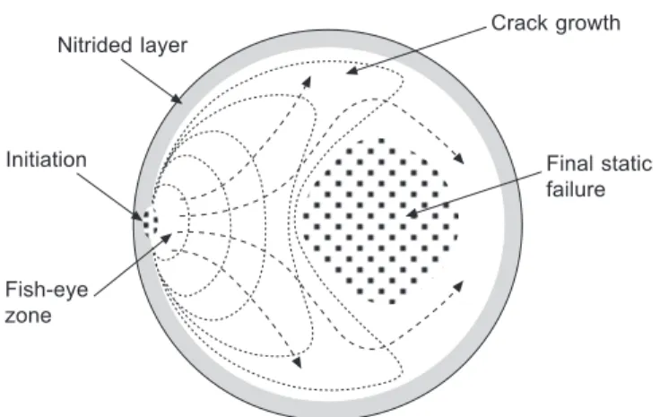
Under mechanical cyclic loading with industrial steels the damage is generally localized at stress concentrators such as inclusions (sulphurs, oxides), grain boundaries or large precipitates (De la Cruz et al., 1998). Due to hardening and residual stress in the nitrided layers, initiations are generally localized in the base material close to the diffusion zone for un-notched parts. For notched parts, initiation of cracks can occur at the surface or very close to the surface (Limodin and Verreman, 2010). The morphology of the fracture surface of an un-notched specimen is shown in Figure 10.13. Crack propagation progresses into the base material from the stress concentration with a fish-eye-type shape. In the nitrided layers the cracking is brittle and partially intergranular and the fracture toughness is generally low. Şengul and Çelik (2011) found a fracture toughness of 3.7 MPa.m1/2 for plasma nitrided 42CrMo4
(AISI4140) steel compared to 50MPa.m1/2 for the base material.
The work of Hengstenberg and Mailänder showed that nitriding leads to an improved fatigue limit for steel (Hengstenberg and Mailänder, 1930). The fatigue limit improvement is linked to the depth of the nitride alloy and as well as any post-treatment such as grinding (Barralis and Castex, 1986; Castex et al., 1987). Residual stress combined with the hardening effects has been shown to improve the fatigue strength of nitride 34CrAlMo5 (En41B) steel grade by more than 25% (Jones and Martin, 1977).
The nitriding temperature is also important with crack initiation occurring more quickly for notched specimens at higher temperature due to the lower hardness
Controled loading
Ball
max svon Mises 500 nm
Shear Deflexion of thin foil
5.00 nm
(a) (b) (c)
Figure 10.12 Effect of cyclic loading of nitriding layer microstructure: (a) position of thin foil at the maximum of Hertz stress; (b) deformation of thin foil due to the residual stress field; (c) shearing of semi-coherent MN nitrides due to dislocation movement (white dash lines).
obtained (Braam et al., 1997). For un-notched specimens, the effect of temperature is negligible because the initiation of cracks occurs in the base material.
The type of loading is also an important factor. For tension–compression loading, the benefits of nitriding are not clear because the core of material is more heavily loaded than the nitrided layer. In this case, for low-cycle fatigue (LCF), the ratio between nitrided and un-nitrided cross sections defines the distribution of residual stress (Guagliono and Vergani, 1997). When the notch severity increases, the nitrided layer is more stressed and the high-cycle fatigue (HCF) strength, for bending loading, increases in comparison with an un-nitrided specimen.
Figure 10.14 shows schematically the Wöhler (S-N) curves of notched nitrided and un-nitrided specimens for LCF and HCF. For deep nitriding depths, the S-N curve Figure 10.13 Schematic representation of crack initiation and crack propragation for a rotating bending loading of nitrided shafts.
Crack growth Final static failure Fish-eye zone Initiation Nitrided layer
Low-cycle fatigue High-cycle fatigue
Surface crack inititation Core crack inititation
Nitrided depth effect Nitrided material Base material Stress amplitude 103 104 155 106 107 108 Number of cycles
Figure 10.14 Schematic S-N curves for un-nitrided and nitrided notched specimen with the influence of nitrided depth.
is displaced towards high stresses and cycles. Unlimited fatigue strength is reached at 107–108 cycles. The S-N curve can be plotted for different probabilities p(N) of
failure as shown in Figure 10.15(a). For uniaxial loading, the S-N curve depends on the stress ratio Rs = smin/smax where smin and smax are the minimum and maximum
applied stresses, respectively. Figure 10.15(b) shows the effect of average stress on the S-N curve for a 50% probability p of failure. With a tensile–compressive loading with b (Rs = 1) and a cycle number to failure of Nf = 106 cycles, cracks occur when the loading amplitude is greater than the fatigue limit sf (point N¢).
HCF fatigue behaviour of material can be approached using fatigue criteria. The uniaxial fatigue criterion based on the Goodman–Gerber diagram can be used to explain the hardening effect of nitriding (Cowling and Martin, 1981). This type
p(N) p(N) p(N) N N N p = 0.95 p = 0.5 p = 0.05 103 104 105 106 107 108 Number of cycles (a) Stress amplitude s s sMax sMax smin smin t t Rs = –1 Rs > 0 p = 0.5 N’ N Nf
Average stress effect
103 104 105 106 107 108 Number of cycles (b) sf Stress amplitude
Figure 10.15 (a) S-N curves for different probability p(N) to failure; (b) S-N curves for different loading ratios Rs (effect of mean stress).
of approach cannot explain the effect of residual stresses. With a triaxial fatigue criterion, such as in Crossland diagrams, these effects can be taken into account (Chaussumier, 2000). The main assumption for a mechanically applied load sa is a simple function of time:
sa(t) = sM + salt(t) · f(t) [10.12]
where sM is a mean stress tensor independent of the time. The tensor salt(t) represents the alternate stress depending on time t. This approach is restrictive; the stress components of the applied stresses should not be out of phase with the time. A Crossland diagram is based on the drawing si of the von Mises alternate stress ssssssssssssssMMalaltt = ( = ( trtr(((((ssssssssssssssDalaltaltDDt ))))))
2 ( 2) ( )1/2 3 s 3 s s 2 s s 2 s
s s as a function of the maximal hydrostatic pressure
pHMAXMAXMAXXXXXXXXXXXXXXXXXXXX = = M M M M M111 axax(t(t(t(tr((t(tr(r(r( aaaaaaaaaaaaaaaaaaaaaa)) 3 M3 M s X sa X a where tr( )( ) + 11 11 22 22 s s ( )s s ( ) =ssa = ssa sss2222 + +sss ( )a a ( )ssa ssa ( )s s ( )a a ( )s s ( ) =ssa = = =ssa ssssaaaa + + + + + +ssssaaaa (Crossland, 1956). The effect of the hydrostatic pressure on the crack initiation and its propagation is taken into account with this criterion. Some other fatigue criteria exist depending on the material behaviour and could be used with the same approach. The Crossland line of the base material can be determined using two or more basic S-N curves with different uniaxial loading ratios (Figure 10.16(a)). Generally rotating bending (Rs = – 1,
sHal
with different uniaxial loading ratios (Figure 10.16(a)). Generally rotating bending al
with different uniaxial loading ratios (Figure 10.16(a)). Generally rotating bending t
HMAXMAXMA
p = 3) and alternate twist ( pHMAX = 0) fatigue tests can be chosen with one or two other repeated bending loading (Rs ≥ 0). The half space below
the Crossland line represents the mechanical loading which do not induce failure (for p probability and Nf cycles to failure). The N and N¢ points on the (Rs = – 1) line are deduced from the S-N curve. For nitrided material, the determination of the Crossland line depends on the depth and can be related to the hardness and the local yield stress using Eq. [10.1]. The effect of microstructure change shifts the line to higher stresses; the slope remains the same (Terres et al., 2010). Assuming no residual stresses, it is possible to draw in a Crossland diagram the fi gurative points of loading for the whole part inside or outside the nitrided layer. In Figure 10.16(b), if the fi gurative point M is below the Crossland line, no failure occurs for the selected (Nf, p) conditions. If the point is beyond the Crossland line, cracking occurs before cycles to failure Nf. The macroscopical residual stresses sRS =
s s 11 22 0 0 0 s 0 0 s22 0 0 22 0 0 0 0 Ê Ë Á Ê Á Ê Á Á Á Á ÁËÁË Á Á Á ˆ ¯ ˜ ˆ ˜ ˆ ˜ ˜ ˜ ˜ ˜¯˜¯ ˜ ˜ ˜ due to the nitriding can be added to Eq. [10.12]. Nitriding residual stresses are not time dependent (no stress relaxation assumption) implying that the variation of the alternate stress is equal to zero and only the maximum of hydrostatic stress is modifi ed by the value 1/
3(s11 + s22). For compressive residual stress this value is
negative and the fi gurative point M is moved to M¢. The fatigue life improvements are cleary due to the coupled effect of the hardening and the compressive residual stresses of the nitride layer.
Post-treatment after nitriding affects the microsctructure of the nitrided layers and can have benefi cial or detrimental effects on fatigue performence. Grinding can induce tensile residual stresses even if the hardness is increased and the fatigue
strength reduced. With shotpeening after nitriding, the fatigue strength can increase by 10% for a 32CrMoV13 steel grade (Freddi et al., 1997).
The benefits of nitriding are also apparent for low surface stresses (surface fatigue and fretting fatigue) such as in the case of contact between two parts. The fretting fatigue strength associated with nitriding can increase by 60% compared with untreated steels (Mutoh and Tanaka, 1988). For rolling contact fatigue (bearings), deep nitriding appears to be a good alternative to conventional high temperature bearing steels which are hardened and tempered at low temperature.
The core material has excellent toughness for structural functions and high rotational speeds. The nitrided layer features high hardness, high compressive residual stresses and superior rolling contact properties for aerospace components (Girodin, 2008).
For Nf cycles to failure and p probability salt vM N Rs = –1 Rs > 0 3 0 (a) pHMAX N¢
Figure 10.16 Crossland fatigue criterion used for nitriding (a) Crossland line for Nf cycles to
failure and for a p failure probability, no failure for point N, failure for point N’; (b) influence of hardness on the fatigue limit and compressive residual stress on mechanical loading.
For Nf cycles to failure and p probability salt vM M¢ M (b)0 Core pHMAX Hardness effect Compressive residual stress effect Nitrided layer
References
Aghazadeh-Mohandesi J and Priestner R (1983), ‘Effect of nitriding at low nitrogen partial pressures on yield and fatigue in some stainless steels’, Metals Technology, March, 10, 89–95.
Arimoto K, Ikuta F, Yamanaka S and Funatani K (2010), ‘Development of simulation tool for predicting distortion and residual stress in nitrided parts’, International Journal of
Microstructure and Materials Properties, 5, 4–5, 386–398.
Bader M, Spies HJ, Hock K, Broszeit E and Schroder HJ (1998), ‘Properties of duplex treated (gas-nitriding and PVD -TiN, -Cr2N) low alloy steel’, Surface and Coatings Technology,
98, 891–896.
Barralis J and Castex L (1986), ‘Improvement of rotation bending and rolling contact fatigue of nitrided 32CDV13’, Residual Stress. Sci. and Tech. Int. Conf., Garmisch–Partenkirchen, 2, 679–686.
Barralis J, Castex L and Chaize JC (1986), ‘Influence des conditions de traitement sur la distribution des phases et des contraintes résiduelles dans les couches nitrurées’, Mémoires
et études scientifiques – Revue de métallurgie, 43, 6, 629–642.
Barrallier L and Barralis J (1994), ‘On origin of residual stress generated by nitriding treatment on alloy steels’, Proc. 4th Int. Conf. Residual Stress, Baltimore, MD, SEM Publishing, 498–505.
Barrallier L, Barreau G and Barralis J (1993), ‘Influence de l’origine des contraintes résiduelles sur leur relaxation thermique dans le cas d’aciers alliés’, La revue de métallurgie, May, 637–649.
Barrallier L, Soto R, Sprauel JM and Charai A (1997), ‘X-Ray and transmission electron microscopy investigation of strain in a nitrided steel: no evidence of plastic deformation’,
Metallurgical and Materials Transactions A, 28A, 851–857.
Barrallier L, Traskine V and Bochenkov SE (2005), ‘Morphology of intergranular cementite arrays in nitrided chromium allyed steels’, Materials Science and Engineering A, 393, 247–253.
Barrallier L, Goret V, Vardon P and Deloison D (2008), ‘Residual stress and deformation simulation of nitrided discs’, 8th Int. conf. on residual stresses, 6–8 August, Denver,
CO.
Bhadeshia HKDH (2012), ‘Steels for Bearings’, Progress in Materials Science, 57, 268– 435.
Boniardi M, d’Errico F and Tagliabue C (2006), ‘Influence of carburizing and nitriding on failure of gears – a case study’, Engineering Failure Analysis, 13, 312–339.
Braam JJ, Gommers WJ and van der Zwaag S (1997), ‘The influence of the nitriding temperature on fatigue limit of 42CrMo4 and En40B steel’, J. Mat. Sci. Letters, 16, 1327–1329. Brinksmeier E, Cammett JT, König W, Leskovar P, Peters J and Tönshoff HK (1982),
‘Residual stresses – measurement and causes in machining processes’, CIRP Annals –
Manufacturing Technology, 31, 2, 491–510.
Buchhagen P and Bell T (1996), ‘Simulation of the residual stress development in the diffusion layer of law alloy plasma nitride steels’, Comp. Mat. Science, 7, 228–234.
Castex L, Barralis J and Chaize JC (1987), ‘Etude de la tenue en fatigue de l’acier 32CDV13 nitruré’, Mémoires et étudesscientifiques – Revue de métallurgie, 84, 1, 13–23. Cavaliere P, Zavarise G and Perillo M (2009), ‘Modeling of the carburizing and nitriding
processes’, Computational Materials Science, 46, 1, 26–35.
Chaussumier M (2000), ‘Un modèlestatistique de calcul en fatigue multiaxiale pour les pieces mécaniques en aciernitruré’, PhD thesis, Arts et MétiersParisTech.
Cowling JM and Martin JW (1981), ‘Fatigue of nitrided En41B steel: effect of internal-stress distribution’, Metals Technology, 8, 289–296.
Croccolo D, Cristofolini L, Bandini M and Freddi A (2002), ‘Fatigue strength of shot-peened nitrided steel: optimization of process parameters by means of design of the experiment’,
Fatigue Fract. Eng. Mat. Struct., 25, 695–707.
Crossland B (1956), ‘Effect of large hydrostatic pressure on the torsional fatigue strength of an alloy steel’, Int. Conf. on Fatigue of Metals, IME/ASME, London, 138–149. Daves W and Fischer FD (1994), ‘Finite element simulation of the development of residual
stresses during nitriding under consideration of the micromechanical and metallurgical processes’, Material Science Forum, 16, 163–165, 713–718.
De la Cruz P, Odén M and Ericsson T (1998), ‘Influence of plasma nitriding on fatigue strength and fracture of a B-Mn steel’, Materials Science and Engineering A, 242, 1–2, 181–194.
Freddi A, Veschi D, Bandini M and Giovani G (1997), ‘Design of experiments to investigate residual stresses and fatigue life improvement by a surface treatment’, Fatigue Fract.
Eng. Mat. Struct, 20, 8, 1147–1157.
Fry A (1923), ‘Stickstoff in Eisen, Stahl und Son-derstahl, Ein neues Oberflaechenhaer-tungsverfahren’, Stahl Eisen, 43, 1271–1279.
Fujino Y, Shiwaku T, Kawabe N and Murai T (2006), ‘Development of high-strength oil-tempered wire for valve springs’, SEI Technical Review, 63, 27–32.
Gawronski Z (2000), ‘Residual stresses in the surface layer of M2 steel after conventional and low pressure (“NITROVAC 79”) nitriding processes’, Surface and Coating Technology, 124, 19–24.
Ghiglione D, Leroux C and Tournier C (1996), ‘Nitruration, nitrocarburation et dérivés’,
Technique de l’Ingénieur, M1227, 1–43.
Ginter C, Torchane L, Dulcy J, Gantois M, Malchere A, Esnouf C and Turpin T (2006), ‘A new approach to hardening mechanisms in the diffusion layer of gas nitrided a-alloyed steels: effects of chromium and aluminium: experimental and simulation studies’, La
Metallurgia Italiana, 7–8, 29.
Girodin D (2008), ‘Deep nitrided 32CrMoV13 steel for aerospace bearings applications’,
NTN Technical Review, 76, 24–31.
Goret V (2006), ‘Modélisation et simulation du traitement thermochimique de nitruration’, PhD thesis, Arts et Métiers ParisTech.
Goret V, Fabre A, Barrallier L and Vardon P (2006), ‘Evaluation by synchrotron radiation of shape factor effects on residual stress in nitrided layers’, Materials Science Forum, 224–225, 285–290.
Guagliono M and Vergani L (1997), ‘Effect of nitriding on low-cycle fatigue properties’, Int.
J. Fatigue, 19, 1, 67–73.
Hengstenberg O and Mailänder R, (1930), ‘Biegeschwingfestigkeit von nitrieren Stähler’,
VDI-Z, 77, 1126–1128.
Hoffmann FT, Kreft U, Hirsch T and Mayr P (1995), ‘In-situt measurement of residual stresses during the nitridingprocess’, Proc. 2nd Int. Conf. on Carburizing and Nitriding
with Atmospheres, 6–8 Dec., Cleveland, OH.
Holzheimer G and Naundorf H (1990), ‘Gasnitrieren, Nitrocarburiere und Induktivhärten von Rennsportkurbelwellen’, HTM, 45, 4, 244–250.
Hussain K, Tauqir A, ulHaq A and Khan AQ (1999), ‘Influence of gas nitriding on fatigue resistance of maraging steel’, Int. J. Fatigue, 21, 163–168.
Jacq C, Lormand G, Nélias D, Girodin D and Vincent A (2003), ‘On the influence of residual stresses in determining the micro-yield stress profile in a nitrided steel by nano-indentation’,
Jegou S, Barrallier L and Kubler R (2010), ‘Phase transformations and induced volume changes in a nitrided ternary Fe-3%Cr-0.345%C alloy’, Acta Materialia, 58, 7, 2666–2676. Jones BK and Martin JW (1977), ‘The effect of residual stresses on the fatigue failure of
nitride En41B steel’, Fracture, ICF4, Waterloo, Canada, 2, 1259–1265.
Kröner E (1967), ‘Elastic moduli of perfectly disordered composite materials’, J. Mech. Phys.
Solids, 15, 319–329.
Limodin N and Verreman Y (2010), ‘Fatigue strength improvement of a 4140 steel by gas nitriding: influence of notch severity’, Mat. Sci. Eng. A, 435–436, 460–467.
Locquet JN (1998), ‘Caractérisations métallurgiques et mécaniques de couches nitrurées, relation microstructure – comportement’, PhD thesis, Arts et Métiers ParisTech. Locquet JN, Soto R, Barrallier L and Charaï A (1997), ‘Complete investigation of a nitrided
layer for Cr alloy steel’, Microsc. Microanal. Microstruct., 8, 335–352. Machlet A (1913), Treatment of steel, iron, etc., US Patent 1,065,379.
Mittemeijer EJ (1983), ‘The relation between residual macro- and microstresses and mechanical properties of case-hardened steels’, Case-Hardened Microstruct. and Residual Stress Eff.
Proc. Symp. 112th AIME Annu. Meet., Atlanta, GA, 161–187.
Mutoh Y and Tanaka K (1988), ‘Fretting fatigue in several steels and cast iron’, Wear, 124, 175–191.
Oettel H and Schreiber G (1989), ‘Residual stresses in nitriding of steels’, 6th Konferenz
Metallkundl. Probleme d. Werkstoffentw., TU Bergakademie Freiberg, 194–199 (in
German).
Ohue Y and Matsumoto K (2007), ‘Sliding–rolling contact fatigue and wear of maraging steel roller with ion-nitriding and fine particle shot-peening’, Wear, 263, 782–789.
Pye D (2003), Practical Nitriding and Ferritic Nitrocarburizing, Materials Park, OH, ASM International.
Razim C (1994), ‘Investigation of surface layer and wear behavior of nitrided gear drives’,
Gear Technology, March-April, 18-24.
Şengül AB and Çelik A (2011), ‘Effect of plasma nitriding on fatigue crack growth on AISI 4140 steel under variable amplitude loading’, Surface and Coatings Technology, 205, 5172–5177.
Shah JB (1974), ‘Failure analyses of aircraft accidents – Part I’, Metals Engineering Quarterly, 14, 3, 10–15.
Somers MAJ, Lankreijer RM and Mittemeijer EJ (1989), ‘Excess nitrogen in the ferrite matrix of nitrided binary iron-based alloys’, Philosophical Magazine A, 59, 22, 353–378. Streit E and Trojahn W (2002), ‘Duplex hardening of aerospace bearings’, in J.M. Besurick
(ed.) Bearing Steel Technology, Philadelphia, PA, ASTM, 386–398. Tabor D. (1951), The Hardness of Metals. Oxford, Oxford University Press.
Terres MA, Ben Mohamed S and Sidhom H (2010), ‘Influence of ion nitriding on fatigue strength of low-alloy (42CrMo4) steel: experimental characterization and predictive approach’, Int. J. Fatigue, 32, 1795–1804.
VivesDiáz NE, Schacherl RE, Zagonel LF and Mittemeijer EJ (2008),‘Influence of the microstructure on the residual stresses of nitrided iron–chromium alloys’, Acta Mat., 56, 1196–1208.
Waterhouse RB (1965), ‘The formation, structure, and wear properties of certain non-metallic coatings of metal’, Wear, 8, 421–447.
Yagita K and Ohki C (2010), ‘Plasma nitriding treatment of high alloy steel for bearing components’, NTN Technical Review, 78, 33–40.