EOS ® orthopaedic imaging system to study patellofemoral kinematics : Assessment of uncertainty
Texte intégral
Figure
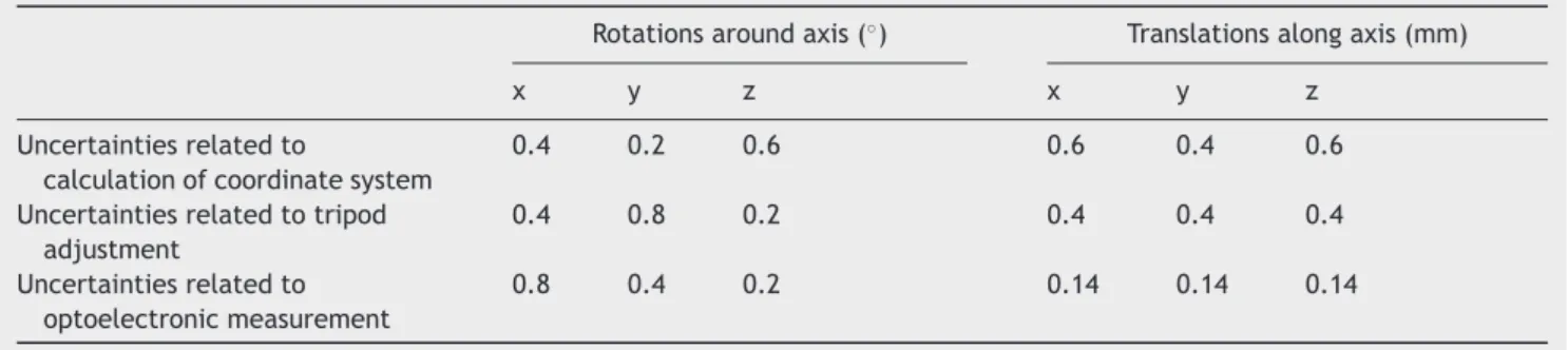
![Table 4 Examples of measurement error estimation in in vitro studies [10] (list not exhaustive).](https://thumb-eu.123doks.com/thumbv2/123doknet/7286701.207959/9.892.460.808.127.329/table-examples-measurement-error-estimation-vitro-studies-exhaustive.webp)
Documents relatifs
We tested a 2D Gaussian-component decomposition using metallicity and radial velocity as discriminating variables.. Radial velocity dispersion as a function of metallicity by bins of
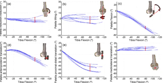
Figure 5 Experimental results: patellar kinematics (rotations and translations) described according to femoral coordinate system within knee flexion—extension cycle....
This study aimed at investigating the effect of four shoulder kinematic chains used to study MWC propulsion on marker reconstruction errors, joint kinematics and
Evaluation of a scapula spinal marker cluster to track the scapula kinematics during manual wheelchair propulsion.. A. Lombart a,b , A. Siegel a,b , C. Villa b , J. Bascou b
If some linguists reject clipping as part of morphology, therefore rejecting its role as a word- formation device, others deem that its study is closely linked to both
These studies displayed the normal tibiofemoral joint kinematics measured using gold standard methods during weight- bearing dynamic activities: walking [1, 2, 7–10], drop landing
To our knowledge, this study is the first considering the effect of changing hip and knee angles on skin and deep fascia surfacic strain fields. Strain field is heterogeneous for
Here, we have discussed three different forward modes for computing gravity anomalies and compared them based on the convergence rates of the obtained gravity field, the execution
