HAL Id: tel-02949575
https://tel.archives-ouvertes.fr/tel-02949575
Submitted on 25 Sep 2020HAL is a multi-disciplinary open access archive for the deposit and dissemination of sci-entific research documents, whether they are pub-lished or not. The documents may come from teaching and research institutions in France or abroad, or from public or private research centers.
L’archive ouverte pluridisciplinaire HAL, est destinée au dépôt et à la diffusion de documents scientifiques de niveau recherche, publiés ou non, émanant des établissements d’enseignement et de recherche français ou étrangers, des laboratoires publics ou privés.
Cristallisation d’hydrates de cyclopentane en présence
de l’eau salée et de dioxyde de carbone pour le
traitement et le dessalement de l’eau
Son Ho Van
To cite this version:
Son Ho Van. Cristallisation d’hydrates de cyclopentane en présence de l’eau salée et de dioxyde de carbone pour le traitement et le dessalement de l’eau. Other. Université de Lyon, 2019. English. �NNT : 2019LYSEM019�. �tel-02949575�
N °d’ordre N NT : 2 0 19LYSEM019
THESE de DOCTORAT DE L’UNIVERSITE DE LYON
opérée au sein de
l’Ecole des Mines de Saint-Etienne Ecole Doctorale N° 488
Sciences, Ingénierie, Santé Spécialité de doctorat : Génie des Procédés
Discipline : DS8 Sciences pour l'ingénieur
Soutenue publiquement le 19/07/2019, par : Son Ho-Van
Cristallisation d'hydrates de cyclopentane en présence de l'eau salée et de
dioxyde de carbone pour le traitement et le dessalement de l'eau
Crystallization of cyclopentane hydrates in presence of brine and
carbon dioxide for water treatment and desalination
Devant le jury composé de :
Christelle GOUTAUDIER Professeure, Université Lyon, Université Claude Bernard Lyon 1, France
Présidente
Beatrice BISCANS Directrice de Recherche CNRS, Laboratoire de Génie Chimique, Toulouse, France
Rapporteure
Praveen LINGA Associate professor, National University of Singapore, Singapour
Rapporteur
Jean-Michel HERRI Professeur, École Nationale Supérieure des Mines de Saint-Étienne, Saint-Étienne, France
Directeur de thèse
Baptiste BOUILLOT Maître de conférences, École Nationale Supérieure des Mines de Saint-Étienne, Saint- Étienne, France
1
List of contents
List of contents ...1 List of figures ...3 List of tables ...4 Acknowledgements ...5 Résumé ...7 Abstract ...8 General Introduction ...9Chapter I. State of the art ... 13
1.1. Clathrate hydrates ... 13
1.1.1. Definition and structure... 13
1.1.2. Phase equilibria of clathrate hydrates... 16
1.1.3. Issues and potential applications of clathrate hydrates... 19
1.2. Cyclopentane hydrates ... 21
1.2.1. Introduction to cyclopentane hydrates ... 22
1.2.2. Thermodynamics of Cyclopentane hydrates ... 23
1.2.3. Mixed CO2+cyclopentane hydrates ... 23
1.3. Clathrate hydrates for desalination... 25
1.4. Case of Cyclopentane hydrates-based desalination... 27
Chapter II. Experimental system for thermodynamics ... 31
2.1. Materials ... 31
2.2. Experimental apparatus... 31
2.2.1. Experimental apparatus for Cyclopentane hydrates thermodynamics study... 31
2.2.2. Experimental apparatus for CP+CO2 hydrates thermodynamics study ... 33
Chapter III. Modeling clathrate hydrates equilibrium ... 35
3.1. Standard freezing point depression (SFPD) approach ... 35
3.2. Hu-Lee-Sum (HLS) correlation ... 36
3.3. Kihara approach ... 37
3.4. Activity-Based Occupancy Correlation (ABOC) approach ... 39
Chapter IV. Thermodynamics results ... 41
4.1. CPH equilibrium results ... 41
4.2. CP/CO2 hydrates equilibrium results ... 43
Chapter V. Cyclopentane hydrates crystallization and morphology study ... 45
2
5.2. Experimental procedure ... 46
5.3. Results ... 47
References ... 50
Chapter VI. Introduction to the papers... 59
6.1. Paper I: Cyclopentane hydrates – a candidate for desalination?... 60
6.2. Paper II: Experimental Measurement and Thermodynamic Modeling of Cyclopentane Hydrates with NaCl, KCl, CaCl2, or NaCl-KCl Present ... 121
6.3. Paper III: Implementing Cyclopentane Hydrates Phase Equilibrium Data and Simulations in Brine Solutions ... 135
6.4. Paper IV: Crystallization mechanisms and rates of Cyclopentane Hydrates formation in Brine ... 147
6.5. Paper V: Morphology of Cyclopentane Hydrates in Saline Water ... 161
6.6. Paper VI: Phase equilibrium investigations of mixed cyclopentane and carbon dioxide hydrates in presence of different salt solutions... 167
Chapter VII. General conclusion and perspectives... 193
3
List of figures
Figure 1: Three main hydrate structures and their constitutive cavities (taken from Sloan and Koh [7])
... 14
Figure 2: Hydrate phase diagrams. (a) CH4+H2O or N2+H2O, (b) Hydrocarbon + H2O with upper quadruple points, (c) Multicomponent natural gas + H2O, (d) Hydrocarbon + H2O with upper quadruple points and inhibitors (taken from [1]) ...17
Figure 3: Solid hydrates obtained from the slugcatcher [2] ...19
Figure 4: Occupation of the large cages (51264) of hydrates sII by CP molecules [30] ...22
Figure 5: A simplified schematic of clathrate hydrates based desalination ...25
Figure 6: Progression in desalination via hydrate formation [53,54,58–63] (adapted from Babu et al [24])...26
Figure 7: Simplified schematic of the apparatus for CPH thermodynamic study [28] ...32
Figure 8: Diagram of experimental set-up for mixed CP+CO2 hydrates thermodynamic study ...34
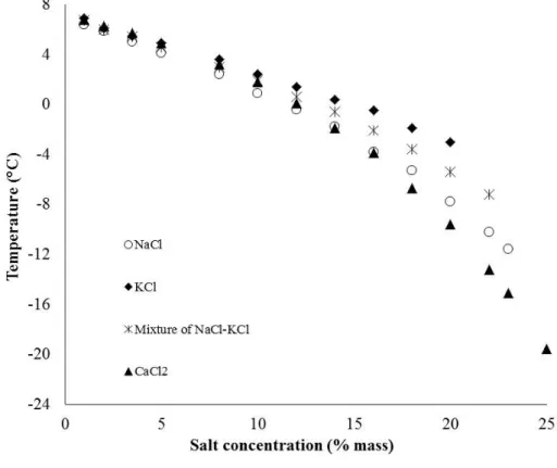
Figure 9: Equilibrium temperature of CPH in the presence of NaCl, KCl, NaCl-KCl, or CaCl2 from experiments ...41
Figure 10: Equilibrium temperature of CPH in the presence of MgCl2, MgCl2-NaCl, MgCl2-NaCl-KCl, or Na2SO4 from experiments ...42
Figure 11: V-LW-LHC-H equilibrium data of CP/CO2 hydrates in pure water and in brine...43
Figure 12: Schematic illustration of the experimental set-up for CPH crystallization mechanism and morphology study [106]...46
Figure 13: Simplified scheme of the CPH crystallization mechanism near the interface in the reactor cell ...47
Figure 14: The mass transfer mechanism of CP, water, and salt during CPH crystallization ...48
4
List of tables
Table 1. Summary of three principle hydrate structures [7] ... 14
Table 2. A list of guest molecules and their hydrate structures [1] ... 15
Table 3: A summary on equilibrium data of mixed CP+CO2 hydrates... 24
Table 4: Purity of initial material used ... 31
Table 5: Thermodynamic data used for Kihara parameters optimization in binary CP/CO2 hydrates.. 38
Table 6: Optimized Kihara parameters for CP in two different hydrates systems... 39
Table 7: Average deviation (°C) of different approaches for simulating CPH equilibrium ... 43
Table 8: Average deviation between simulations and measurements of CP/CO2 hydrates equilibrium. ... 44
5
Acknowledgements
First of all, I would like to thank my supervisor Professor Jean-Michel HERRI and my co- supervisor Dr. Baptiste BOUILLOT for the constant support during my four-year PhD course, for their patience, gentleness, inspiration, and immense knowledge. This was my great honor to work with them since I have gained so much from them in the hydrate field. They both have been very supportive sine the very first days when I and my family arrived in France and started working on the PhD project in 2015.
My thanks also goes to Professor Daniel GARCIA and Professor Ana CAMEIRAO for their discussions and valuable ideas in the experiments and in the manuscripts, and for being co- authors in my some publications.
I am grateful to Dr. Jérôme DOUZET and Dr. Saheb MAGHSOODLOO BABAKHANI for their help and support in almost experiments on thermodynamic and crystallization in the laboratory in Spin center. They are always available and willing to share and discuss with me to solve problems.
I sincerely thank Dr. BISCANS and Dr. Praveen LINGA who have accepted the difficult task of being referees of this work. I also thank Professor Christelle GOUTAUDIER for giving me the pleasure and honor of chairing my defense.
In addition, I would like to thank to my colleagues, technicians and personnel in SPIN center: Trung-Kien PHAM, Thang LE, Du LE-QUANG, Vinicius RODRIGUES DE ALMEIDA VENICIUS, Carlos LANGE-BASSANI, Fabien CHAUVY, Jacques MOUTTE, Frédéric GALLICE, Hubert FAURE, Jean-Pierre POYET, Marc ROUVIERE, Jérôme MANCUSO, Andrée-Aimée TOUCAS, Marie-Claude BARTHOLIN, Céline BACHEKOUR, Joëlle VERNEY, Florence DUJARDIN for their help in science, informatics, and administrations.
I would like to sincerely acknowledge the Vietnam International Education Development, Ministry of Education and Training, for the financial support through the PhD (scholarship program 911). I would like to thank also Hanoi University of Mining and Geology for allowing and supporting me to study PhD in France.
Lastly, I would like to thank my beloved family: my mother Thi-Lieu NGUYEN, my father Dai HO, my wife Thi-Duc TRAN, my sons Minh-An HO, Anh-Minh HO, and my sisters Thi- Luong HO, Thi-Huong HO, my brother Duc-Cuong HO for all their love, and encouragement.
7
Résumé
Ces travaux de thèse ont pour but de compléter les connaissances actuelles sur la cristallisation des hydrates de cyclopentane dans les domaines de la désalinisation et du traitement de l’eau. Ils débutent donc par une étude bibliographique la plus exhaustive possible incluant les aspects thermodynamiques, cinétiques et morphologiques des hydrates de cyclopentane dans les nouveaux procédés de désalinisation par cristallisation. Les principaux verrous à lever sont mis en lumière, tout en apportant quelques suggestions pour le développement à long terme de ce type de technologie. Une conclusion montre que les hydrates de cyclopentane pourraient être de bons candidats, en plus d’autres additifs, pour des applications dans le domaine de la désalinisation.
Ensuite, d’importantes nouvelles données d’équilibre des hydrates de cyclopentane dans de l’eau en présence de sels ont été obtenues (NaCl, KCl, NaCl-KCl, CaCl2, MgCl2, MgCl2- NaCl, MgCl2-NaCl-KCl, ou Na2SO4). Les résultats ont été modélisés selon quatre approches. La première est basée selon l’équation SFPD (standard freezing point depression). La seconde sur la nouvelle corrélation Hu-Lee-Sum (HLS). Les deux autres sur le modèles de van der Waals et de Platteeuw, soit en utilisant le potentiel d’interaction de Kihara, soit avec une simple corrélation entre le coefficient d’activité de l’eau et la stœchiométrie de l’hydrate. Cette dernière simule des résultats avec une précision de 0,2°C. Lors de ces expériences, en plus de la cristallisation des hydrates, la précipitation des sels a été observée, ce qui offre la possibilité de récupérer ces derniers sous forme cristallisée, en plus du traitement de l’eau.
En parallèle, un travail plus fondamental a été mené sur les mécanismes de cristallisation, les vitesses de croissance des cristaux et la morphologie des hydrates de cyclopentane dans l’eau pure et en présence de sels. Une petite cellule refroidie et non agitée, placée sous un microscope a été utilisée à différentes conditions expérimentales (sous-refroidissements et concentrations en sels).
Pour terminer, un additif gazeux a été ajouté à l’étude : le dioxide de carbone. Des points d’équilibre d’hydrates mixtes de cyclopentane+CO2 ont donc été obtenus expérimentalement, notamment en présence de sels (KCl, NaCl, et NaCl-KCl). Ces résultats sont nécessaires pour le développement de procédés pouvant combiner la désalinisation au captage du CO2. Pour cela, une méthode isochore a été appliquée dans un réacteur de type batch. Un outil de modélisation thermodynamique basé sur l’approche de van der Waals a été utilisé pour simuler ces équilibres.
8
Abstract
This thesis is an effort to fulfill the gap in the literature on cyclopentane (CP) hydrates for desalination and water treatment applications. Accordingly, it begins with a comprehensive review on Cyclopentane hydrates for hydrate-based treatment processes. This literature work covers all aspects of thermodynamics, kinetics, morphology, hydrate phase properties, and the recent use of Cyclopentane hydrates in desalting process that require to develop an advanced and sustainable technique via hydrate crystallization. Some challenges to overcome in the long term, and critical perspective suggestions are also addressed. A short conclusion is that cyclopentane hydrates, with additives, could be a candidate for desalination.
Then, new thermodynamic equilibrium of cyclopentane hydrates are provided, in pure water and in presence of different electrolyte systems including NaCl, KCl, NaCl-KCl, CaCl2, MgCl2, MgCl2-NaCl, MgCl2-NaCl-KCl, or Na2SO4. Results have been modelled with four approaches. The first is based on the standard freezing point depression (SFPD) equation. The second is based on Hu-Lee-Sum (HLS) correlation. The two others are based on van de Waals and Platteeuw model: either with the use of Kihara potential, or a simple correlation between water activity and the hydrate stoichiometry. The last one simulates the experimental results within 0.2°C uncertainty. Moreover, salt crystallization has been achieved, opening the possibility for product recovery with hydrate crystallization.
Besides, the crystallization mechanisms, crystals growth rates, and morphology of cyclopentane hydrates crystals in pure water and in the presence of various salts (NaCl, NaCl- MgCl2, NaCl-KCl-MgCl2, or Na2SO4) have also been studied. A non-agitated reactor cell, connected to a microscope, has been employed, as well as different experimental conditions (subcooling and salinity).
Finally, equilibrium data of binary CP+CO2 hydrates in pure water and in the presence of three electrolyte solutions (KCl, NaCl, and NaCl-KCl) are provided. Such results are interesting in the development of combined hydrate-based desalination and CO2 capture. Accordingly, an isochoric method is applied in a batch-mode reactor. A thermodynamic simulation tool based on van der Waals and Platteeuw approach and Kihara potential approach is utilized to reproduce equilibrium.
Keywords: Cyclopentane hydrates, Binary Cyclopentane and Carbon dioxide hydrates, thermodynamics, crystallization, water treatment, desalination.
9
General Introduction
This thesis takes the form of an articles collection, after having properly introduced the state of the art, the experimental apparatus and procedures, and the main results. The articles are listed as follows:
1. Paper I: Cyclopentane hydrates – a candidate for desalination? This article presents a systematic review of cyclopentane hydrate for desalination applications
2. Paper II: Experimental Measurement and Thermodynamic Modeling of Cyclopentane Hydrates with NaCl, KCl, CaCl2, or NaCl-KCl Present. This first article of the thermodynamic study provides equilibrium data in presence of salts, and suggests the use of three thermodynamic approaches to model the results.
3. Paper III: Implementing Cyclopentane Hydrates Phase Equilibrium Data and Simulations in Brine Solutions. This second article of the thermodynamic study expands the system to other salts, and introduces the use of another approach: the Hu- Lee-Sum correlation.
4. Paper IV: Crystallization mechanisms and rates of Cyclopentane Hydrates formation in Brine. This article present the layer growth phenomenology and calculate the growth rates of cyclopentane hydrate in pure water and in the presence of salts
5. Paper V: Morphology of Cyclopentane Hydrates in Saline Water. This next article focuses on the morphology of cyclopentane hydrates. The effects of salt and subcooling on the geometric shape and the size of individual hydrate crystals are explored.
6. Paper VI: Phase equilibrium measurements and modelling of mixed cyclopentane and carbon dioxide hydrates in presence of different salt solutions. This final article on thermodynamics introduces another guest molecule: carbon dioxide. This new guest is interesting to couple water treatment to carbon capture process.
More details on these articles are provided in the following:
Our first effort is to perform a comprehensive review on CPH for salt removal application. All published studies available in the literature related to the thermodynamic, kinetic, hydrate phase properties, morphology, and the advancements of CPH in desalination are considered. In this work, we compare the desalting process via CPH crystallization to other traditional methods like distillation, freezing, and reverse osmosis. Our findings suggest that beside some challenges yet to overcome, CPH is a potential applicant for desalination.
10
After, the thermodynamic of CPH formation in the presence of salts (NaCl, KCl, CaCl2, or NaCl-KCl) is investigated. Two procedures are applied to determine equilibrium. The first is at high dissociation rate, for approximation. The second is at a much lower dissociation rate, for more reliable data. Our measurements show that the equilibrium temperatures dropped considerably with increasing of salinity for all tested electrolytes. In addition, three thermodynamic models are developed to reproduce the equilibrium data. The first is based on the standard freezing point depression (SFPD) equation; the two others are based on van de Waals and Platteuw model. While one approach used optimized Kihara parameters, the last introduced a novel correlation between the occupancy factor and water activity. Modelling results indicate that all models have good capacities of predicting equilibrium. The last method, the activity-based occupancy correlation (ABOC), is the most recommended method to achieve accurate equilibrium.
Our next effort extends CPH equilibrium to four more common electrolyte solutions: Na2SO4, MgCl2, MgCl2-NaCl, or MgCl2-NaCl-KCl at various salt concentrations. Of course, the two procedures (quick and slow) were again applied as before. Then, four thermodynamic approaches SFPD, Hu-Lee-Sum (HLS) correlation from Hu et al (2017,2018), and the two van der Waals and Platteuw-based (Kihara and ABOC methods) are compared to this new data. Again, simulation results illustrate that all four approaches reproduce adequately the CPH equilibrium temperature. Nonetheless, the ABOC method is confirmed to be the best method to achieve rapid and reliable equilibrium data of CPH in brine, whatever the salts involved.
Apart from thermodynamics, crystallization mechanism has been also investigated, such as hydrate layer growth rates, and morphology of CPH, hydrate layer growth rates, and morphology of CPH from pure water and brine. Different brine solutions of Na2SO4, NaCl, NaCl-MgCl2, or NaCl-KCl-MgCl2 at different concentrations (3.5% and 5% mass) were considered. Three different driving forces (subcooling of 2.5°C, 3.5°C, and 4.3°C) were considered. For that purpose, a small non-mixing batch-type vessel (inner volume ≈ 1.23 ml) connected to a microscopy was employed. We detected the primary formation of some individual crystals at the liquid-liquid interface vicinity. The hydrate layer crystallization began with a rapid nucleation at this interface. Then, the layer propagated mostly into the CP phase. Hence, we suggested that the water phase transports advectively through the presumably porous water-wet hydrate layer. Moreover, the hydrate layer growth rates
11
augmented with increasing of subcooling, with all salts considered. The growth rates also dropped with time due to the increased thickness of the hydrate layer.
In addition, our observations indicates that the CPH crystals morphology is approximately comparable at the same subcooling, while the size of the individual crystals drops significantly with increasing of subcooling, regardless the type of salts and their concentrations. Accordingly, subcooling might be served as a criterion to classification the morphology and the size of individual hydrate crystals.
Our last effort is to investigate thermodynamics of Cyclopentane (CP) + CO2 binary hydrates in the presence of salt. That is crucial addition for hydrate-based desalination, especially when CO2 capture process is involved. In this effort, new four-phase equilibrium measurements (V- LW-LHC-H) for CP/CO2 binary hydrates in the presence of NaCl, KCl and a mixture of NaCl- KCl was obtained. An isochoric procedure was applied in a batch-type reactor. Then, the van de Waals model was utilized to model equilibrium. Expectedly, our results illustrate that the mixed CP/CO2 hydrates are formed under milder conditions compared to the pure CO2 hydrate. The presence of electrolytes in solution, unsurprisingly strongly inhibits the CP/CO2 hydrates formation. Moreover, NaCl present a stronger influence than KCl, for the same salt concentrations. In addition, two different dissociation rates have been observed, showing a probable co-existence of single CO2 SI hydrate and mixed CP/CO2 SII hydrates. Then, the van de Waals approach is applied to describe the equilibrium. Simulation results indicate that this approach is capable of regenerating CP/CO2 dissociation conditions with an average deviation than 0.4K for all tested brine systems.
In conclusion, this study helps at providing a reliable reference, or extensive data set, for the development of hydrate-based promising techniques, such as water treatment via CPH crystallization. Valuable thermodynamics, as well as kinetics, data are furnished. Hopefully, this work will provide an index for the research in this field.
13
Chapter I. State of the art
1.1. Clathrate hydrates
1.1.1. Definition and structure
Clathrate hydrates, are ice-like crystalline solids composed of water and guest molecules [1]. Water molecules are connected through hydrogen bonding system and form cages that enclose different guest molecules. Guest compounds can be small gas molecules like H2, CO2, N2, CH4, C2H6 C3H8 or larger molecules like Cyclopentane, Tetrahydrofuran (THF), or Tetra- n-butyl ammonium bromide (TBAB) etc. Note that, when gaseous molecules are guest in the structure, Clathrate hydrates are also called ‘’Gas Hydrates’’. Because all cages are not occupied by guest molecules, clathrate hydrates are “nonstoichiometric” compounds [1]. Hydrate formation is not a chemical reaction, but only a physical phase-change reaction. Low temperatures and high pressures are usually favorable conditions for their formation.
Three principal polymorphs of clathrate hydrates are well-known: structure I (sI), structure II (sII), and structure H (sH). Each one contains of a certain quantity of different cavities formed by water molecules through a hydrogen bonding system.
Figure 1 and Table 1 illustrate the three main hydrate structures. In structure I (sI), each unit cell has 8 cavities including of two pentagonal dodecahedron (512) cavities and six tetrakaidecahedron (51262) cavities. The sI unit crystal fits a cubic 12 Å on a side [2]. Small guest molecules having diameters from 4.2 to 6 Å such as CH4, C2H6, CO2, or H2S can form this hydrate sI. Indeed, hydrate sI can be found mostly in nature because CH4 is the main constituent of natural gas. Potential reserves of natural gas hydrated located offshore and on land was reported to be over 1.5×10¹⁶ m3 [3].
Structure II and H hydrates can accommodate larger guest molecules, such as C3H8 or iso- butane (6Å <diameters <7 Å) for sII or mixtures of CH4 and Neohexane or Cycloheptane (7Å <diameters <9 Å) for sH. Interestingly, smaller molecules with diameters inferior to 4.2 Å, such as Nitrogen or Hydrogen, can also form structure II as single and multiple guests [1]. In sII hydrates, each unit cell contains sixteen small pentagonal dodecahedron (512) cavities and eight large hexakaidecahedron (51264) cavities. Structure II hydrates are usually found in oil and gas operations and processes.
14
In the case of sH, each unit cell presents three small pentagonal dodecahedron (51262) cavities, two medium dodecahedron (435663) cavities, and one large icosahedron (51268) cavity. Structure H hydrates are rarely found in non-natural (gas storage [4]), or in natural processes (Gulf of Mexico continental slop [5]) [2,6].
Cavity types Hydrate structures Guest molecules
Figure 1: Three main hydrate structures and their constitutive cavities (taken from Sloan and
Koh [7])
Table 1. Summary of three principle hydrate structures [7]
Hydrate structures sI sII sH
Cavity Small Large Small Large Small Medium Large
Description 512 51262 512 51264 512 435663 51268 Number of cavities per unit
cell 2 6 16 8 3 2 1
Average cavity radius (Å) 3.95 4.33 3.91 4.73 3.91b 4.06b 5.71b
Coordination number a 20 24 20 28 20 20 36
Number of waters per unit
cell 46 136 34
a
15
Typically, in all three hydrate structures, each cage hosts only one guest molecule. Nevertheless, under very high pressure, the clathrate cages can be multiply occupied with several abnormally small guests, like hydrogen, or inert gases such as nitrogen. For instance, Mao et al [8] indicated that, at pressures from 180 to 200 MPa, the clathrate cavities can be multiply occupied, with a cluster of two hydrogen molecules in the small cavities and four in the large cavities.
Note that, when all cavities are fully occupied by guest molecules, the hydration number (number of water molecule/number of guest molecules) for Structure I, Structure II, and H hydrates is ideally 24/3, 17/3, and 17/3, respectively [1] .
Several examples of hydrate formers with their hydrate structures can be found in Table 2. Of course, the kind of hydrate structure depends on the type and the size of guest molecules. In addition, some help gases like Xe, CH4 are utilized to stabilized hydrate structure since they occupy the small empty cages.
Table 2. A list of guest molecules and their hydrate structures [1].
Guest molecules Hydrate structures
Ar II H2 II N2 II CO2 I CH4 I C2H6 I C3H8 II Cyclopentane II
Benzene with help gases Xe II
CH2ClCH2Cl with help gases air II 2-Methylbutane with help gases Xe H Cycloheptane with help gases CH4 H Methylcyclopentane with help gases Xe, CH4 H
16
1.1.2. Phase equilibria of clathrate hydrates
Usually, Clathrate hydrates phase equilibria are determined in terms of the following variables: (1) pressure, (2) temperature, and (3) phases’ compositions. Other variables like volume or density, phase amount may be mathematically calculated by phase equilibria and validated by some measurements that are challenging to achieve and hence not common [1].
Let us remind the Gibbs’ Phase rule, providing the number of degree of freedom, in terms of intensive parameters, for a system:
F=2+C-P’ (1)
Where F is the number of intensive variables needed to specify the system, C is the number of components in the system and P’ is the number of phases in the system.
Temperature (T), pressure (P), and phase mole fractions (hydrate, liquid, or vapor phases) are intensive variables, measurable, and hence independent of the phase amount. However, masses or volumes are extensive variables, and cannot be considered in the Gibbs’ Phase rule.
In the case of Clathrate hydrates, there are at least two compounds: water, and a guest molecule. An addition of guest molecules increases the number of degree of freedom. The number of phases depends on the kind of molecules, and the operating conditions. Let us take an example: methane hydrates, or nitrogen hydrates. Phase diagrams of these, at conditions inside and outside the hydrate region, are illustrated in Figure 2a. Note that Pressure and Temperature are the usual two variables considered, over composition. In the figure, I, LW, H, V, and LHC correspond to ice, water liquid, hydrate, vapor, and hydrocarbon liquid, respectively. Q1 is the quadruple point, defining as the starting point for four three-phase lines. More details on all these three-phase lines are described as follows:
17
Figure 2: Hydrate phase diagrams. (a) CH4+H2O or N2+H2O, (b) Hydrocarbon + H2O with upper quadruple points, (c) Multicomponent natural gas + H2O, (d) Hydrocarbon + H2O with
upper quadruple points and inhibitors (taken from [1])
The LW-H-V line includes thermodynamic conditions of P-T that are crucial in natural gas systems.
The I-H-V line has a lower P-T slope than the LW-H-V line. Data in the region below 273 K are limited because of ice formation issues.
The I-LW-H line goes up vertically from the Q1 point. Because phases are incompressible in this region, a huge pressure change is hence required for a minor temperature change.
18
The I-LW-V line links the quadruple point to the water triple point (I-LW-VW) (273.16 K, 0.62 kPa). This outlines the transition between water and ice without hydrate crystallization. The I-LW-V line is nearly vertical below Q1 to 0.62kPa because Q1 is about 273 K for all natural gas systems.
Figure 2b illustrates a second quadruple point (Q2=LW-H-V-LHC) formed at the intersection of LW-V-LHC line with the LW-H-V line. In this system, the hydrate area is bounded by three lines: I-H-V below Q1, LW-H-V between Q1 and Q2, LW-H-LHC above Q2. This means no hydrate can form at conditions (T, P) to the right of the area bounded by these three lines. Since the LW-H-LHC line rises vertically, the upper point Q2 is close to the maximum temperature of hydrate crystallization.
Indeed, the lower quadruple point Q1 represents the transition of liquid water to ice and hydrate crystallization from ice and vapor. The upper quadruple point Q2 signifies the upper temperature limit for hydrate crystallization. Methane and nitrogen are known as hydrate formers with no upper quadruple point because of their low vapor pressure at the critical temperature, meaning no temperature limit for hydrate formation.
Multicomponent natural gas hydrate phase diagram is detailed in Figure 2c. Note that, the LW- H-V line is applied for a hydrocarbon mixture, not for pure CH4. The quadruple point Q2 is at the intersection of the LW-H-V line at 273 K at a pressure lower than that for CH4.
Interestingly, the LW-V-LHC line becomes a region, labeled CFK in the figure. The reason is that no single hydrocarbon is present and that a combination of hydrocarbon + water vapor pressure generates a phase equilibrium envelope. Accordingly, the upper quadruple point Q2 changes into a line (KC). The lower point K is created by the intersection of the phase envelope ECFKL with the LW-H-V line. Whilst the upper point C is determined via a vapor- liquid equilibrium calculation.
The effects of inhibitors such as salts, alcohols, or glycols on thermodynamic equilibrium of hydrocarbon + water system are presented in Figure 2d. Simply, the hydrate bounding area (to the left of AQ1Q2B line) is illustrated. As seen in the figure, the line Q1Q2B is shifted approximately parallel to the left with inhibitor present. The ice formation temperature is also decreased. Accordingly, the intersection point between the LW-H-V line and the I-H-V line is at lower location (labeled Q1’ and Q2’ for 10 % and 20 % mass methanol).
19
Obviously, each inhibitor has a different effect on the hydrate equilibrium. Numerous inhibitors have been also thermodynamically tested in the hydrate formation like glycol (EG or MEG) and salts. However, ethanol is considered to be the most economical inhibitor on a mass basis.
When hydrate formers are liquid such as Tetra-n-butyl ammonium bromide (TBAB), Tetrahydrofuran, Cyclopentene, or cyclopentane, no pressure is usually needed to form clathrates. The hydrate phase diagram is hence expected to be simpler compared to that with gas hydrates system. This fact brings potential opportunities for several hydrate-based applications in water treatment, air-conditioning, or cold thermal energy because no high pressure devices are required. Cyclopentane is one of these hydrate guests which have gained increasing attention in water treatment, or water decontamination applications in the last decades. Note that thermodynamic modelling will be presented later in the chapter III.
1.1.3. Issues and potential applications of clathrate hydrates
Clathrate hydrates have been extensively investigated in the last decades. In fact, hydrate formation is a common issue in the oil and gas industry. Clathrate hydrates are solid and non- flowing crystalline structure. Furthermore, oil and gas wells normally generate water along with gases or hydrocarbon. When they are in the hydrate zone, water and gases or hydrocarbon can form solid hydrates and plug pipelines, causing equipment and environment damages (see Figure 3) [7]. Therefore, safety is probably a key reason for understanding hydrate blockages [2].
20
Hydrate formation issue in the pipeline can be prevented by both physical method (controlling pressure, temperature, and water removal) and chemical method (Thermodynamic Hydrate Inhibitor – THIs; Low Dosage Hydrate Inhibitors (LDHIs); Kinetic Inhibitor or Anti- Agglomerants – AAs [1]. Indeed, chemical methods are more widely utilized than physical methods as their low cost. Among the chemical techniques, LDHIs are recently considered to be an advanced and sustainable technology in flow assurance.
Besides, clathrate hydrates have also many potential applications in both industry and environment because of their several key physical and chemical properties [7]. Gas hydrates can be used for gas storage [9–11], hydrogen storage [12], carbon dioxide capture [13–15], gas separation [16,17], air-conditioning and cold thermal energy [18–20], and desalination [21–24]. Of course, more experimental studies are still required to optimize the innovative and sustainable hydrate-based applications. More details of these applications are provided in the following:
It was found that approximate 70% of the gas reserve is too far from a current pipeline system or too insignificant to justify a liquefaction system [7]. Thus, transport of natural gas by pipeline system or LNG is very costly. In addition, this technique is dangerous due to natural gas is super inflammable and explosive at high pressures. Transport gas in hydrate form technology could be cheaper and safer than traditional methods. Indeed, one cubic meter of clathrate hydrates can accommodate approximate 180 Nm3 of CH4 [4]. In addition, because no very low temperatures are required (0.1 MPa and 193 K without promotor, 0.1 MPa and 277.2 K with promotor [25]), natural gas storage in hydrate form is cheaper than in LNG form (0.20 MPa and 113.2 K [25]).
Furthermore, as hydrogen is considered as a next generation clean energy, investigations on hydrogen storage have been performed intensively in the last decades. Hydrate-based storage technology is safer and probably more economically feasible than other traditional methods [7,26]. An up-to-date systematic review and upcoming instructions for hydrogen storage in gas hydrate form can be found in the work of Veluswamy et al [12].
Carbon dioxide capture and gas separation are promising applications of clathrate hydrates. The concept of using clathrates for these applications is based on the fact that gas molecules are absorbed selectively in hydrate cavities depending on their shape and size during hydrate crystallization. Accordingly, this property of clathrates could be applied to separate [16,17] or storage [13–15] the desired guest molecules from their mixtures. The advantages of these
21
hydrate-based technologies are milder operating conditions and hence lower energy requirements are required.
Currently, numerous techniques for thermal energy storage have been developed for air- conditioning. Thermal energy storage systems via the liquid-solid phase change of water are now usually employed for both industrial and domestic air-conditioning [27]. However, this technique requires the coiled tubes on which the ice layers grow to be reserved at low temperatures from -4 to -10oC, limiting factor of the coefficient or performance (COP) of the refrigerator. Accordingly, a new thermal energy storing material that undergoes a phase change at a temperature close to the desired temperature (7 to 12oC) for air cooling is required. For instance, TBAB (tetra-n-butylammonium bromide) can form hydrates at temperatures between 5 and 12oC [27,28]. This new cooling storage material is hence well- suited to air-conditioning. Consequently, the use of hydrate (TBAB) for air conditioning has been investigated [18,19] and commercialized [20]. This hydrate-based technique is considered to be a sustainable energy-saving technology.
Lastly, desalting seawater is also another promising application of clathrate hydrates [7,29]. The concept of this technique is simply based on the fact that, during hydrate crystallization, salts are excluded and remain in the liquid solution. Eventuelly, they can even precipitate in the concentrated solution. Afterward, salts can be removed by a physical separation technique. Finally, pure water can be achieved after dissociation of the hydrates. Note that this approach can also be used to treat wastewater, or recover dissolved value added products.
In order to optimize these hydrate based technology, more studies are still necessary including thermodynamics, kinetics, crystallization mechanisms, morphology, hydrate physical and chemical properties, hydrate composition, volume and storage capacity, consistent simulation tools to predict hydrate equilibrium.
1.2. Cyclopentane hydrates
This section presents a brief presentation about cyclopentane hydrates including hydrate structure, thermodynamic of pure cyclopentane hydrates and mixed CP-CO2 hydrates which are crucial in hydrate-based applications via cyclopentane hydrate crystallization.
22
1.2.1. Introduction to cyclopentane hydrates
Cyclopentane forms hydrates sII with water at a temperature less than approximately 7.1°C [27] without a help of a high pressure equipment, according the following equation:
C5H10 + 17 H2O = C5H10.17H2O (CPH) (2)
In this pure sII hydrates, due to its size, cyclopentane only occupies the large 51264 cages, while leaving the small 512 cages empty, as illustrated in Figure 4.
Figure 4: Occupation of the large cages (51264) of hydrates sII by CP molecules [30] In the presence of a gas or several gases, a mixed hydrate of CP+H2O+gas can be formed. In this mixed hydrates, large cages (51264) of the structure are occupied by the CP, while small cages (512) are occupied by small “gas’’ molecules, like CH4, CO2, or N2.
Unique structural features and physical and chemical properties of CPH have gained much attention of scientists. Indeed, their work focused on four distinct areas: the use of CPH as a thermodynamic promoter to lower the pressure of formation of mixed hydrates including gas [31,32]; the use of CPH as a "kinetic" promoter to improve the kinetics of capture gases, the use of CPH in hydrate slurries, and the use of CPH in water treatment.
In order to develop the use of CPH, phase equilibrium data of CPH are crucial. Thus, in the next subsection, the thermodynamic of CPH is presented.
23
1.2.2. Thermodynamics of Cyclopentane hydrates
At normal atmospheric conditions, according to literature, the equilibrium temperature of CPH in pure water rage from 6.3°C to 7.7°C. Several techniques were applied to determine the equilibrium temperatures of CPH like Differential Scanning Calorimetry (DSC) [27,33– 36], or polythermal method [37–41]. Among these techniques, the polythermal method (at low heating rate) and DSC methods provide consistent and reliable equilibrium data for CPH (around 7.1°C). However, polythermal method is sometimes used with a high heating rate (room temperature) [40–42]. In this case, the induced quick dissociation usually misses the right equilibrium temperature, because of the high melting rate. Accordingly, the value of equilibrium temperature obtained by the quick technique (approximately 7.8°C) is usually higher than the supposed genuine value. Moreover, in the presence of surfactants, the equilibrium temperature can be reduced [35,36,43,44]. This is because surfactants modify the interfacial tension force between cyclopentane and water. The hydrate formation is hence affected.
Under vacuum conditions, Fan et al. [90] reported the CPH equilibrium data with the range of temperature of 0.21-7.07°C and the pressure of 6.9-19.8 kPa. Moreover, at high pressure (2.55-12.55 Mpa), Trueba et al. [94] reported hydrate (H) – aqueous liquid (LW) – cyclopentane-rich liquid (La) phase equilibrium data. Their results show that the CPH equilibrium temperatures (range from 6.75°C to 6.88°C) are nearly constant with the increase of pressure.
In presence of common electrolytes, CPH equilibria have not been comprehensively investigated in the last past [35–37,39,40,45]. In these studies only NaCl at various salt concentrations is considered. Two main experimental procedures were applied to determine the hydrate dissociation temperatures: polythermal method [37,39,40,45], and DSC [35–37]. Again, the polythermal method at low heating rate and DSC are capable of providing the accurate equilibrium data
1.2.3. Mixed CO2+cyclopentane hydrates
Mixed CP+CO2 hydrates form structure II. As explained before, CP molecules occupy large cavities while CO2 molecules occupy small cavities. However, although CP usually fill most of the larges cages, note that CO2 molecules do not necessary fill all small cages. This will be supported later in thermodynamic modelling part of the experiments (section 6.6). CP-CO2
24
binary could be a potential candidate for both desalination [46] and carbon capture [15] applications. Of course, in order to develop this combined application, equilibrium data of mixed CP+ CO2 are needed.
A summary of all studies in the open literature on equilibria of mixed CP+CO2 is presented in Table 3. In these mentioned studies, an isochoric procedure was applied to determine the equilibria. In pure water, numerous hydrate formation conditions ranging from 275.5 K to 292.60 K and from 0.08 Mpa to 4.88 Mpa were reported [15,32,47–50].
Obviously, equilibrium data in brine are required when attempting to apply mixed CP+CO2 hydrates for desalination. Cha and Seol [51] investigated upper temperature limit of CO2 hydrate formation in the presence of CP and simulated produced water (8.95 wt% salinity) at isobaric condition (3.1 MPa). They witnessed that the upper temperature limit for CO2 hydrate is -2C, while for mixed CP-CO2 hydrate is 16°C. Zheng et al. [46] measured equilibrium data of CP-CO2 hydrates in the presence of 3 wt% NaCl. Their experiments were carried out with different molar ratios of CP/water. Results indicate that the increase in CP quantity led to a significant drop in equilibrium pressure. In addition, they reported the optimal molar ratio of CP is 0.01 for CO2 hydrate-based desalination. Zhang et al. [52] studied on the phase equilibrium of CO2-CP in the presence of NaCl under a wide range of salt concentrations (0, 3.5, 7.0, 10.0, 15, 25% mass). Interestingly, their results show that CP reduces the equilibrium pressure and improves the salt removal efficiency.
Table 3: A summary on equilibrium data of mixed CP+CO2 hydrates
Aqueous solution Temperature range (K) Pressure range (Mpa) Citation
Pure water 280.16 – 292.60 0.08 – 4.88 [47] Pure water 284.6 – 291.6 0.49 – 2.58 [48] Pure water 275.5 – 285.2 0.42 – 0.59 [15] Pure water 284.3 – 291.8 0.35 – 2.52 [50] Pure water 281.55 – 290.25 0.15 – 1.92 [49] Pure water 283.5– 287.5 0.761– 1.130 [32]
Simulated produced water: 8.95 % mass 280.15 – 289.15 3.1 (isobaric) [51]
NaCl: 3.0% mass 271.89 – 292.21 0.55 – 3.59 [46]
25
Seawater
...
1.3. Clathrate hydrates for desalination
The use of clathrate hydrates for desalting is an inspiring potential hydrate application, since salts are left out from clathrate hydrates crystallization. The concept of desalination via clathrate hydrate is illustrated in Figure 5.
Q Q
Hydrate ... Hydrate r Fresh water formation dissociation '"---
.JFigure 5: A simplified schematic of clathrate hydrates based desalination
This process increases the sait concentration in the aqueous solution. Moreover, hydrate phase can be removed by a physical separation process and then can be dissociated at normal room conditions. Upon dissociation process, fresh water and guest molecules can be released from clathrate crystals. Guest molecules can then be recycled (CP) or stored (C02).
Indeed, the utilization of clathrate hydrate for sait removing process was first explored in 1940s [53]. After, in the 1960s and 1970s, major researches and irnprovements on this process were performed [54-57]. A summary on the progress of desalination via hydrate formation is schematically demonstrated in Figure 6.
As shown in Figure 6, a remarkable progression on clathrate hydrate-based desalination was made. However, this technique is still not commercial ready since some challenges
conceming the cost and the purification level of produced fresh water have not been overcome yet. Varied guest molecules were tested for this technique such as propane [58,59,63,64], carbon dioxide [22,62,64-69], refrigerant [23,59,60,70,71], or methane
[72,73]. lndeed, methane and C02 are identified as greenhouse gases, thus these gases can bring risks into our environment when they are accidentally released. Refrigerants are ozone depletion compounds. They are hence restricted by current environmental regulations and are
no longer practical candidates for a hydrate desalination process, despite their ease of use [61].
26 Two pilot plants were built utilizing R12 and propane hydrates One pilot plant was built using R141b hydrates r
"
Proposed hydrate- based desalination Used propane hydarte: Mathematic approach Propos ed hydrate former selection criteria Used HFC-32, R152a, R141b hydrates: Kinet ic study '- ./Parker et al Knox et al Bardhun et al Koppers Co McCormack Bradshaw Park et Babu et al
1942 1961 1961 1964 et al 1998 et al 2008 2011 2014 A new apparatus producing C02 hydrate pellets was developed New approach using LNG cold energy
Figure 6: Progression in desalination via hydrate formation [53,54,58-63] (adapted from Babu et al [24])
Recently, more than 20 key inventions made over the world to desalination by using clathrate hydrates were detailed according the review work of Babu et al [24]. These efforts focused
mainly on the improving the hydrate crystallization kinetics, as well as separating sait
entrapped between hydrate particles . In order to reduce the induction time, some techniques were proposed such as the use of ultrasonic energy, or micro-bubbles, or localized super- cooling by depressurizing liquid propane. Furthermore, secondary purification treatments
such as washing were also employed to remove sait entrapped on the hydrate crystals surface.
Unfortunately, this step leads a decrease in the overall water recovery of the desalination. Another effort was the use refrigerants such as CFC in order to reduce the total operating cost due to it can form hydrate with water at atmospheric pressure. However, as aforementioned, CFC is considered as a toxic and damageable to the environment. The use of CFC for
desalination application is hence not encouraged.
Lately, He et al.[29] suggested a new hydrate based desalination system using Liquefied Natural Gas (LNG) cold energy. Compared to multi-stage flash distillation (MSF), reverse osmosis (RO), and freezing desalination processes, this technology can be attractive since
LNG cold energy replaces the external refrigeration cycle, and hence reduces the specific
27
source of LNG cold energy. High-pressure reactor is also needed because propane is utilized to form hydrate.
Obviously, before hydrate desalination becomes a practical commercial technology, the vital issues of controlled hydrate nucleation, formation rate, phase properties, as well as the amount of entrapped salt, and its removal efficiency must be thoroughly understood and optimized [61].
1.4. Case of Cyclopentane hydrates-based desalination
Gas hydrate-based desalination is costly when a gas is employed as a hydrate former. Cyclopentane is considered to be a promising replacement, or additive, of the gas molecules. Because CPH crystallization can take place at atmospheric pressure, the energy requirement for desalination process via CPH is hence expected to be lower than that when using gas hydrates. Plus, cyclopentane present a low, although not negligeable, solubility in water (0.156 g/l at 25 °C [74]). Therefore, it can be recycled easily after dissociation.
In term of latent heat of phase change, CPH has a lower phase change enthalpy [40,75,76] compared to that of CHFC 141b hydrate [77], CO2 hydrate[78], propane hydrate [79]. In addition, the CPH dissociation heat is also lower than the heat of vaporization of water, and the heat of freezing of water [40]. The energy required for CPH-based desalination is hence likely less than that for desalination using CHFC 141b hydrate, CO2 hydrate, propane hydrate, and for desalination via thermal distillation, the freezing processes.
Recently, several remarkable investigations on CPH based desalination were conducted [28,40,80–86]. Corak et al [82] investigated the effects of subcooling and quantity of cyclopentane desalination via CPH. They indicated that the effect of cyclopentane quantity is not considerable, while subcooling affects significantly on the hydrate formation and hence desalination. At subcooling of 5.6K, the desalination is more effective than that at a subcooling of 3.6K. They suspected that the adhesion force between hydrate crystals at 3.6K than that at higher subcooling. Consequently, the hydrate particles conserve more salt entrapped, resulting a difficulty in removing salt from hydrate crystals formed. Indeed, their observations remain still speculations, thus more experimental data of the effect of subcooling on desalination via CPH should be added.
28
Cai et al [84] studied a binary hydrate of cyclopentane + methane mixture in both thermodynamic and kinetics for desalination application. After, a new displacement washing technology was proposed to remove salts from CPH particles. Their results show that this technique can achieve a very high hydrate recovery rate (100%). Thus, a high water efficiency can be expected.
Han et al [40] tested several secondary treatment methods including washing, centrifuge, and sweating for the purification steps. They indicated that centrifuging provides the highest salt removal efficiency (approximately 96%). However, this method requires much energy compared to others. Sweating produced salt removal efficiency around 95%. Unfortunately this technique reduced the water produced quantity, whilst washing shows a salt removal efficiency about 93% without difficulties as two other methods are suffering. Washing is hence considered as a promising post-treatment technique for desalination via CPH. The authors [83] then tried to optimize several conditions such as operation temperature, or amount of washing water when utilizing the washing treatment method. Their results are hopefully useful for the CPH based desalination design.
Xu et al [81] examined the effect of some factors such as agitation speed, operation temperature, and cyclopentane injection method on water conversion to hydrate in order to improve desalination using CPH in a bubble column. Three-step separation technique, including gravitational separation, filtration, and washing was proposed to remove brine entrapped between hydrate crystals. Their results illustrate that this separation technique can reduce considerably salinity in the solid hydrates (salt removal efficiency approximately 81%).
Recently, Ho-Van et al [28,80,86] reported a numerous equilibrium data of CPH in the presence of diverse salts and four developed thermodynamic tools for simulations equilibrium in order to fill some of the gaps in the promising technique of sea-water separation via CPH crystallization. The authors also tried to explore the CPH crystallization mechanism, hydrate growth rate, as well as hydrate morphology in brine. Hopefully, the authors’ results can be utilized to improve this desalting technique. See papers II and III of this thesis.
In term of water purification level, Mottet [87] indicated in his invention that the water produced via CPH crystallization has a salinity of 1000 ppm (mg/l of water). Cai et al [84] reported the salinity is less than 10 ppm when using a displacement washing technique. In
29
addition, while Han et al. [40,83], and Lv et al. [85] show the salinity is in the range of 1400- 2000 ppm, Xu et al [81] and Li et al [88] indicate this level is 6700 and 5250 ppm, respectively.
Note that, the palatability of water with a total dissolved solids (TDS) level of less than about 600 mg/l is acceptable. The salinity of treated water via CPH crystallization is usually high since salts are entrapped in hydrate particles. Thus, post-treatment methods like washing or centrifuging are needed to eliminate salt in order to obtain fresh water with salinity in the range suggested by WHO.
As aforementioned, cyclopentane act as a hydrate crystallization promoter (both thermodynamic and kinetic) for other hydrate-based applications, such as carbon capture [14,46]. Indeed, the mixed hydrates of CP+ N2 [89–92], CP+ CO2 [47,48,89,90,93], CP+CH4 [90,91,94,95], or CP+ H2S [95] form at milder conditions compared to the pure gas hydrates without CP. Thus, CPH could be applicable for combined gas capture and desalination.
To sum up, although efforts on investigation of CPH based desalination technique have been made, but more effort on experimental studies regarding thermodynamic, kinetics, hydrate crystallization mechanism, hydrate crystal morphology, post-purification steps are still required in order to make this technique a reality.
31
Chapter II. Experimental system for thermodynamics
This section provides the experimental methodology to investigate the thermodynamic of pure CPH and mixed CP+CO2 hydrates. Materials used, apparatus, and experimental protocols for each clathrate system study are presented in details. A summary of the results is also presented.
2.1. Materials
In this study, cyclopentane (CP, or C5H10), NaCl, KCl, CaCl2, MgCl2, Na2SO4 were all provided by Sigma-Aldrich Company. CO2 was provided by Air Products. A water purification system was utilized to produce high-purity water with a conductivity σ ≤ 0.055 µS.cm-1 and TOC (total organic carbon content) less than 5 ppm. Details of chemicals are listed in Table 4.
Table 4: Purity of initial material used
Material Chemical formula Mol.weight (g. mol-1) Solubility in water (g/l) Purity %mol Cyclopentane C5H10 70.1 0.156 (25 °C)[74] 98.0%
Sodium chloride NaCl 58.4 360 (20 °C)[96] 99.5%
Potassium chloride KCl 74.55 344 (20 °C)[96] 99.0%
Magnesium chloride MgCl2 95.21 54.6 (20 °C)[96] 99.5%
Sodium sulfate Na2SO4 142.04 19.5 (20 °C)[96] 99.5%
Calcium chloride CaCl2 110.978 745 (20 °C)[96] 99.0%
Carbon dioxide CO2 44,01 0.1688 (20°C)[96] 99.999%
2.2. Experimental apparatus
In this section, we present all experimental apparatus for CPH and binary CP+CO2 hydrate thermodynamics study. Besides, for each apparatus system, a brief explanation of the experimental procedure is also offered.
2.2.1. Experimental apparatus for Cyclopentane hydrates thermodynamics study
Apparatus description
32
Figure 7: Simplified schematic of the apparatus for CPH thermodynamic study [28]
1-Vessel, 2-Chiller, 3-Impeller, 4-Agitator, 5-Cooling jacket, 6-Motor, 7-Temp transmitter, 8-Computer, 9-Temperature probe, 10-Drying oven, 11-Ion chromatography
A batch-type one-liter reactor (1) is equipped with a double jacket (5). Chiller (2) controls temperature of the solution inside the reactor. The impeller (3) is driven by a motor (6) to agitate the solution. Two temperature sensors (9) are employed to monitor the temperature inside the reactor which is then transferred to a computer (8) thanks to a transmitter (7). A drying oven (10) and an ion chromatography system (11) are also employed to measure salt concentration of the solution.
Experimental procedure.
In this study, two procedures are developed to determine the equilibrium temperatures of CPH: Quick and Slow dissociation, as presented by Ho-Van et al [28,80,86]. A brief description of these two procedures is offered as follows:
Quick dissociation procedure: This procedure provides a first and valuable estimation of
equilibrium. At first, CP + brine solution are introduced into the reactor. Chiller is then employed to decrease temperature (1-2oC above the freezing-point of the salt solution) to form clathrates. Sometimes, a small amount of ice is introduced to start the crystallization. When a remarkable CPH amount has been formed inside the reactor, the chiller is stopped. CPH then melts due to environment heat-transfer. When the dissociation has completely, a significant increase in temperature is observed. This point furnishes the equilibrium temperature
33
estimation of CPH at the initial salt concentration. Then, 1 ml and 5 ml of the brine are taken at the bottom of the reactor to measure salt concentration by both ion chromatography and drying oven. The objective of this step is to validate the accuracy of the equilibrium temperature. If two salt concentrations before the experiment and at the end of the hydrate dissociation process are identical, then this indicates that all CPH have completely dissociated. Hence, the recorded temperature either corresponds to the equilibrium or is slightly above the equilibrium value.
Slow dissociation procedure: This procedure offers more accurate data, based on the
approximation achieved from the previous experiment. After an adequate amount of CPH has been formed, the temperature inside the reactor is augmented at an increment of 0.1°C instead of using ambient temperature. The temperature is then maintained steady for at least 1 hour. If a noteworthy quantity of CPH is still observed after 1 hour, the temperature is augmented. Mixing is kept at 300-400 rpm. This process is iterated until a few CPH remains in the reactor. Then, temperature is augmented of 0.1 °C, and is kept for days to ensure that equilibrium is reached. If crystals are still witnessed, one more step is repeated. The equilibrium is supposed to be observed during penultimate step just before the final one as all three phases (CP, CPH and brine) exist, and its value is the equilibrium temperature of CPH. Images of brine are also taken at every step. The images are then compared in order to determine the final step in which only two aqueous transparent phases of brine and CP can be observed as seen in the initial condition.
2.2.2. Experimental apparatus for CP+CO2 hydrates thermodynamics study
Apparatus description
Diagram of experimental set-up for mixed CP+CO2 hydrates thermodynamic study is provided in Figure 8. The main devices are two jacketed batch-type reactors (2) with almost the same shape and configuration. The inner temperature is controlled by a cooling bath (1). Two sapphire windows (3) permit direct surveillance. The agitator (5) has two sets of blades; the top is in the gas phase and the bottom in liquid. Two temperature sensors (6) at the top and bottom of the reactor are employed to monitor the temperature in gas and liquid phases, respectively. A pressure probe is also utilized to record the pressure. A HPLC pump (8) at high pressure is used to introduce water and CP into the reactor. A mechanical valve is connected to a capillary tube in the liquid phase is employed to take liquid samples. Data is controlled on a personal computer (10) running Labview.
34
Figure 8: Diagram of experimental set-up for mixed CP+CO2 hydrates thermodynamic study
Experimental procedure
The reactor is firstly washed by pure water. The reactor is then filled with N2 at approximately 60 bars to test the leakage. The autoclave is then emptied by the vacuum pump. CO2 a then introduced into the reactor at a desired pressure under mixing at 400 rpm. Approximately 800 mL of water and 66mL CP are injected into the reactor. The temperature is then reduced to 1- 2oC and is kept for hours or days to form hydrates. Then, we wait 1-3 days to reach completely equilibrium. Plus, 1-2 mL of aqueous solution is taken to measure salinity by ionic chromatography. The dissociation is then commenced. The temperature is augmented 1 K/h and we wait for stability of pressure and temperature. We take samples at second equilibrium point. When we are close to the equilibrium, the temperature is augmented 0.5 K/h to reach the final equilibrium. Then, one last sample is taken. The temperature is increased until the initial condition. The procedure is repeated to obtain more equilibrium points.
35
Chapter III. Modeling clathrate hydrates equilibrium
Four approaches have been considered to simulate the CPH equilibrium. The first is based on the standard freezing point depression equation (or standard Solid-Liquid equilibrium equation). The second is based on novel Hu-Lee-Sum (HLS) correlation explored by Hu et al. The two others are based on van der Waals and Platteuw model [97]. While an interaction potential can be used, a new correlatioin has also been introduced.
Finally, note that, the van der Waals-Platteeuw model with Kihara potential has been employed to describe the equilibrium of mixed CP+CO2 hydrates.
In all models, the average absolute deviation (AAD) between measurements and simulations is described as follows: 𝐴𝐴𝐷 = 1 ∑𝑁 |𝑇 − 𝑇 | (3) 𝑁 𝑖= 1 𝑖,𝑝𝑟𝑒𝑑 𝑖,𝑒𝑥𝑝
where N is the number of experimental data points, Ti,pred (K) the predicted-equilibrium temperature, and Ti,exp (K) the experimental equilibrium temperature.
All experimental data in the presence of NaCl have been considered to optimize the models.
3.1. Standard freezing point depression (SFPD) approach
This first approach is based on the Hildebrand and Scott’s equation [98,99], expressed as follows: ∆𝐻𝑓𝑚 (𝑇𝑓−𝑇) ∆𝐶𝑓𝑚 (𝑇𝑓−𝑇) 𝑇𝑓 ln 𝑎𝑤 = 𝑅 + [ 𝑇𝑓𝑇 𝑅 − 𝑙𝑛 ( )] (4) 𝑇 𝑇
where Tf is the dissociation temperature in K [27], ΔHfm the molar heat of dissociation in J/mol [27], ΔCfm the change of molar heat capacity between the subcooled liquid and the crystals in J/mol/K, and aw the water activity. The geochemical model PHREEQC [100] was utilized to calculate water activity in brine. Indeed, the term ΔCm f has not been explored for CPH. Thus, a new correlation for ΔCm f was developped utilizing the experimental data when NaCl is present. This correlation can be expressed as follows:
36

![Figure 7: Simplified schematic of the apparatus for CPH thermodynamic study [28]](https://thumb-eu.123doks.com/thumbv2/123doknet/11484691.292593/34.893.197.692.113.438/figure-simplified-schematic-apparatus-cph-thermodynamic-study.webp)


![Figure 12: Schematic illustration of the experimental set-up for CPH crystallization mechanism and morphology study [106]](https://thumb-eu.123doks.com/thumbv2/123doknet/11484691.292593/50.893.115.843.100.503/figure-schematic-illustration-experimental-crystallization-mechanism-morphology-study.webp)

