HAL Id: hal-02874657
https://hal.archives-ouvertes.fr/hal-02874657
Submitted on 25 May 2021HAL is a multi-disciplinary open access archive for the deposit and dissemination of sci-entific research documents, whether they are pub-lished or not. The documents may come from teaching and research institutions in France or abroad, or from public or private research centers.
L’archive ouverte pluridisciplinaire HAL, est destinée au dépôt et à la diffusion de documents scientifiques de niveau recherche, publiés ou non, émanant des établissements d’enseignement et de recherche français ou étrangers, des laboratoires publics ou privés.
Frequency tunable, flexible and low cost piezoelectric
micro-generator for energy harvesting
Julien Le Scornec, Benoit Guiffard, Raynald Seveno, Vincent Le Cam
To cite this version:
Julien Le Scornec, Benoit Guiffard, Raynald Seveno, Vincent Le Cam. Frequency tunable, flexible and low cost piezoelectric micro-generator for energy harvesting. Sensors and Actuators A: Physical , Elsevier, 2020, 312, 11p. �10.1016/j.sna.2020.112148�. �hal-02874657�
Frequency tunable, flexible and low cost piezoelectric
micro-generator for energy harvesting
Julien Le Scornec1*, Benoit Guiffard1, Raynald Seveno1 and Vincent Le Cam2
1 IETR UMR CNRS 6164, UBL University, University of Nantes, 2 rue de la Houssinière, 44322 Nantes Cedex
3, France
2 IFSTTAR, COSYS, SII, Route de Bouaye, 44344 Bouguenais, France
E-mail: * julien.le-scornec@etu.univ-nantes.fr
Abstract
The conversion of vibrations into electrical energy for powering low-power small electronic components has been investigated by researchers from different disciplines in the last decade. Among the possible mechanisms, piezoelectricity has received particular attention. In the field of low frequency cantilever-based vibration energy harvesters, the proof mass is essential in order to reduce the resonance frequency and increase the stress along the beam to increase the output power. In this work, a manufacturing process of a micro generator is proposed to easily modify and increase the dimensions of the cantilever, and thus tune its resonance frequency. The effect of the position of the mass on the performances of this flexible piezoelectric energy harvester is also studied. For a proof mass at 8 cm from clamping, we obtain a resonance frequency of 9.9 Hz, a maximum power of 127 μW against a resonance frequency of 16 Hz and a maximum power of 72 μW with a mass at 4 cm. This shows that the maximum power extracted varies in ≅ 1 for a constant acceleration of 1 g (9.81 m/s2), as expected theoretically. These
!
promising results show that the prototype can be considered for a low power application as an energy harvesting-based micro-generator.
1. Introduction
Nowadays, connected sensors are an integral part of our daily lives, present in transport management, industrial maintenance, health, home automation, military and space. They are sometimes spread by hundreds over large distances, facing a harsh environment or simply difficult to access. In this sense, the goal is to replace or at least recharge the batteries needed to power these sensors with ambient and renewable energy sources. Vibration is one of the mechanical phenomena with high potential for energy harvesting because it is widespread and easily accessible. Walking [1], dancing [2] or using the vibrations produced by the road traffic or wind flow [3] are some examples of energy harvesting projects.
For vibratory energy harvesting, there are currently four basic types of mechanical–to-electrical energy conversion systems based on different transduction mechanisms: electromagnetic [4–6], electrostatic [7,8], triboelectric [9,10] and piezoelectric transducers [11–13]. Electromagnetic and electrostatic generators have a large production capacity, however they are more difficult to miniaturize. This makes their application more restricted compared to piezoelectric transducers. By their nature, piezoelectric materials effectively convert mechanical stress/strain into electricity. This is the reason why piezoelectric materials are widely studied for vibration energy harvesting.
With regard to piezoelectric thin films, several materials such as Pb(Zr,Ti)O3 (PZT), ZnO and AlN have
been widely studied [14–16]. However, owing to its outstanding ferroelectric and piezoelectric properties, PZT is the most attractive candidate for the energy harvesting.
Recently, researchers have focused on the development of piezoelectric thin films on flexible substrates with a low-cost manufacturing process. This way, the lightness of the micro-generator is preserved and makes it sensitive to the air flow.
In our laboratory, thin films of lead zirconate titanate (PZT) have been prepared using a chemical deposition process on a flexible metal substrate: a commercial aluminium foil (Al) with a thickness less than 20 μm was used [17] to create the metal-insulator-metal (MIM) structure (Fig 1-a).
To evaluate the harvested power, which corresponds to the power dissipated in the load resistor R for a frequency f, the piezoelectric micro-generator is basically modeled by a current generator delivering a piezoelectric current "0, in parallel with a linear capacitance C.
The power is given by the following expression: #=
"02!
2(1 + (!$2% )2) (1)
To obtain a higher harvested power, we use interdigitated electrodes (IDE structure), shown in Fig 1-b, because they reduce the linear capacitance of the generator. Indeed, the IDE structure makes it possible to obtain higher gap distance between the two electrodes. The larger the gap and the more the linear capacitance of the generator decreases. With a MIM structure, the gap is limited by the thickness of the active material (PZT).
(a) (b)
Fig 1 : Schema of the (a) MIM and (b) IDE structure [18].
To realize this IDE structure, PZT films must be separated from the aluminium foil acting as a ground plane. The solution is to use polymer materials as PZT substrates which present a flexibility and a natural insulation. However, the major drawback with these soft polymers is their low resistance against thermal treatment which does not allow the direct deposition of PZT. The solution used by Park and al. [19] consists in depositing PZT thin film on a sapphire for the crystallization. Then, by a laser lift-off process (LLO), they could transfer the film to a polymer sheet. However, this method may be difficult to transfer to the industry for mass production. In a previous work, we have reported another technique [18] which has consisted in depositing the PZT on an aluminum foil and transferring this layer to a flexible and insulating polymer. Then, the thick (~16 µm) aluminium foil must be chemically etched before finally depositing IDE electrodes on the PZT side previously in contact with Al foil by sputtering.
This article presents a simplified manufacturing procedure based on the method developed in [20], allowing to easily adapt the cantilever-shaped micro-generator to a vibration source for an energy harvesting application. For this, the PZT is transferred to a polymer only at the last step of process and the IDE electrodes are realized on the free aluminium PZT side. Besides, it allows to easily modify and increase the dimensions of the cantilever (i.e. the dimensions of the polymer sheet) and thus tune its resonance frequency. The characterizations of the piezoelectric micro-generator were carried out for a linear mass distribution. It is found that the energy harvesting performances of the developed micro-generator, associated with high flexibility and robustness yields interesting compromise for wind flow (aeroelastic) energy harvesting applications in view of establishing self-powered communicating systems.
The article is organized as follows. In the first section, the context of this study is introduced, followed by the second section which presents the general theory of an inertial system. The third part describes the realization of a micro-generator. The fourth section reviews the results obtained according to the position of the mass and the conclusions are drawn in the last section.
2. GENERAL THEORY OF INERTIAL SYSTEM
Fig 2 schematically represents a second order inertial system [21]. It is constituted of a seismic mass m coupled to a spring with stiffness k and having a total damping coefficient &', which is the sum of mechanical damping &(and electrical damping &).
When the rigid housing is subjected to a sinusoidal external vibration *(+) = ,sin (-+), the moving mass m makes a relative displacement .(+) with respect to the housing. The equation of motion of the mass is given by:
(.(+) + &'.(+) + /.(+) = ‒ (*(+) (2)
Fig 2 : Schematics diagram of the generator, developed by Williams and Yates [21].
The relative displacement in steady state is then expressed as: .(+) = -2
(
/ (‒ -2)
2 +(
&' -()
2 , sin (-+ ‒ 45) (3)where 45 is the phase angle given by
45= tan‒1
(
&'
-(/ ‒ -2()
)
(4)The extracted energy is maximum when the excitation frequency corresponds to the resonance frequency of the system -6, given by [21]:
-6= -0× 1 ‒
&2'
2/( 7ℎ)6) -0= /
The power dissipated by the transduction mechanism and electric is given by [21]: #9= (:',2
(
--0)
3 -3[
1 ‒(
--0)
2]
2+[
2:'(
--0)
]
2 (6)with :' reduced total damping defined by :'= &' 2(-6.
At the resonance frequency -6 (≅ -0), the maximum power #(;<[22] is given by:
where A is the amplitude of the acceleration as ,= = -2.
The maximum electrical power extracted for this device is computable by separating in the reduced damping :'the terms of mechanical origin :(of the electrical terms :). Equation (8) gives the expression of the maximum electrical power #), (;< that can be extracted from a resonant system which pulsation is equal to the pulsation of the input vibrations [22]:
#), (;<≅
(:)=2
4-6(:(+ :))2
(8)
The power increases by maximizing the mass. It should be noted that, generally, the more the angular frequency ω increases, the more the amplitude A of the acceleration decreases. Moreover, an excessive device amplitude can lead to nonlinear behavior and introduce difficulties in keeping the generator operating at resonance.
Finally, for a fixed level of acceleration, the output power is inversely proportional to the resonance frequency of a generator and hence it is generally preferable to operate at the lowest fundamental frequency within the available spectra.
#(;<≅
(=2
3. FABRICATION PROCESS
The fabrication techniques mainly involve PZT thin films preparation on commercial aluminum foil, the photolithography step and transfer onto polymers. Most of the process steps were done in a standard clean room environment. The basic fabrication process for the PZT micro-generators is described in Fig 3. The fabrication process starts with the deposition of PZT thin film on commercial aluminum foil by a chemical Solution Deposition (CSD) process. In order to prepare the precursor solution, lead acetate trihydrate [Pb(CH3CO2)2, 2H2O] with a molar excess of 30 % is dissolved in acetic acid. An excess of
lead is used in order to compensate the PbO loss during the annealing treatment due to the formation of volatile PbO. Zirconium [Zr(O(CH2)2CH3)4] and titanate [Ti((CH3)2CHO)4] n-propoxides are then added
to the solution in order to obtain the optimal composition [23,24], namely Pb1.3(Zr0.57,Ti0.43)O3. In addition,
Ethylene glycol [HO-CH2-CH2OH] is used to reduce the appearance of cracks during the crystallization
of the films. The precursor solution is then deposited on the aluminum foil at 6000 rpm for 20 seconds by spin coating process, and each layer is annealed during 2 min in a preheated open air furnace at 650 °C. The deposition and annealing steps are repeated 9 times in order to get an overall thickness of the PZT film of 3 µm (Fig 3 (a)).
Fig 3 : Process of manufacturing the micro-generator. (a) deposition of a thin layer of PZT on aluminum foil, (b) deposition of a photosensitive resin, (c) insolation and development of the photoresist, (d) deposition of a layer of gold on the entire surface of the sample, (e) detachment of the resin, (f) deposition of a layer of epoxy, (g) thermo-welding of a PET sheet, (h) etching of the substrate of aluminum, (i) encapsulation in PET.
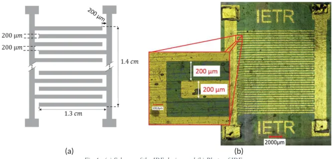
The IDE structure has been realized in several steps. First, a 2.7 μm thick photoresist was deposited at 3000 rpm for 28 seconds by spin coating on the surface of the PZT (Fig 3 (b)). Then, the desired patterns of IDE were drawn by photolithography. The resin that has not been insolated is removed by a development process (Fig 3 (c)). A gold layer 100 nm thick is deposited on the entire surface of the sample by Joule evaporation (Fig 3 (d)). To reveal the electrodes, the residual resin and gold are removed by an acetone bath (Fig 3 (e)). The interdigitated electrodes were made of 18 pairs of gold fingers with a thickness of 100 nm. The fingers of the IDE have a length of 1.3 cm, a width of 200 µm for a gap between two fingers of 200 µm (Fig 4).
(a) (b)
Fig 4 : (a) Scheme of the IDE design and (b) Photo of IDE.
To achieve this structure, the PZT film and the IDE must be transferred to an insulating and flexible film polymer. To carry out the transfer of PZT to Polyethylene Terephthalate (PET) substrate, a SU-8 2005 epoxy photoresist adhesion layer (Fig 3 (f)) is added by a spin-coating technique to ensure a good bonding between the PZT and the polymer substrate. It is possible to choose the thickness of this epoxy layer by modifying the rotational speed of the spin-coater. A speed of 4000 rpm yields a layer of approximately 7.5 μm. Thanks to the technique used, a good bonding is obtained between the PZT and the resin as well as the encapsulation of the interdigitated electrodes (IDE). The adhesion between the resin and the polymer substrate (PET) is easily achieved thanks to the good compatibility of these two layers. Interestingly, the epoxy layer also isolates the electrode from ambient air, thus providing protection against electric arcs during the polarization step.
Once this layer has been deposited, the PZT with the IDE is transferred to the PET sheet with a thickness of 75 μm by thermal welding (Fig 3 (g)). The aluminum substrate is etched with ferric chloride [FeCl3] (Fig 3 (h)). A second sheet of PET 320 μm thick is thermally welded to encapsulate the PZT and
thus protect it (Fig 3 (i)). The dimensions and shape of the PET sheets can be modified according to the source of vibration (Fig 5 (b)). In this article, the PET is cut into a beam shape 11 cm long and 2.2 cm wide to have a resonance frequency of less than 20 Hz. These large dimensions could be achieved only thanks to the modified fabrication process in comparison with previous work [20]. In the latter case (Fig 5 (a)), the final size of the piezoelectric generator was limited (2.5 cm x 2.5 cm) because the IDE realization step is carried out after PZT transfer onto the polymer substrate. As a matter of fact, the surface area of the sample must be small enough to achieve homogenous deposition the photosensitive resin by spin coating under high speed rotation. In the present study, the IDE electrode pattern (steps d and e in Fig.3) is achieved before the realization of the PET/epoxy/PZT trilayer (steps f, g and f in Fig.3). Thus, the advantage of this process compared to [19] and [20] are the larger dimensions and the shape tunability that can be given to the generator.
Fig 5 : IDE micro-generator developed (a) by Dufay and al [20]. (b) in the present work.
Finally, thin copper wires were fixed onto metal terminals by conductive paste and a poling process was performed at 100 °C onto a hot-plate under an applied DC electric field of 100 kV/cm for approximately 2 hours.
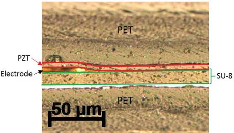
Cross-section image of the micro-generator were realized (Fig 6) to show the good bonding between PZT and PET and the encapsulation of the IDE.
Fig 6 : Optical microscopy photograph of complete cross-section of micro-generator. The red line indicates the PET/PZT interface.
The photos presented in Fig 7 show the PZT surface after transfer onto the PET substrate with and without the use of an adhesive layer of SU-8 epoxy. In Fig 7-a, no adhesive layer was used, we can see that the PZT exhibits several cracks. Conversely, in Fig 7-b, the PZT layer is intact. Indeed, the layer of SU-8 epoxy allowed to maintain the PZT layer and the electrode during the transfer, thus limiting the appearance of cracking. On these two images, the observed vertical bands are due to the rolling of the aluminum substrate and transferred onto the PZT.
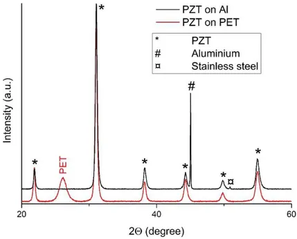
The X-ray diffraction (XRD) patterns of PZT/Al and PZT/PET have been performed with a Siemens D8 diffractometer using Cu- Kα radiation (λ = 1.5406 Å ) and scanning from 2Θ = 20° to 2Θ = 60° at 0.03 °/s
scan rate, and are given in Fig 8. The two diagrams are nearly identical except for the substrate peaks. Indeed, the main peak of aluminum is replaced by the peak of PET, but the position of all PZT remain unchanged. Since the base surface is not perfectly flat in both cases, a slight shift in 2Θ angle is observed. These XRD diagrams confirm that the quality of the PZT layer is maintained after the transfer.
(a) (b)
Fig 7 : Images of PZT layer after transfer onto polymer substrate (a) without SU-8 layer and (b) with SU-8 layer.
4. EXPERIMENTS
4.1. Experimental setup
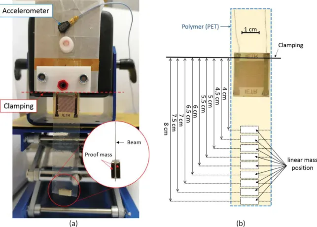
The experimental setup used to measure the harvested electric power generated by mechanical vibrations is shown in Fig 9. The beam is clamped (Fig 10 (a)) at one end in contact with the shaker (TMS K2007E01) controlled by a function generator, and free at the other end. The acceleration measurement is performed with a PCB Piezotronics 352C22 accelerometer with a sensitivity of 10 mV/g. The voltage across the micro-generator as well as the accelerometer is recorded using a Tektronix TBS 1052B-EDU oscilloscope. The length, width and height of the cantilever beam are 8.2 cm, 2.2 cm, 400 μm respectively.
For this experiment, two magnetic proof masses (1 cm x 0.4 cm x 0.1 cm) of 0.3 g were arranged on each side of the beam at different distances from the clamp (8 cm, 7.5 cm, 7 cm, 6.5 cm, 6 cm, 5.5 cm, 5 cm, 4.5 cm and 4 cm) (Fig 10 (b)), thus allowing to vary the resonance frequency of the device.
(a) (b)
Fig 10 : Photography of (a) experimental setup and (b) the PET/IDE/PZT/PET beam: diagram of the different mass positions.
Frequency and voltage responses were recorded for the linear mass distribution with an acceleration of 1 g (9.81 m/s2) and load resistances of 1, 5, 10, 50, 100 with voltage probe and 200 and 500 MΩ with
voltage divider bridge.
4.2. Experimental results
Fig 11 shows the frequency dependence of the output voltage of the piezoelectric generator across a fixed resistive load (RLOAD =100 MΩ) induced by sinusoidal mechanical excitation at frequencies ranging
from 8 Hz to 21 Hz for linear mass distribution. As expected, the different mass positions modify the resonance frequency. For a mass at 8 cm from the clamping, the maximum peak voltage is located at 9.9 Hz, which is the resonance frequency of the system for this configuration. One can also observe that the resonance frequency increases (10.5 Hz, 11.3 Hz, 12 Hz, 12.8 Hz, 13.6 Hz, 14.6 Hz, 15.3 Hz and 16 Hz) when the distance of the mass distribution relative to the attachment point decreases (7.5 cm, 7 cm, 6.5 cm, 6 cm, 5.5 cm, 5 cm, 4.5 cm and 4 cm). In this way, the micro-generator can operate in a frequency range from 9.9 Hz to 18 Hz.
Another characterization has been realized by measuring the output voltage UR for five different load
resistances at a fixed frequency (9.9 Hz), corresponding to the resonance for the proof mass positioned at 8 cm (Fig.12). This experiment was repeated for all the positions of the mass and the respective resonance frequency of the beams for an acceleration of 1 g (Fig.13).
Fig 11 : Typical piezoelectric generator response for at frequencies ranging from 8 Hz to 21 Hz and linear mass distribution.
Fig 12 : Voltage, current and power delivered by the micro-generator with a linear mass positioned at 8 cm and corresponding theoretical curves.
From these measurements, it can be deduced the values of the • voltage, and the harvested power P through the load resistance R by the use of the equations (10) and (11), theoretical curves have been obtained by the use of equations (9) to (11).
! = !0 1 + 2"2#2 (9) • = × ! (10) $= • × ! 2 (11)
The theoretical curves and experimental data of output voltage, current and power for a mass at 8 cm are plotted (Fig 12) with the five experimental measurements made with load resistances of 1, 5, 10, 50, 100, 200 and 500 MΩ. A good agreement between the experiment and the theory is observed. Thus, the load resistance value yielding maximum power is consistent with the calculated value %&'=
1 2()" obtained by deriving the expression of power [Eq.(1)] with respect to . The theoretical optimal resistance value is %&'= 280 MΩ at 9.9 Hz since the sample exhibits a very weak
1
2()"≈ capacitance around 60 pF."
The current and the voltage delivered by the micro-generator for different mass positions are shown in Fig 13 and the power curves in Fig.14.
(a) (b)
(a) (b)
Fig 14 : (a) Power delivered by the micro-generator with a linear mass distribution, (b) zoomed-in area near the power peak.
The open-circuit voltage delivered by the generator varies according to the position of the mass. It reaches about 360 V for a mass at 8 cm, to go down to 220 V with a mass at 4 cm. This causes a decrease in the maximum power of the micro-generator Fig 14. These figures highlight the influence of the mass on the beam for the energy harvesting and in particular on the excitation frequency as well as the voltage.
Fig 15 shows the evolution of the resonance frequency of the beam and the maximum harvested power according to the position of the mass. Thus, the resonance frequency increases and the maximum power decreases as the mass approaches the clamp. This shows that the maximum power extracted varies in ≅
for a constant acceleration of 1 g with a damping factor of 0.014, as expected theoretically with 1 )
equation (8)[22].
Fig 15 : Evolution of the maximum power delivered by the micro-generator according to the resonance frequency. In order to demonstrate the ability of a single micro-generator to harvest power from small vibration sources, the piezoelectric cantilever was subjected to a point excitation by human finger. Fig 16 shows the real time voltage response obtained following three consecutive punctual cantilever deflections.
Fig 16 : Voltage delivered by the micro-generator for punctual deformation at 100 MΩ.
For each punctual excitation, two phases are present, the bending phase which induces a low voltage of about 10V and a release phase which gives a peak voltage rise of about 300 V.
Finally, this unique micro-generator has also been tested for powering low-energy consumption micro electronic systems such as 110 commercial LED (C503D-WAN-CCBEB151) arrays. Besides, the number of LEDs used in the study has been chosen as a function of their forward voltage VF of 2.7 V which defines the voltage threshold required for the current to flow through the diode junction. With 110 LEDs the forward voltage is around 300V which is the limit that can be supplied with a micro-generator. These latter were connected in series and could be directly powered up without rectifier and charge circuits. The micro-generator was connected to the 110 very bright white LEDs and was then slightly bent by a finger, as shown in (Fig 17 (a)). By release, the LED arrays were simultaneously turned on, as shown in the captured image in Fig 17 (b) and in the inset. Moreover, it may be noticed that lightning LED array up with energy harvesting devices is a commonly performed experimental validation of piezoelectric micro-generators bent by human finger [19,25].
(a) (b)
Fig 17 : (a) Photograph of the 110 commercial white LEDs arrayed in series (b) A snapshot showing the instantaneous lighting up when the micro-generator was released after slight bending by human finger.
In the literature there is a wide range of piezoelectric generators for different low frequency energy harvesting applications (<20 Hz). Table 1 summarizes the main characteristics of flexible piezoelectric micro-generators found in the literature (including polymer/polymer and hybrid oxide/polymer bilayered structure) and allowing a comparison with the micro-generator developed in the present study. It should be emphasized that the output power density depends on the shape of the harvester, the type of the mechanical excitation (force, acceleration), the input frequency and amplitude. Nevertheless, the collected data between 0.3 and 10 Hz still demonstrate the energy conversion with IDE configuration is more efficient than with MIM configuration and the harvested power density with the generator presented in this work is slightly higher than those reported in the literature.
Table 1 : Characteristics of flexible piezoelectric generators.
Piezoelectric material [substrate] Electrode Active area Excitation
frequency Power density Han and al.
[26] Polyvinylidene fluoride (PVDF) [ PET] MIM 8 cm2 10 Hz 3,84 µW/ cm2 Chen [27] PVDF [Polyimide Kapton®] MIM 0.8 cm2 1 Hz 375 nW/cm2 Ma and al. [28] PVDF [Mylar] MIM 3.6 cm 2 5.13 Hz 4.33 µW/cm2 Do and al. [29] PZT[PET] MIM 1 cm2 1.2 Hz 4.2 nW/cm2
Yeo and al.
[30] PZT[PET] MIM 4 cm2 6 Hz 12.75 µW/cm2
Park and al.
[19] PZT[PET] IDE 2,25 cm2 0.3 Hz 39,1 µW/cm
2
Hwang and
al. [25] PZT[PET] IDE 7,2 cm
2 0.8 Hz
13,8 µW/cm2 Jeon and al.
[31] PZT[MgO] IDE 1,71 cm2 0.4 Hz 47.5 µW/cm
2
This work PZT[PET] IDE 1,82 cm2 9.9 Hz
63.5 µW/cm2
5. CONCLUSIONS
In this paper, we have developed and characterized a flexible piezoelectric cantilever-basedmicro-generator for energy harvesting purposes. The system is composed of an active PZT thin film deposited onto a polymer substrate. The novelty of the study mainly resides in the fabrication technique which has been adapted to enable i) the PZT transfer to a polymer only at the last step of process and ii) the IDE electrodes on the free aluminium PZT side. Therefore, the dimensions of the cantilever (i.e. the dimensions of the polymer sheet) may be easily modified, yielding a beneficial tuning of its mechanical resonance frequency in order to optimize the energy conversion efficiency. The maximum output power was 127 μW, when the micro-generator was excited with a sinusoidal acceleration of 1 g at 9.9 Hz and a mass at 8 cm of clamping. The position of the mass on the beam makes it possible to vary the resonance frequency of the micro-generator allowing the generator to operate over a frequency range of 9.9 to 16 Hz. In this way, we can easily adjust it for harvesting applications, such as human motion having a frequency dominant bass (< 20 Hz). However, since the output power is inversely proportional to the natural frequency of the generator for a given acceleration, it is generally preferable to operate at the lowest available fundamental frequency. At last, in the field of low frequency and flexible piezoelectric energy harvesters, the study demonstrated that the output power density places the developed piezoelectric micro-generators at the state-of-the-art level. Thus, their efficient mechanoelectrical energy conversion, combined with their robustness and flexibility make these devices very attractive for wind flow energy harvesting. A specific target application could be the self-powering of low-consumption communicating sensors for railway monitoring implemented for instance in unlit areas like tunnels, where power cannot be supplied by solar cells.
ACKNOWLEDGEMENTS
The authors gratefully acknowledge financial support from the French Region Pays de la Loire via the RFI program WISE.
REFERENCES
[1] F. Qian, T.-B. Xu, L. Zuo, Piezoelectric energy harvesting from human walking using a two-stage amplification mechanism, Energy. 189 (2019) 116140. https://doi.org/10.1016/j.energy.2019.116140. [2] J.J.H. Paulides, J.W. Jansen, L. Encica, E.A. Lomonova, M. Smit, Human-powered small-scale generation
system for a sustainable dance club, in: 2009 IEEE International Electric Machines and Drives Conference, 2009: pp. 439–444. https://doi.org/10.1109/IEMDC.2009.5075243.
[3] W. Hwang, K.-B. Kim, J.Y. Cho, C.H. Yang, J.H. Kim, G.J. Song, Y. Song, D.H. Jeon, J.H. Ahn, S. Do Hong, J. Kim, T.H. Lee, J.Y. Choi, H. Cheong, T.H. Sung, Watts-level road-compatible piezoelectric energy harvester for a self-powered temperature monitoring system on an actual roadway, Applied Energy. 243 (2019) 313–320. https://doi.org/10.1016/j.apenergy.2019.03.122.
[4] K. Zhang, X. Wang, Y. Yang, Z.L. Wang, Hybridized Electromagnetic–Triboelectric Nanogenerator for Scavenging Biomechanical Energy for Sustainably Powering Wearable Electronics, ACS Nano. 9 (2015) 3521–3529. https://doi.org/10.1021/nn507455f.
[5] K. Fan, Y. Zhang, H. Liu, M. Cai, Q. Tan, A nonlinear two-degree-of-freedom electromagnetic energy harvester for ultra-low frequency vibrations and human body motions, Renewable Energy. 138 (2019) 292– 302. https://doi.org/10.1016/j.renene.2019.01.105.
[6] R. Ahmed, Y. Kim, M.U. Mehmood, Zeeshan, U. Shaislamov, W. Chun, Power generation by a thermomagnetic engine by hybrid operation of an electromagnetic generator and a triboelectric nanogenerator, International Journal of Energy Research. 43 (2019) 5852–5863. https://doi.org/10.1002/er.4691.
[7] D. Miki, M. Honzumi, Y. Suzuki, N. Kasagi, Large-amplitude MEMS electret generator with nonlinear spring, in: 2010 IEEE 23rd International Conference on Micro Electro Mechanical Systems (MEMS), IEEE, Wanchai, Hong Kong, China, 2010: pp. 176–179. https://doi.org/10.1109/MEMSYS.2010.5442536.
[8] Y. Zhang, T. Wang, A. Luo, Y. Hu, X. Li, F. Wang, Micro electrostatic energy harvester with both broad bandwidth and high normalized power density, Applied Energy. 212 (2018) 362–371. https://doi.org/10.1016/j.apenergy.2017.12.053.
[9] G. Tang, F. Cheng, X. Hu, B. Huang, B. Xu, Z. Li, X. Yan, D. Yuan, W. Wu, Q. Shi, A Two-Degree-of-Freedom Cantilever-Based Vibration Triboelectric Nanogenerator for Low-Frequency and Broadband Operation, Electronics. 8 (2019) 1526. https://doi.org/10.3390/electronics8121526.
[10] W. Liu, Z. Wang, G. Wang, G. Liu, J. Chen, X. Pu, Y. Xi, X. Wang, H. Guo, C. Hu, Z.L. Wang, Integrated charge excitation triboelectric nanogenerator, Nat Commun. 10 (2019) 1–9. https://doi.org/10.1038/s41467-019-09464-8.
[11] J. Palosaari, M. Leinonen, J. Juuti, H. Jantunen, The effects of substrate layer thickness on piezoelectric vibration energy harvesting with a bimorph type cantilever, Mechanical Systems and Signal Processing. 106 (2018) 114–118. https://doi.org/10.1016/j.ymssp.2017.12.029.
[12] D. Upadrashta, Y. Yang, Nonlinear piezomagnetoelastic harvester array for broadband energy harvesting, Journal of Applied Physics. 120 (2016) 054504. https://doi.org/10.1063/1.4960442.
[13] K. Fan, Q. Tan, Y. Zhang, S. Liu, M. Cai, Y. Zhu, A monostable piezoelectric energy harvester for broadband low-level excitations, Appl. Phys. Lett. 112 (2018) 123901. https://doi.org/10.1063/1.5022599.
[14] S.S. Won, H. Seo, M. Kawahara, S. Glinsek, J. Lee, Y. Kim, C.K. Jeong, A.I. Kingon, S.-H. Kim, Flexible vibrational energy harvesting devices using strain-engineered perovskite piezoelectric thin films, Nano Energy. 55 (2019) 182–192. https://doi.org/10.1016/j.nanoen.2018.10.068.
[15] K. Tao, H. Yi, L. Tang, J. Wu, P. Wang, N. Wang, L. Hu, Y. Fu, J. Miao, H. Chang, Piezoelectric ZnO thin films for 2DOF MEMS vibrational energy harvesting, Surface and Coatings Technology. 359 (2019) 289– 295. https://doi.org/10.1016/j.surfcoat.2018.11.102.
[16] J. Yang, C. Si, G. Han, M. Zhang, J. Ning, F. Yang, X. Wang, Resonant Properties of a T-sbape Aluminum Nitride Piezoelectric Structure for MEMS Device, in: 2019 International Conference on Manipulation, Automation and Robotics at Small Scales (MARSS), 2019: pp. 1–5. https://doi.org/10.1109/MARSS.2019.8860965.
[17] R. Seveno, D. Averty, Ultra light tunable capacitor based on PZT thin film deposited onto aluminium foil, Journal of Sol-Gel Science and Technology. 68 (2013) 175–179. https://doi.org/10.1007/s10971-013-3149-8.
[18] T. Dufay, R. Seveno, B. Guiffard, J.- Thomas, New process for transferring PZT thin film onto polymer substrate, in: 2016 Joint IEEE International Symposium on the Applications of Ferroelectrics, European Conference on Application of Polar Dielectrics, and Piezoelectric Force Microscopy Workshop (ISAF/ECAPD/PFM), 2016: pp. 1–4. https://doi.org/10.1109/ISAF.2016.7578085.
[19] K.-I. Park, J.H. Son, G.-T. Hwang, C.K. Jeong, J. Ryu, M. Koo, I. Choi, S.H. Lee, M. Byun, Z.L. Wang, K.J. Lee, Highly-Efficient, Flexible Piezoelectric PZT Thin Film Nanogenerator on Plastic Substrates, Advanced Materials. 26 (2014) 2514–2520. https://doi.org/10.1002/adma.201305659.
[20] T. Dufay, B. Guiffard, R. Seveno, J.-C. Thomas, Energy Harvesting using a Lead Zirconate Titanate (PZT) Thin Film on a Polymer Substrate, Energy Technology. 6 (2018) 917–921. https://doi.org/10.1002/ente.201700732.
[21] C.B. Williams, R.B. Yates, Analysis of a micro-electric generator for microsystems, Sensors and Actuators A: Physical. 52 (1996) 8–11. https://doi.org/10.1016/0924-4247(96)80118-X.
[22] S.P. Beeby, M.J. Tudor, N.M. White, Energy harvesting vibration sources for microsystems applications, Meas. Sci. Technol. 17 (2006) R175–R195. https://doi.org/10.1088/0957-0233/17/12/R01.
[23] T. Dufay, B. Guiffard, J.-C. Thomas, R. Seveno, Transverse piezoelectric coefficient measurement of flexible lead zirconate titanate thin films, Journal of Applied Physics. 117 (2015) 204101. https://doi.org/10.1063/1.4921588.
[24] R. Seveno, J. Carbajo, T. Dufay, B. Guiffard, J.C. Thomas, Flexible PET/Al/PZT/Al/PET multi-layered composite for low frequency energy harvesting, J. Phys. D: Appl. Phys. 50 (2017) 165502. https://doi.org/10.1088/1361-6463/aa6373.
[25] G.-T. Hwang, V. Annapureddy, J.H. Han, D.J. Joe, C. Baek, D.Y. Park, D.H. Kim, J.H. Park, C.K. Jeong, K.-I. Park, J.-J. Choi, D.K. Kim, J. Ryu, K.J. Lee, Self-Powered Wireless Sensor Node Enabled by an Aerosol-Deposited PZT Flexible Energy Harvester, Advanced Energy Materials. 6 (2016) 1600237. https://doi.org/10.1002/aenm.201600237.
[26] M. Han, W. Liu, X. Zhang, B. Meng, H. Zhang, Investigation and characterization of an arc-shaped piezoelectric generator, Science China Technological Sciences. 56 (2013) 2636–2641. https://doi.org/10.1007/s11431-013-5373-4.
[27] D. Chen, T. Sharma, J.X.J. Zhang, Mesoporous surface control of PVDF thin films for enhanced piezoelectric energy generation, Sensors and Actuators A: Physical. 216 (2014) 196–201. https://doi.org/10.1016/j.sna.2014.05.027.
[28] X. Ma, A. Wilson, C.D. Rahn, S. Trolier-McKinstry, Efficient Energy Harvesting Using Piezoelectric Compliant Mechanisms: Theory and Experiment, J. Vib. Acoust. 138 (2016). https://doi.org/10.1115/1.4032178.
[29] Y.H. Do, W.S. Jung, M.G. Kang, C.Y. Kang, S.J. Yoon, Preparation on transparent flexible piezoelectric energy harvester based on PZT films by laser lift-off process, Sensors and Actuators A: Physical. 200 (2013) 51–55. https://doi.org/10.1016/j.sna.2012.10.034.
[30] H.G. Yeo, X. Ma, C. Rahn, S. Trolier‐McKinstry, Efficient Piezoelectric Energy Harvesters Utilizing (001) Textured Bimorph PZT Films on Flexible Metal Foils, Advanced Functional Materials. 26 (2016) 5940–5946. https://doi.org/10.1002/adfm.201601347.
[31] C.K. Jeong, S.B. Cho, J.H. Han, D.Y. Park, S. Yang, K.-I. Park, J. Ryu, H. Sohn, Y.-C. Chung, K.J. Lee, Flexible highly-effective energy harvester via crystallographic and computational control of nanointerfacial morphotropic piezoelectric thin film, Nano Research. 10 (2017) 437–455. https://doi.org/10.1007/s12274-016-1304-6.
![Fig 2 : Schematics diagram of the generator, developed by Williams and Yates [21].](https://thumb-eu.123doks.com/thumbv2/123doknet/11522312.294824/5.892.134.742.831.994/fig-schematics-diagram-generator-developed-williams-yates.webp)