Vincent Denoël Michael Hortmanns Gerhard Sedlacek
Practical design of cables and hangers subjected to rain-wind
induced vibrations
Abstract (to be translated in German):.
Rain-wind induced vibrations have been widely studied during the last decades. Today it is desirable to use the experience gathered in this field in order to develop a practical design procedure offering both security and economy. After a restricted review of some analytical models, this paper points out the need for a semi-empirical method if the complexity of this design procedure has to be kept at its minimum. Based on measured data collected during field tests and wind tunnel experiments, a new proposal is suggested.
Abstract (in English)
Rain-wind induced vibrations have been widely studied during the last decades. Today it is desirable to use the experience gathered in this field in order to develop a practical design procedure offering both security and economy. After a restricted review of some analytical models, this paper points out the need for a semi-empirical method if the complexity of this design procedure has to be kept at its minimum. Based on measured data collected during field tests and wind tunnel experiments, a new proposal is suggested.
1. Introduction
In the mid-eighties, Hikami and Shiraishi [4] observed the first outward signs of rain-wind induced vibrations of stay cables. Since then a growing interest has been devoted to this very particular fluid-structure interaction phenomenon, occurring under simultaneous conditions on wind direction, wind velocity and rain intensity. Because of the undesirable expensiveness of damages caused by this phenomenon, a lot of effort has been put on several aspects.
First, field observations started to take place in many countries of the world ([2], [5], [8], [9], [17]). Visual investigations as well as accurate monitoring revealed the significant occurrence of these vibrations.
Secondly, experimental simulations helped in surrounding the strict conditions under which rain-wind induced vibrations of cables and hangers can happen ([6], [10], [14]).
The rain-wind induced vibrations also gave rise to the development of complex analytical models. Many of them are non linear dynamical models and require advanced numerical simulation tools. ([1], [2], [11], [16]).
Although a quality research has been spread in all these theoretical and experimental fields, a fourth aspect of the problem consists in developing countermeasures in order to limit these vibrations ([3]).
After more than twenty years of unflagging efforts, the phenomenon is now well understood. Some analytical and semi-empirical models have been developed in order to account for these vibrations at a design stage. After a brief review and comparison of some of these design procedures, a new proposal, clearly derived for practical engineers, is submitted.
2. Phenomenology
As a brief summary of the last twenty years of research, these findings can be stated:
• the rain-wind induced vibrations of cables is a consequence of the oscillations of one or two rivulets attached to the cable;
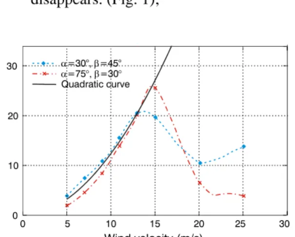
• the phenomenon is limited to a narrow velocity range (5m/s to 15m/s). Indeed on the one hand small wind velocities induce too small oscillations of the rivulet and thus insignificant vibrations of the cable; on the other hand, above a critical velocity, the rivulet is disturbed and the phenomenon disappears. (Fig. 1); 0 5 10 15 20 25 30 0 10 20 30 α=30°, =45°β α=75°, β=30° Quadratic curve Wind velocity (m/s)
Figure 1: Amplitudes of vibration (in cm) as a function of the wind velocity, for several cable inclinations (α) and wind direction (β)
• Complex analytical models [11] and experimental setups [17] have shown the
existence of several kinds of excitation: one stable lower rivulet only for smaller wind velocities, two stable rivulets (upper and lower) for higher wind velocities. This latter case can again be divided into two parts distinguishing the in-phase and the out-of-phase oscillations of the rivulets.
3. Theoretical models
Up to now a lot of experiment has been performed and it would be desirable to predict analytically the rain-wind induced vibration phenomenon. This daring objective should be considered in different contexts, amongst which the design stage.
In this section some existing methods are presented. Their advantages and drawbacks are discussed. Naturally, each theoretical model aims at reproducing the best some experimental measurements as well as the phenomenological items presented the previous section. Some models are complex, require a lot of parameters but are precise; others are simpler but less accurate. In the selection of a usable design procedure, this balance between complexity and accuracy must clearly be studied.
Amongst the whole set of design procedures, two important subgroups can be distinguished: the purely analytical models and the semi-analytical models. Some of them are described in the next section.
3.1. Common hypothesis
The theoretical models have some hypothesis in common: • they all postulate a quasi-steady flow, i.e. that the
movements of the structure are so slow that they do not affect significantly the fluid flow around it. The aerodynamic loading is thus expressed as a function of the classical aerodynamic coefficients (drag and lift on the cable, turning moment on the rivulet). • experimental investigations ([11], [14]) have shown
that the aerodynamic coefficients measured with two rivulets placed between 150° and 180° from each other can be derived from the aerodynamic coefficients measured with one rivulet only. This feature is now admitted and adopted as such by all. • because of their evident complexity, the purely
analytical models generally postulate a uniform rivulet along the cable. Furthermore, the most usual ones are 4-DOF analytical models representing the position of the cable ( y , z ) and the positions of both rivulets (ϕ1 and ϕ2). The governing equations can be written: ( ) ϕ ϕ ⋅⋅ ⋅⋅ ⋅⋅ ⋅⋅ = 1 2 ... T y z F (1)
where F is a set of four non linear functions of state space variables (y z, , , , , , ,ϕ ϕ1 2 y z⋅ ⋅ ⋅ϕ ϕ1 ⋅2) and parameters (wind velocity, mass and shapes of rivulets, cable characteristics, etc.)
3.2. Major differences
In spite of the apparent similarities presented in the previous paragraph, some major differences should be underlined:
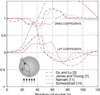
• different aerodynamic coefficients are used. Their measurement has been performed many times with various tube sections and (artificial) rivulet shapes. Figure 2 represents a comparison of some measured drag and lift coefficients. It indicates a similar global outline but however important discrepancies mainly due to the test conditions.
• the purely analytical models differ from each other in the way the rivulet is linked to the cable. 0 20 40 60 80 100 120 -1 -0.5 0 0.5 1 Nahrath [11] φ Schwarzkopf [14] Gu and Lu [3] James and Truong [7]
LIFT COEFFICIENTS DRAG COEFFICIENTS
Position of rivulet ( )φ
Figure 2. Comparison of measured aerodynamic coefficients
3.3 Purely analytical models
The particularities of the rain-wind induced vibrations listed in section 2 reveals the complexity of the phenomenon and lets easily guess that a linear dynamic model is not suitable for this kind of behaviour.
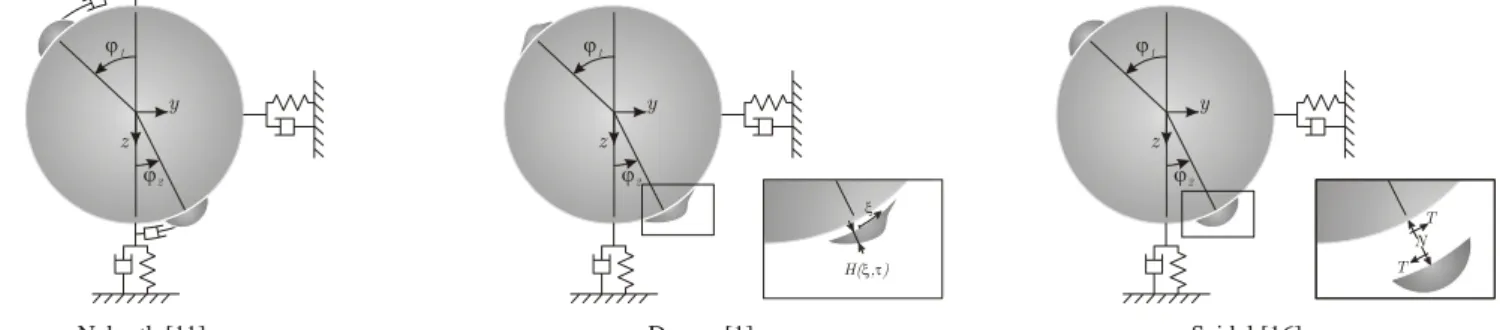
z y ϕ2 ϕ1 N T T z y ϕ2 ϕ1 Nahrath [11] Seidel [16] z y ϕ2 ϕ1 H( , )ξ τ ξ Dreyer [1]
Figure 3: Comparative illustration of some analytical models. These models are mainly different from each other in the way the rivulet is linked to the cable
As a first noticeable theory, Nahrath ([11]) presents an interesting 4-DOF analytical. Under the common assumptions listed in section 2, this model postulates a given rivulet shape and rivulet mass. It supposes also that the rivulet is linked to the cable through viscous effects (see. Fig. 3). More precisely the link is simply modelled by a viscous damper. The usual tools of non linear dynamic allow reproducing, for this model, stable and unstable equilibrium points, bifurcations wind velocities and amplitudes of limit cycles.
Dreyer ([1]) upgraded this non linear dynamic model: the position of the rivulet, its shape and its connexion to the structure is assessed by means of the Navier-Stokes equations (Fig. 3). Moreover in these applications a turbulent wind flow is considered. This makes the usual analytical tools unsuitable and implies the use of time domain simulations.
In Seidel’s 4-DOF model ([16]), the link between the rivulet and the cable is modelled by means of shear (T) and normal (N) reactive forces. In this model, a linear structural model is used for the cable. Lift and drag coefficients are turned to their simplest forms (Heaviside functions). Furthermore it should be noted that no turning moment coefficient is considered for the rivulets; their equilibrium is simply written in terms of the shear and normal reactive forces.
3.4 Semi-analytical models
Schwarzkopf’s aim is to develop a simple theoretical model. Since the complete modelling of the phenomenon needs to include complex non linear dynamic features, this goal is achieved thanks to a semi-analytical model. The complexity of the phenomenon is thus embedded in experimental investigations and a semi-empirical formulation. Exactly as for the purely analytical models a quasi-steady approach is considered; the aerodynamic force exciting the cable is:
ρ = 2 , , 2 err d err d F C v d (2)
where d , ρ, Cerr d, are respectively the cable diameter,
the air density and the aerodynamic coefficient. This relation holds for low wind velocities ( v ) only. Above a
critical wind velocity (see Fig. 1) the rivulet is not stable anymore and the phenomenon disappears. Figure 1 shows that the exciting force corresponding to this critical velocity is a good design value.
Schwarzkopf’s design procedure hides the complex behaviour of the rain-wind induced vibrations in a semi-empirical formula (see Fig. 4) giving the critical velocity as a function of the cable diameter and the natural frequency. The effortless determination of this critical velocity gives thus a direct access to the exciting force. As a last step, under the assumption of a resonant monoharmonic motion (as previously proposed by Verwiebe and Sedlacek [17]), the displacement of the cable can be computed easily:
π δ ξ = = 2 gen gen gen gen F F Y K K (3)
where Kgen, δ and ξ represent respectively the generalized stiffness, the logarithmic decrement and the damping ratio.
3.5 Design rules
Present some existing design rules ? Germany? Canada? US ? Japan ? France ?
4. Comparison
From a theoretical point of view, rain-wind induced vibrations are clearly identified as particular stable orbits or limit cycles. Their existence can be justified by non linear dynamic models only, which explains the complexity of the purely analytical models. It is not really easy to state which non linear effect is strictly necessary in order to model the rain-wind induced vibrations. For example, Seidel’s model ([16]) does not require any non linear structural behaviour (i.e. cable-like behaviour) in order to produce rain-wind induced vibrations. Moreover he demonstrates that the phenomenon can be
generated even with very simple aerodynamic coefficients (as functions of the rivulet position).
Purely analytical models are all able to reproduce some experimental results; this has a tendency to make them reliable. But, because of the wide diversity of link conditions between the rivulets and the cable, it seems that the limit cycle can be generated with several significantly different models, which worsen the clear identification (and reproduction) of the phenomenon. From a practical point of view, the critical velocity is the design velocity, i.e. the velocity giving the most important cable amplitudes. Since the wind velocity is considered as an input parameter in purely analytical models, they clearly require a parametric analysis in order to determine critical velocities and design cable amplitudes. Furthermore each of these analyses is relatively complex and difficulty imaginable in a standard design office at the design stage.
For this reason a semi-analytical model hiding an important part of the complexity of the problem (the estimation of the critical velocity) is an interesting tool. Even if the design procedure proposed by Schwarzkopf and Sedlacek ([15]) seemed inept in some cases, a deeper investigation in this direction can turn their proposition into a convenient design procedure.
5. New proposal for the design
In [15] it is proposed to estimate the critical velocity from the knowledge of the cable diameter and frequency. Upon the physical intuition lying under the expected relationship between these three parameters, the authors also justify the convenience of this relation by the fair correlation obtained on experimental results.
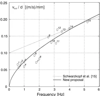
The proposition of Schwarzkopf and Sedlacek is represented in dashed lines on Fig. 4. It is the result of a fitting of wind-tunnel results obtained by Schwarzkopf (points 9, 12, 13, 14 and 15). Peil ([12]) has enlightened
the excess of security provided by this relation, mainly in the low natural frequency domain. Based on wind tunnel measurements and on-site measurements collected from all over the world and for a wide range of cable diameters and frequencies, a new proposal is introduced. Figure 4 shows that the semi-empirical relation:
[
]
[ ] ⎛ ⎞ = ⎜ ⎟ ⎝ ⎠ 0.6 / / 0.0735 / [ ] krit v m s f d mm Hz (4)provides a very good estimate for the critical velocity. This relation has been obtained by fitting the frequency, diameter and (mean, if necessary) critical velocity of the whole set of data given in Table 1. 0 1 2 3 4 5 6 0 0.05 0.10 0.15 0.25 New proposal Schwarzkopf et al. [15] 2 Frequency [Hz] 0.20 3 1 4 7 8 6 10 9 1213 14 15 v / d [(m/s)/mm]krit 5 11
Figure 4: Modification of Schwarzkopf’s formula for the expression of the critical velocity as a function of the cable diameter and natural frequency
# Frequency Velocity Diameter Author Measurement
1 0.57 Hz [8; 13] m/s 160 mm Saito et al., 1994 (Japan) Wind tunnel
2 0.625 Hz 11 m/s 194 mm Zou et al., 2003 (USA) On-site (Fred Hartmann Bridge) 3 0.8 Hz 14 m/s 200 mm Geurts, 1999 (NL) On-site (Erasmus Bridge) 4 1 Hz [8; 12] m/s 168 mm Flamand, 1994 (F) Wind tunnel
5 1 Hz [8.5; 9] m/s 120 mm Gu et al., 2005 (China) Wind tunnel 6 1.68 Hz [4.5; 5.5] m/s 54 mm Matsumoto, 2003 (Japan) Wind tunnel
7 1.8 Hz [7; 13] m/s 140 mm Hikami, 1986 (Japan) On-site (Meikonishi Bridge) 8 2 Hz [10; 13] m/s 140 mm Hikami, 1988 (Japan) Wind tunnel
9 2.6 Hz 16 m/s 110 mm Schwarzkopf, 2004 (D) Wind tunnel 10 2.8 Hz [12; 22] m/s 130 mm Lüesse et al., 1996 (D) On-site (Elbebrücke) 11 3.1 Hz [11; 15] m/s 100 mm XXXX, 2003 (D) On-site (Lunebrücke) 12 3.2 Hz 18.5 m/s 110 mm Schwarzkopf, 2004 (D) Wind tunnel 13 3.5 Hz 18 m/s 110 mm Schwarzkopf, 2004 (D) Wind tunnel 14 4 Hz 19 m/s 110 mm Schwarzkopf, 2004 (D) Wind tunnel 15 5.2 Hz 21 m/s 110 mm Schwarzkopf, 2004 (D) Wind tunnel
With this proposal, the critical velocity-frequency couples seem to locate interestingly around the proposed relation. On the one hand, this could be surprising. Indeed based on a purely analytical model, Seidel et al. demonstrates that the critical velocity depends for instance on the cable inclination .On the other hand it should be considered that practical design restrictions lead the designers to common solutions. It is thus not inconceivable that so many reported cases exhibit a common behaviour. The purpose of the new proposal is exactly to catch it in a new more convenient relation.
Because of its evident simplicity, the linear resonant response (Eq. 3) remains certainly the best assumption at the design stage for the estimation of the cable amplitude. Even if the non linearity of the loading process could be circumvented, it could be claimed that a more complex non linear dynamic model has to be considered, again, but for the computation of the structural response. Since the purpose of the simple design method exposed in this paper is to avoid this complex non linear modelling, the non linear characteristics of the system should be masked as it was, at the stage of the loading estimation, with the use of a semi-empirical method. In this attitude, the purely analytical models presented in section 3.3 could be used and eventually compared in order to determine behaviour factors (as it is the case in earthquake engineering). These factors allow the estimation of a non linear response from the application of a linear analysis only. They should thus be expressed as simple functions of available quantities.
It should be kept in mind that some quantities (as the damping ratio for example) are still vague at the design stage. Since the choice of an analysis procedure should be kinked to this accuracy a simple linear resonant approach is suitable in most cases.
6. Conclusions
The rigorous design of cables and hangers against wind-induced vibrations is a complex task. In order to help the designers, this paper underlines the complexity of purely analytical models and points out the ease of applicability of a semi-analytical approach.
In such a simplified approach the design procedure can be seen as two independent steps:
• the estimation of the loading;
• the computation of the amplitudes of vibration. At the first stage a new semi-empirical relation has been proposed in order to determine the critical wind velocity. Because it results in the largest amplitudes of vibration, this velocity can be seen as a design value. Compared to previous developments, the amended relation (Eq. 4) is also suitable for cables with low natural frequencies. Its effortless determination is the major key of the method and makes it convenient for a direct design.
Under the assumption of a linear resonant response, the second operation is straightforward. Indeed the resonant structural response can be expressed easily as a function of the loading, the stiffness and the damping. The usual uncertainties (mainly about this latter parameter) are such that the linear approach can be judged as sufficient.
7. Acknowledgements
The authors would like to acknowledge the Belgian National Fund for Scientific Research for having given a financial support to this research.
8. References
[1] Dreyer, O., Regen-Wind induzierte Seilschwingungen in laminarer und turbulenter Strömung, Promotion Arbeit, TU Braunschweig (2004).
[2] Geurts, C., van Staalduinen, Vrouwenvelder T., Reusink, J., Numerical modelling of rain-wind induced vibration: Erasmus Bridge, Rotterdam. Structural Engineering International, 8, (1998), S. 129-135.
[3] Gu, M., Lu, Q., Experimental investigation of rain-wind- induced vibration of cables in cable-stayed bridges and its mitigation, Journal of wind engineering and industrial aerodynamics, 93, S. 79-95 (2005).
[4] Hikami, Y., Shiraishi, N., Rain-wind induced vibrations of cables in cable stayed bridges. Journal of Wind Engineering and Industrial Aerodynamics, 29 (1988), S. 409-418.
[5] Hortmanns, M., Schwarzkopf ,D., Rheinquerung A44, Illverich – Berücksichtigung der Windwirkung im Bau- und Endzustand, Stahlbau 71 (2002), Heft 6.
[6] Hortmanns, M., Kraus, O., Sedlacek, G., Simulation of Rain-Wind-Induced vibrations in wind tunnel tests using a dry model with fluctuating position of the rivulet, 4th International Colloquium on Bluff Body Aerodynamics and Applications, Bochum, 2000
[7] James, F., Truong Q., Wind load on cylinder with spanwise protrusion, Engineering Mechanics Div., ç! S. 1573-1589 (1972).
[8] Lüesse, G., Ruscheweyh, H., Verwiebe, C., Günther, G. H., Regen-Wind induzierte Schwingungserscheinungen an der Elbebrücke Dömitz, Stahlbau, 65 (1998), S. 105-104.
[9] Matsumoto M., Yagi T., Goto M., Sakai S., Cable Aerodynamics Vibration at High Reduced Velocity, 4th international symposium on Cable Dynamics, Montréal (2001).
[10] Matsumoto M., Yagi T., Goto M., Sakai S., Rain-wind-induced vibration of inclined cables at
limited high reduced wind velocity region. Journal of Wind Engineering and Industrial Aerodynamics, 91 (2003), S.1-12.
[11] Nahrath, N., Modellierung Regen-Wind induzierter Schwingungen, Promotion Arbeit, TU Braunschweig (2003).
[12] Peil, Zuschriften, Stahlbau, 75 (2006) Heft 3.
[13] Robra, J., Regen-Wind induzierte Schwingungen von Schrägkabeln und Hängern - Ein Rechenmodell zur Vorhersage und Maßnahmen zur Verhinderung. Dissertation Technische Universität Wien (2003).
[14] Schwarzkopf, D., Regen-Wind-Induzierte Schwingungen, Grundlagen und ein Berechnungsmodell, Promotion Arbeit, RWTH Aachen (2004).
[15] Schwarzkopf, D., Sedlacek G., Regen-Wind induzierte Schwingungen - Ein Berechnungsmodell auf der Grundlage der neuesten Erkenntnisse. Stahlbau 74-12, (2005), S. 901-907.
[16] Seidel C., Dinkler D., Phänomenologie und Modellierung Regen-Wind induzierter Schwingungen, Bauingenieur, 79, (2004), S. 145-154.
[17] Verwiebe, C., Sedlacek G., Frequenz- und Dämpfungsmessungen an den Hängern von Stabbogenbrücken. Forschung Straßenbau und Straßenverkehrstechnik, 777 (1999).