HAL Id: hal-01960064
https://hal.insa-toulouse.fr/hal-01960064
Submitted on 19 Dec 2018
HAL is a multi-disciplinary open access archive for the deposit and dissemination of sci-entific research documents, whether they are pub-lished or not. The documents may come from teaching and research institutions in France or abroad, or from public or private research centers.
L’archive ouverte pluridisciplinaire HAL, est destinée au dépôt et à la diffusion de documents scientifiques de niveau recherche, publiés ou non, émanant des établissements d’enseignement et de recherche français ou étrangers, des laboratoires publics ou privés.
Study of an interference fit fastener assembly by finite
element modelling, analysis and experiment
Manuel Paredes, Naoufel Nefissi, Marc Sartor
To cite this version:
Manuel Paredes, Naoufel Nefissi, Marc Sartor. Study of an interference fit fastener assembly by finite element modelling, analysis and experiment. International Journal on Interactive Design and Manufacturing, Springer Verlag, 2012, 6 (3), pp.171-177. �10.1007/s12008-012-0146-z�. �hal-01960064�
Study of an interference fit fastener assembly
by finite element modelling, analysis and
experiment
International Journal for Interactive Design and Manufacturing, Springer, v 6, n 3, p 171-177, http://dx.doi.org/10.1007/s12008-012-0146-z
Manuel Paredes
Université de Toulouse; INSA, UPS, Mines Albi, ISAE; ICA (Institut Clément Ader); 135, avenue de Rangueil, F-31077 Toulouse, France
(0033) 5 61 55 99 56 / (0033) 5 61 55 97 00 [email protected]
Naoufel Nefissi
ESSTT (Ecole Supérieure de Sciences et Techniques de Tunis); Rue Ettahr El Haddad –Meuntfleurie, Tunis, Tunisia 2011
(00216) 71496066 / (00216) 71 391 166 [email protected]
Marc Sartor
Université de Toulouse; INSA, UPS, Mines Albi, ISAE; ICA (Institut Clément Ader); 135, avenue de Rangueil, F-31077 Toulouse, France
(0033) 5 61 55 99 56 / (0033) 5 61 55 97 00 [email protected]
Abstract
This paper exploits finite element simulations, analytical approaches and experimental data in a study of interference fit fasteners. The influence of both the friction factor and the interference level on the loss of axial load is investigated. An axisymmetric FE model using Abaqus shows that both parameters greatly influence the results. The study of the axial strain enables the most appropriate positions to be identified for sensors intended to investigate the validity of the finite element analysis results. An analytical study is performed to evaluate the relationship between interference level, friction factor and axial strain all along the screw axis. The axial loss of load and the radial pressure between the screw and the plates are also evaluated analytically.
1-Introduction
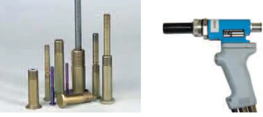
Bolt assemblies are a very common feature of engineering designs. When the bolt assembly is located in a critical sector, it may be replaced by an interference fit fastener. In that case, the screw contains a cylindrical part having a diameter larger than that of the hole where it is fitted and the two parts are locked together not only by the tightening load but also by the combined effect of friction and radial pressure due to interference in size at their interface diameter. Such screws can be pushed or pulled through the plates by means of specific tools.
Figure 1: examples of screws and dedicated tool
It has been proved that this process protects the fastener hole from crack propagation [1] and several studies have shown that using interference fit fasteners increases the fatigue life of structures [2]. For these reasons, interference fit fasteners are often used in space and aeronautical applications. We can assume that, in some cases, particularly when the interference level and the friction factor are too high, a large part of the tightening load can be lost through the tangential contact forces at the interference diameter. Moreover, a gap can be created between the screw head and the plate, creating an unauthorized defect. Of course, such a situation is not acceptable in an industrial application. In the preliminary design phase of such an assembly, it would be interesting to be able to evaluate the axial loss of load as a function of the two main design parameters: the interference level and the friction factor. It would also be of great interest to experimentally evaluate the axial load under the screw head and at the interface between plates.
Duprat et al. [3] have studied fatigue life prediction for an interference fit fastener. They show that, in 90% of cases, crack initiation does not take place at the edge of the hole but rather between the bore and the edge of the test specimen. Their
results were compared to a simplified two-dimensional finite element simulation but such a simulation does not enable the study of the load transfer between the screw and the two plates that are assembled. More recently, Li et al. [4] have studied the behaviour of an interference fit fastener with a single aluminium sheet. A photoelastic coating was bonded on to the external surfaces of the bolt in order to estimate the strain and the values were compared to a three-dimensional finite element simulation. In order to obtain accurate results, the entire introduction process was simulated precisely.
Studies performed on interference fit fasteners and bolt joints separately are also of interest.
Fontaine et al. [5-8] have studied the influence of a form defect on the shrinkage fit characteristics. They show that radial pressure always shows peaks at each contact edge. This tends to induce a non-constant loss of load along the screw axis. The edge effect has been precisely studied by testing the influence of various fit forms [9].
The average pressure at the shrink-fit interface is commonly calculated by using Lame’s equation [10, 11]. However, it has also been shown that an analytical study using Lame’s equation can differ significantly from a finite element simulation [12]. It will thus be interesting to analyse the difference between analytical and FE results.
Finite element studies of bolt assemblies are in common use and the coupling of bolt assemblies with other mechanical components has been studied [13, 14] by using three-dimensional FE simulations. Local studies can also be performed using 2D axisymmetric FE simulations [15] and give accurate results.
Experimental results are often obtained by placing strain gauges on the cylindrical part of the screw [15, 16]. In our case, the external diameter of the screw was involved in the contact with the plates so no strain gauge could be placed there. Another approach would be to use a fastener having an embedded fibre optic Bragg grating sensor as proposed by Hay [17]. This method has already given satisfactory results in assemblies [18] and could be tested in our study.
The aim of this paper is to define and evaluate methods to determine the axial load in interference fit fasteners which could be exploited in preliminary design. Based on a case study presented in section 2, a two-dimensional axisymmetric Finite Element approach is described in section 3. This finite element study is used as a reference. This kind of study can be performed during the preliminary design stage as a validation step. For easy management of the main parameters involved in the preliminary design stage (in our case the interference level and the friction factor), analytical approaches are often preferred and an analytical approach based on Lame’s equations is presented in section 4. A sensitivity study related to the case study is presented in section 5. It evaluates the performance of the analytical study relative to the finite element analysis. Both approaches are finally compared to experimental data in section 6.
2- Case study
2-1 Design of the screw
The screw, composed of a titanium alloy, enabled two aluminium alloy plates to be assembled. This design is similar to those used in the aeronautics industry.
Figure 2: Screw design.
The screw described in figure 2 can be divided into four parts.
From left to right, we can see the head, the shank, of diameter D, to be fitted in the holes, the thread, of diameter TD, that receives the nut to apply the tightening load and, finally, the part that enables the screw to be pulled through the plates.
In order to obtain a precise and very low friction factor, a coating was applied to the shank of the screw. Considering previous industrial work, the friction factor between the screw and the plates was estimated at f = 0.045. The friction factor between the plates was evaluated to be 0.4.
2-2 Geometrical data
In this study, D = 12.68 mm. Each plate was 24.75 mm thick and 132 mm long. The upper plate included a 1-mm chamfer. The reference value for the interference level was 0.80%. This means that ∆ = 0.102 mm (∆ is the difference between D and the inner diameter of the hole in the plates).
2-3 Operating process
The operating process was composed of several steps. The screw was first pulled through the plates by a dedicated tool that clenched the screw and applied a given introducing load. Then the load was relaxed, the tool was removed and the screw was broken near the beginning of the thread. Finally the nut was installed to provide the preload (tightening load) in the fastener. In our study, the tightening load F0 was equal to 50 kN. It induced a tensile stress in the screw that was about
50% of its UTS (Ultimate Tensile Strength).
3- Finite Element Study
3-1 Finite element model
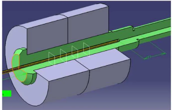
A finite element analysis was performed using Abaqus with an axisymmetric model. Three parts were considered: the screw and the two plates. The meshing was refined near the contact area in order to obtain more accurate results. The experimental process to measure the axial strain in the screw required a hole to be drilled in the screw axis. This hole (filled with epoxy resin) was included in the FE model because it could have a non-negligible influence on the global behaviour. The boundary conditions on the lower plate simulated the contact with the nut and with the tool used in the introducing step (see figure 3). As the screw was pulled through the plates, the introducing phase was simulated by managing the displacement and the load at the bottom of the screw. The tightening step was simulated by tangential loading on the thread part of the screw.
Figure 3 Detail of the Boundary Conditions
Contact was managed along the whole shank, under the screw head and between plates. Both contacts were simulated using the Abaqus default method for the normal behaviour and the penalty friction formulation for the tangential
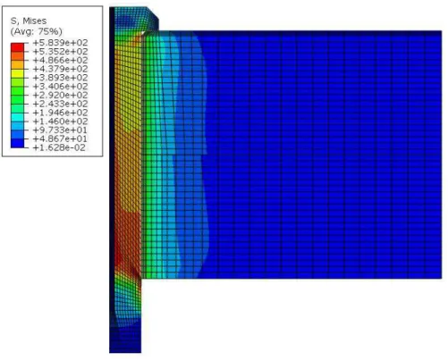
behaviour. In the case studied, the simulation showed that no plastic deformation appeared (even in the introduction phase). For that reason, an elastic simulation was considered. Figure 4 shows the Von Mises stress for the model when the tightening load was applied.
Figure 4 Von Mises stress
It can be seen that the plates are large enough for the stress in them to become negligible for large radius values. Moreover, the boundary conditions seem to simulate the effect of the nut correctly.
3-2 Radial pressure
The radial pressure computed on the shank of the screw is shown in figure 5.
Figure 5. Radial pressure on the shank
The results confirm that pressure is not uniform along the screw axis. They bring out not only the usual boundary effects at the beginning and end of engagement but also a discontinuity of pressure at the interface between the plates, which is highlighted for the first time.
3-3 Loss of axial tension
It was possible to evaluate the loss of axial load under the screw head, ∆FV, and at
the interface between plates, ∆FP, from the tangential contact load along the screw
obtained by the FE approach. Thus, in the reference case ∆FV = 24.2 kN and ∆Fp
= 11.7 kN.
It is interesting to point out that, in the reference case, despite a very low friction factor, the loss of load under the screw head was significant as it was about half the applied tightening load. This shows that evaluating the axial loss of load is a key issue when designing interference fit fasteners.
4. Proposed analytical approach
4.1 Basis of the analytical approach
From an industrial point of view, it may be easier to exploit analytical formulae than FE analyses. Lame’s equations are often used to simulate the behaviour of shrink-fit assemblies.
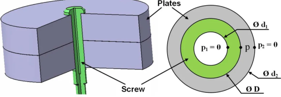
Figure 6. Analytical model
The model presented in Figure 6 takes account of the hole drilled in the axis of the screw for the experimental study (d1). As a first approximation, the screw can be
considered as being subjected to the tightening load, which induces a uniform tension state, and to radial pressure on the shank. Based on the results presented in figure 4, the normal pressure between the screw and the plates can be taken as constant all along the contact surface. Assuming that radial pressure induces a plane stress state, the contact pressure p can be calculated as a function of the interference level ∆ and the other material and geometrical properties. Moreover,
the proposed equation takes account of the decrease in the external diameter of the screw, due to the tightening load, so as to correct the interference level.
− − + + + − + − − ∆ = 1 2 1 2 2 1 2 1 2 2 2 2 2 2 2 2 2 1 2 0 1 1 4 ν ν π ν d D d D E D D d d D E D d D F E D p Eq 1
with E1,
ν
1 material properties of the screw,E2,
ν
2 material properties of the plates,D, d1, d2 diameters described in Figure 5
Thus, the loss of load under the screw head, ∆FV, and at the interface between
plates, ∆FP, can be calculated:
1 L D p f FP =
π
∆ Eq 2(
L1 L2)
D p f FV = + ∆ π Eq 3With L1 the thickness of the plate in contact with the nut and
L2 the thickness of the plate in contact with the screw head less the chamfer.
We know that the experimental data in section 6 only give the axial strain on the screw. In order to validate our approach, it would be interesting to also have an analytical evaluation of the axial strain on the inner diameter of the screw. By considering the effects of the axial load, the loss of load due to friction and the axial strain of a thick tube subjected to an external pressure, Lame’s equations give the following formula:
( )
(
2)
1 2 1 2 0 2 2 2 d D E D p x D p f F x − + − =π
π
ν
π
ε
Eq 4x=0 at the nut; x= L1+L2 at the beginning of the chamfer near the screw head.
4.1 Results of the case study
In a preliminary design stage, the axial loss of load would be directly calculated by using Eq. 1, 2 and 3, with the approximated initial friction factor and the
manufactured interference level. This would give in our case (with f=0.045 and ∆= 0.102mm): p= 262 MPa, ∆FV =23.0 kN and ∆FP = 11.6 kN.
Thus, the proposed analytical approach gives an accurate approximation of the axial loss of load along the screw despite the underestimation of the average radial pressure.
5. Sensitivity study
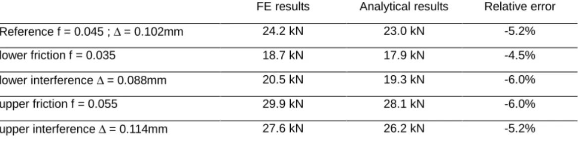
The objective is now to evaluate the influence of both the interference level ∆ and the friction factor f on the axial loss of load. The sensitivity study considers realistic potential evolutions of the parameters. Results are detailed in Table 1 for the axial load lost under the screw head and in table 2 for the load lost between plates. The results obtained by the finite element analysis (considered as our reference) are also compared to the ones obtained by the analytical approach.
Table 1. Sensitivity study on the load loss under the screw head
FE results Analytical results Relative error Reference f = 0.045 ; ∆ = 0.102mm 24.2 kN 23.0 kN -5.2% lower friction f = 0.035 18.7 kN 17.9 kN -4.5% lower interference ∆ = 0.088mm 20.5 kN 19.3 kN -6.0% upper friction f = 0.055 29.9 kN 28.1 kN -6.0% upper interference ∆ = 0.114mm 27.6 kN 26.2 kN -5.2%
Table 2. Sensitivity study on the load loss between plates
FE results Analytical results Relative error Reference f = 0.045 ; ∆ = 0.102mm 11.7 kN 11.6 kN -0.9% lower friction f = 0.035 9.1 kN 9.0 kN -0.4% lower interference ∆ = 0.088mm 9.9 kN 9.7 kN -1.8% upper friction f = 0.055 14.4 kN 14.2 kN -1.3% upper interference ∆ = 0.114mm 13.3 kN 13.2 kN -5.2%
In the variation domain considered, the sensitivity analysis shows that both the friction and the interference level have a great influence on the loss of load. Thus both have to be precisely determined in order to be able to evaluate the axial loss of load.
Moreover, the sensitivity study shows that, in our case study, the analytical
accuracy of about 1%. This is generally acceptable for designers in a preliminary design stage.
6. Experimental results
An experimental study was planned to measure the axial strain along the screw. It was therefore interesting to analyse the sensitivity of the axial strains obtained by the finite element approach in order to try to determine appropriate locations for the Bragg grating sensors
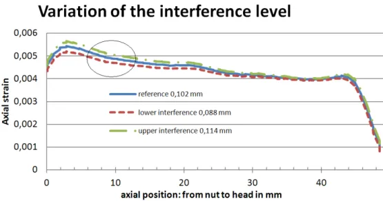
Figure 7. Sensitivity study on the interference level
Figure 8. Sensitivity study on the friction factor
Figures 7 and 8 show that the boundary effects at the beginning and end of the engagement make difficult to exploit sensors near x=0 mm and near x=49.5 mm.
The sensitivity study related to the interference level shows that this parameter has a major influence near the nut. In contrast, the sensitivity study on the friction factor shows that this parameter has a major influence near the screw head. Thus, a sensor placed near the nut (x=10 mm) should help to evaluate the interference level and another sensor placed near the screw head (x=36 mm) should help to evaluate the friction factor. This shows that screws equipped with at least two sensors may enable values of ∆ and f to be evaluated, and then the loss of load under the screw head to be assessed.
An experimental study was then performed to test the accuracy of the simulations. Three specimens based on the reference interference level were tested. In his study, Pran [18] satisfactorily used an optical fibre equipped with a single Bragg grating. In our study, we needed to measure the axial strain at two axial positions at least. For that reason and to increase confidence in the results, each specimen tested contained an optical fibre equipped with four Bragg gratings, each 3 mm long with a 7-mm axial pitch as illustrated in Figure 9.
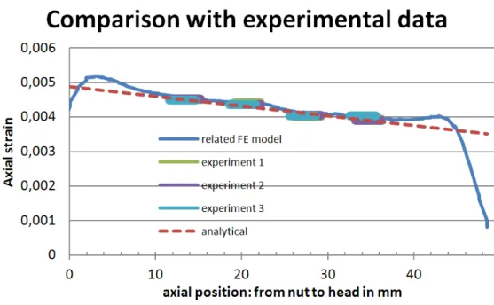
Figure 10. Comparison with experimental data
The interference level and the friction factor were adjusted by hand on the finite element model in order to fit the results given by the sensors. We finally obtained ∆=0.088 mm and f= 0.045. The results are presented in Figure 10.
They show that, in this case, the initial evaluation of the friction factor is very good but the interference level that is to be exploited in the simulation (∆=0.088 mm) has to be lower than the geometrical one for the experiments (∆=0.102 mm). This can be easily explained by the influence of roughness, which is not
considered in the proposed simulation as the contact between perfect cylindrical surfaces is simulated. The finite element simulation evaluates the average pressure
p = 220 MPa. Moreover, the tangential loads on the nodes on the shank are
exploited to evaluate the axial loss of load. This leads to ∆FV =20.5 kN and ∆FP =
9.9 N. These values are lower than the ones calculated for the reference case. Thus, in a preliminary design stage, using the initial values for f and ∆ for the finite element study would lead to an overestimate of the axial loss of load.
Figure 9 also presents the analytical curve obtained by finding the optimal values of f and p that minimize the gap between the results of eq 4 and experimental data. The optimal values are f = 0.0481 and p = 199.97 MPa.
The values are rather similar to the one obtained with the finite element analysis. Considering this, Eq. 2 and Eq. 3 enable the axial loss of loads to be evaluated:
∆FV =18.7 kN and ∆FP = 9.5 kN. These values are quite close to the ones obtained
with the finite element simulation. We can thus consider that the analytical approach gives acceptable results for evaluating the axial loss of load from experimental data.
Moreover, Eq 1 enables the interference level to be evaluated: ∆= 0.083 mm. The interference level is very close to the one estimated for the finite element
simulation (∆=0.088 mm). This shows that the accuracy of Eq. 1 can be considered as satisfactory.
7. Conclusions
The behaviour of an interference fit fastener has been analysed. The results show good agreement between experimental data and FE numerical results. In the case studied, the proposed analytical formulae are accurate enough to evaluate the axial loss of load from the measured axial strain.
The variations of the pressure on the shank of the screw have also been analysed. As expected, peaks are present at each contact edge. Pressure discontinuity at the interface between the plates has also been highlighted for the first time. A study of the influence of the interference level and the friction factor was then performed. It showed that both had a similar influence on the loss of load. The sensitivity study also showed that the interference level significantly influenced the axial strain near the nut and that friction significantly influenced the axial strain near the screw head.
These data were useful for defining accurate positions for the sensors. An
experimental study using optical fibres with four Bragg grating sensors each was then performed and enabled the practical friction factor and interference level to be evaluated.
We have shown that both the finite element simulation and the analytical models tend to overestimate the axial loss of load along the screw but that the accuracies look acceptable for use in a preliminary design stage.
8- References
[1] Petrak, G.J., Steward, R.P.: Retardation of cracks emanating from fastener holes. Eng. Frac. Mech. 6(2), 275-282 (1974).
[2] Chakherlou, T.N., Mirzajanzadeh, M., Vogwell, J.: Experimental and numerical investigations into the effect of an interference fit on the fatigue life of double shear lap joints. Eng. Fail. Ana. 16, 2066–2080 (2009).
[3] Duprat, D., Campassens, D., Balzano, M., Boudet, R.: Fatigue life prediction of interference fit fastener and cold worked holes. Int. J. of Fat. 18(8), 515-521 (1996).
[4] Li, G., Backman, D., Bellinger, N., Shis, G.: Numerical modeling of a single aluminium sheet containing an interference fit fastener. Can. Aero. and Space J. 51(4), 107-122 (2005).
[5] Fontaine, J.F., Siala, I.E.: Optimization of the contact surface shape of a shrinkage fit. J. of Mat. Proc. Techn. 74, 96-103 (1998).
[6] Fontaine, J.F., Siala, I.E.: Form defect influence on the shrinkage fit characteristics. Europ. of Mech., A/ Solids, 17(1): J. of Mat. Proc. Tech. 74, 107-119 (1998).
[7] Yang, G.M., Coquille, J.F., Fontaine, J.C., Lambertin, M.: Influence of roughness on
characteristics of tight interference fit of a shaft and a hub. Int. J. of Sol. and Struc. 38, 7691-7701 (2001).
[8] Yang, G.M., Coquille, J.F., Fontaine, J.C., Lambertin M.: Contact pressure between two rough surfaces of a cylindrical fit. J. of Mat. Proce. Tech. 123, 490-497 (2002).
[9] Ozel, A., Temiz, S., Aydin, M.D., Sen, S. Stress analysis of shrink-fitted joints for various fit forms via finite element method. Mat. and des. 26, 281-289 (2005).
[10] Booker, J.D., Truman, C.E.: A statistical study of the coefficient of friction under different loading regimes. J. of Phy. D: Appl. Phy. 41, 1-12 (2008).
[11] Pedersen, P.: On shrink Fit Analysis and Design. Comput. Mech. 37, 121-130 (2006). [12] Zhang, Y., McClain, B., Fang, X.D.: Design of interference fits via finite element method. In. J. of Mech. Sci. 42, 1835-1850 (2000).
[13] Barrot, A., Daidie, A., Ghosn, A.: A FE Global approach for dimensioning bolted joints in large slewing bearings: application to an industrial case. IDMME 2008, Beijing, Proceedings of the conference (2008).
[14] Zouhair, C., Daidie, A., Leray, D.: Screw behavior in large diameter slewing bearing
assemblies: numerical and experimental analyses. In. J. of Inter. Des. and Manuf. 1, 21-31 (2007). [15] Daidie, A., Chakhari, J., Zqhal, A.: Numerical model for bolted T-stubs with two bolt rows, Struc. Eng. and Mech. 26(3), 343-361 (2007).
[16] Alkatan, F., Stephan, P., Daidie, A., Guillot, J.: Equivalent axial stiffness of various
components in bolted joints subjected to axial loading. Fin. Elem. in Ana. and Des., 43(8), 589-598 (2007).
[17] Hay, H.D.: Bolt, stud or fastener having an embedded fibre optic bragg grating sensor for sensing tensioning strain, United States Patent,(1997).
[18] Pran, K., Farsund, O., Wang, G.: Fibre Bragg grating smart bolt monitoring creep in bolted GRP composite. Opt. Fib. Sens. Conf. Tech. Dig., OFS 2002, 15th, 431-434(2002).