Open Archive TOULOUSE Archive Ouverte (OATAO)
OATAO is an open access repository that collects the work of Toulouse researchers and
makes it freely available over the web where possible.
This is an author-deposited version published in :
http://oatao.univ-toulouse.fr/
Eprints ID : 17434
To link to this article : DOI : 10.1016/j.jnoncrysol.2016.12.030
URL :
http://dx.doi.org/10.1016/j.jnoncrysol.2016.12.030
To cite this version :
Bessaguet, Camille and Dantras, Eric and
Lacabanne, Colette and Chevalier, Mathieu and Michon, Guilhem
Piezoelectric and mechanical behavior of NaNbO3/PEKK lead-free
nanocomposites. (2017) Journal of Non-Crystalline Solids, vol. 459.
pp. 83-87. ISSN 0022-3093
Any correspondence concerning this service should be sent to the repository
administrator:
[email protected]
Piezoelectric and mechanical behavior of NaNbO
3
/PEKK
lead-free nanocomposites
C. Bessaguet
a,b,c, E. Dantras
b,⁎
, C. Lacabanne
b, M. Chevalier
a, G. Michon
caInstitut de Recherche Technologique (IRT) Saint Exupéry, 118 route de Narbonne, CS 44248, 31432, Toulouse cedex 4,France bPhysique des Polymères, Institut Carnot CIRIMAT, Université Paul Sabatier, 118 route de Narbonne, 31062, Toulouse cedex 09, France cInstitut Supérieur de l'Aéronautique et de l'espace, Institut Clément Ader, 3 rue Caroline Aigle, 31400 Toulouse, France
a b s t r a c t
Lead-free piezoelectric nanocomposites based on poly(ether ketone ketone) (PEKK) and sodium niobate (NaNbO3) particles were elaborated. The presence of submicronic particles does not influence the thermal
stabil-ity of the matrix so that no degradation phenomenon is observed before 500 °C. The conservative mechanical modulus G′ increases linearly with the NaNbO3fraction; this variation is well fitted by the Kerner model until
20 vol%. Such nanocomposites remain ductile. The polarizing field required for obtaining piezoelectric nanocom-posites is 12 kV·mm−1i.e. analogous with the one used for poling bulk ceramic. The value of the piezoelectric
coefficient (d33= 0.2 pC·N−-1for 20 vol% NaNbO3) is consistent with the Furukawa's model. This value is
ex-plained by the low PEKK permittivity. This low d33is counterbalanced by the piezoelectric voltage constant
(g33= 103·10−3Vm·N−1) which is higher than the one of classical piezoelectric ceramic like PZT or BaTiO .
Keywords:
Lead-free ceramic Piezoelectric nanocomposite Poly(ether ketone ketone) Sodium niobate
Dynamic mechanical analysis Permittivity
1. Introduction
The first extrinsic piezoelectric composite has been elaborated in 1976 by Furukawa. Micronic electroactive particles of lead zirconate ti-tanate (PZT) have been dispersed in a polyepoxy matrix[1]. This kind of particles has been widely used subsequently, especially for applications of sensors and actuators due to a high Curie temperature and a high pi-ezoelectric coefficient[2–6]. However, the recent legislation about lead toxicity[7]has highly stimulated the use of lead-free ceramic such as barium titanate (BaTiO3)[8–12], potassium niobate (KNbO3)[13–15], lithium niobate (LiNbO3)[16,17], and sodium niobate (NaNbO3)[13, 18–20].
The interest of this study is the integration of the piezoelectric prop-erty using a lead-free piezoelectric ceramic in a structural polymer for aeronautical and space applications. Carponcin et al.[5]have studied the integration of PZT in poly(ether ether ketone) (PEEK). They showed that it was possible to disperse homogeneously electroactive particles in a high-performance thermoplastic matrix to bring it piezoelectric prop-erty. In this paper, the host matrix is the poly(ether ketone ketone) (PEKK), a high performance thermoplastic polymer also belonging to the poly(aryl ether ketone) (PAEK) family. PEKK has a melting temper-ature lower than PEEK making it less expensive for industrial process-ing. The lead-free selected electroactive ceramic was the NaNbO3. It
has a high Curie temperature (Tc) compatible with the matrix[21–23] and an interesting bulk piezoelectric coefficient (d33)[24,25]. The main challenge in piezoelectric composite processing is the polarization step. It is a critical step which is essential to obtain a piezoelectric mate-rial. It consists in applying an electric field (higher than the coercive field of the piezoelectric element) through the sample in order to orient the electric dipoles. Another advantage of NaNbO3is its low coercive field[26]and therefore it requires a low polarization field that limits the risk of breakdowns[27].
The present paper describes the synthesis and the characterization of NaNbO3. Then, the elaboration and polarization protocol are present-ed. We will focus on the influence of NaNbO3particles on thermal stabil-ity, mechanical and electroactive properties of PEKK/NaNbO3 nanocomposites.
2. Materials and methods
2.1. NaNbO3submicronic particles elaboration
NaNbO3particles were synthesized for the first time by Goh et al. [13]in 2003 using a hydrothermal synthesis. The structural evolution of NaNbO3during the reaction was studied more precisely by Zhu et al.[18]. First, fine powders aggregate to form irregular bars that grow into nanowires and finally submicronic particles. In this work, the David et al.[27]protocol, based on Goh's one, has been used. Niobi-um pentoxide (Nb2O5) and concentrated sodium hydroxide (10 M)
⁎ Corresponding author.
E-mail address:[email protected](E. Dantras).
were mixed in an autoclave and heated above 150 °C. The white com-pound obtained (Na2Nb2O6.2/3H2O) was filtered out, washed with de-ionized water and dried in an oven at 100 °C. NaNbO3particles were obtained after an annealing at 600 °C for 6 h.
2.2. PEKK/NaNbO3nanocomposite elaboration process
Ceramic particles were milled with a mortar in order to break any aggregates. They were dispersed in ethanol with ultrasound and mixed with the polymer powder. After ethanol evaporation, the PEKK/ NaNbO3nanocomposite powder was homogeneous. PEKK/NaNbO3 mix was processed using a twin screw extruder at 360 °C during 15 min at 30 rpm. Nanocomposites with different volume fractions were elaborated from 3% to 30% in volume fraction.
Fig. 1represents a scanning electron microscopy (SEM) micro cut of PEKK/NaNbO320 vol% sample. Particle dispersion in the polymer matrix was homogeneous at this scale. Dispersion quality is an important pa-rameter to facilitate the polarization process and prevent from electrical breakdowns.
2.3. Polarization process
The polarization process consists in orienting electric dipoles to ob-tain a macroscopic piezoelectric effect[10]. The material was inserted under a high static electric field at a given isotherm. During the cooling, the electric field was maintained in order to fix the dipole orientation. Polarization temperature, electric field value and poling time were optimized.
The following Eq.(1)makes the link between the field really seen by the particles E!P, the matrix and particle permittivities, εMand εP respec-tively, and the applied electric field E!appl[8].
Ep
!! ¼ 3εM εpþ 2εM
Eappl
!!! ¼ LEE!!!appl ð1Þ
To optimize E!P(and therefore the polarization efficiency), the ratio between matrix and particle permittivity is crucial. A dynamic dielectric analysis was performed on the PEKK in order to determine the evolution of the matrix permittivity as a function of temperature. Above the di-electric manifestation of the glass transition (Tα), εMincreases; it is suit-able for the polarization. Thus, the polarization was performed at a temperature higher than Tα(Tpol≈ 180 °C) under an electric field higher than the coercive field (Epol≈ 12 kV·mm−1) during 15 min. To avoid
breakdowns and to optimize the isotherm quality, samples were im-mersed in an oil bath. After the polarization process, nanocomposites were short-circuited during 24 h and the piezoelectric coefficient (d33) was measured.
3. Experimental
Thermogravimetric analysis (TGA Q50 from TA instruments with an accuracy of ± 1 wt%) was performed under air atmosphere at 20 °C·min−1to measure the nanocomposites thermal stability and de-termine the experimental volume fraction of sodium niobate. The phys-ical structure, as the glass transition, the crystallinity rate and the melting temperatures, was determined by differential scanning calo-rimetry (DSC) using a DSC7 from Perkin Elmer with a temperature accu-racy of ± 0.1 °C and an enthalpy accuaccu-racy of ± 0.2 J·g− 1. The crystallinity rate was determined by normalizing the matrix fraction. To study nanocomposites mechanical properties, dynamical mechanical analysis (DMA, ARES) was performed in rectangular mode. The applied deformation and angular frequency were fixed at 0.1% and 1 rad·s−1 re-spectively. The particle morphology and the particle dispersion quality were observed using a scanning electron microscope (MEB-FEG JEOL JSM 7800F Prime) using secondary and backscattered electron detec-tion. After the nanocomposites polarization (see “polarization process” section), the piezoelectric coefficient (d33) was measured using a Pie-zometer system from Piezotest with frequency and force of 110 Hz and 0.25 N respectively.
4. Results
4.1. NaNbO3analysis
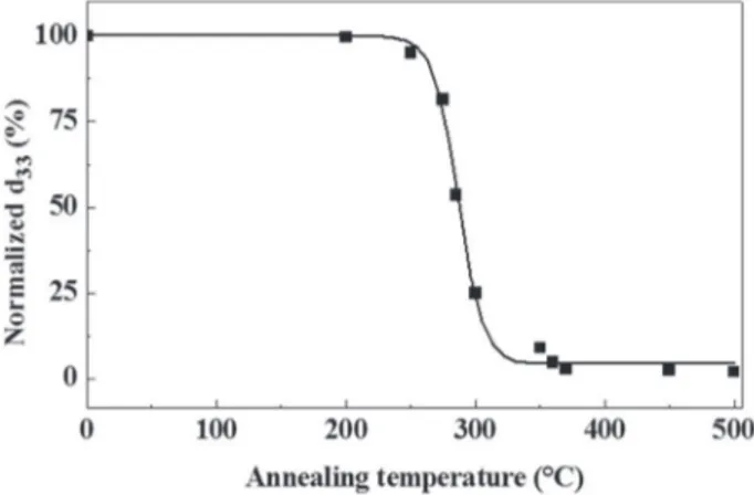
Inset ofFig. 1represents SEM image of NaNbO3particles. They were cubic with a low aspect ratio. The particle size was about 1 μm. Due to a high Curie temperature (Tc) and a weak modification of crystalline lat-tice parameters, conventional techniques as DSC or x-ray diffraction (DRX) could not be used to determine Tc. A non-classical protocol has been developed: A ceramic disk was manufactured by spark plasma sintering (SPS) to limit the grain growth, polarized under a static field and annealed at different temperatures until Curie transition. The max-imum d33was measured at 34.5 pC·N−1which is coherent with the lit-erature[25,28].
Fig. 2represents the d33evolution as a function of annealing temper-ature. Tcwas measured at 287 °C.
4.2. Thermal stability
Fig. 3shows the weight loss as a function of temperature for nano-composites with different NaNbO3 volume fraction. Under air
Fig. 1. SEM image of PEKK/NaNbO3micro cut with a volume fraction of 20% (scale bar:
10 μm). In the insert: NaNbO3particles (scale bar: 1 μm).
Fig. 2. d33evolution of NaNbO3disk versus annealing temperature. The line is drawn as a
atmosphere, above 750 °C, PEKK was totally degraded. The weight res-idue corresponds directly to the weight fraction of particles. The exper-imental volume fraction of NaNbO3is calculated from the residue at 900 °C. The degradation temperature (Td) is measured at the peak max-imum of the weight loss derivate curve. Inset ofFig. 3represents the evolution of Tdas a function of NaNbO3volume fraction. Until 6 vol%,
Tdis stable. It appears that for higher fractions, Tddecreases when the fraction of NaNbO3increases.
4.3. Physical structure
Nanocomposites physical structure has been studied.Fig. 4shows the evolution of the melting temperature and crystallinity ratio as a function of NaNbO3volume fraction.
The melting temperature and the crystallinity ratio decrease linearly. Particles do not promote crystallinity and reduce the cohesion of the crystal. In addition, presence of particles does not change the glass tran-sition temperature which means that NaNbO3particles do not affect the chain mobility or the free volume of the amorphous phase.
4.4. Mechanical properties
Fig. 5shows the evolution of conservative G′ and dissipative G″ mod-ulus of the neat PEKK over a wide range of temperature. G″ highlights 3 relaxation modes[29,30]: α mode at 165 °C is associated with the
mechanical manifestation of the glass transition, β mode between − 60 °C and 0 °C, with the oscillation of the aromatic rings around the main chain and finally, the localized γ mode between −130 °C and − 60 °C highlights the interaction between ketone functions and absorbed water.
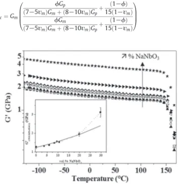
The evolution of the vitreous modulus of PEKK/NaNbO3 nanocom-posites is presented inFig. 6as a function of temperature for different volume fraction of NaNbO3. The value of the vitreous plateau increases with the introduction of NaNbO3, from 1.5 GPa to 3.7 GPa at 20 °C. Inset ofFig. 6represents G′ measured at Tα-50 °C as a function of NaNbO3volume fraction.
It increases linearly until 20 vol%. To explain the critical increase of G′ for the last nanocomposite experimental data were fitted with the Kerner model (solid line). It is based on the hypothesis that spherical particles (or particles with a low aspect ratio) without interaction, are randomly dispersed in the matrix. Nanocomposite conservative modu-lus is given by the Eq.(2) [31]:
Gc¼ Gm ϕGp 7−5υm ð ÞGmþ 8−10υð mÞGpþ 1−ϕ ð Þ 15 1−υð mÞ ϕGm 7−5υm ð ÞGmþ 8−10υð mÞGpþ 1−ϕ ð Þ 15 1−υð mÞ 0 B B @ 1 C C A ð2Þ
Fig. 3. TGA thermogram of PEKK and PEKK/NaNbO3: (■) PEKK, ( ) PEKK/NaNbO34 vol%,
(▲) PEKK/NaNbO36 vol%, ( ) PEKK/NaNbO39 vol%, (♦) PEKK/NaNbO310 vol%, ( ) PEKK/
NaNbO311 vol%, (►) PEKK/NaNbO320 vol%, ( ) PEKK/NaNbO330 vol%. In the inset:
evolution of the degradation temperature versus the experimental vol% of NaNbO3.
Fig. 4. Melting temperature (■) and crystallinity ratio ( ) versus NaNbO3vol% for PEKK/
NaNbO3nanocomposites during the 2nd run.
Fig. 5. Evolution of the conservative G′ (▲) and dissipative G″ ( ) modulus of PEKK versus temperature.
Fig. 6. Real part of the shear modulus (■) versus temperature of PEKK and PEKK/NaNbO3:
(■) PEKK, ( ) PEKK/NaNbO34 vol%, (▲) PEKK/NaNbO36 vol%, ( ) PEKK/NaNbO39 vol%,
(♦) PEKK/NaNbO310 vol%, ( ) PEKK/NaNbO311 vol.%, (►) PEKK/NaNbO320 vol%, ( )
PEKK/NaNbO330 vol%. In the inset: value of the vitreous plateau measured at Ta-50 °C
where Gc, Gmand Gpare respectively the shear modulus of nanocompos-ites, matrix and particles, υmis the Poisson coefficient and ϕ is the vol-ume fraction of particles.
Until 20 vol% experimental data are fitted well with this model. Thus, hypotheses are verified. For the nanocomposite with 30 vol% of NaNbO3, the experimental mechanical values depart from the model prediction. The evolution of the dissipative modulus G″ of PEKK/NaNbO3 nano-composites as a function of temperature related to the α mode is pre-sented inFig. 7for different volume fraction of NaNbO3. The area under the curve (noted as αPEKKand αPEKK/NaNbO3for PEKK and its nano-composites respectively) represents the energy dissipated by the poly-mer matrix due to the viscoelastic relaxation. Inset ofFig. 7represents the specific energy loss normalized by the matrix fraction as a function of NaNbO3volume fraction. Presence of ceramic particles leads to an in-crease of the dissipated energy. The same shift is observed for β and γ modes at the same temperatures.
4.5. Piezoelectric properties
d33coefficient of nanocomposites was measured 24 h after the po-larization step.Fig. 8a) represents the evolution of d33as a function of NaNbO3 volume fraction. Experimental data were fitted with the Furukawa's model[2](solid line inFig. 8a) according to the following Eq.(3):
d33¼ ϕLEd33incl ð3Þ
where d33is the piezoelectric coefficient of nanocomposites, ϕ the volume fraction of NaNbO3, LEthe local field applied[8]and d33inclthe intrinsic piezoelectric coefficient of bulk NaNbO3.
This model considers a 2-phases system composed of a non-piezoelectric continuous phase where non-piezoelectric particles are ran-domly dispersed.
From 8 vol%, the variation of d33is quasi-linear and experimental data are closed to the expected values. Particles are well dispersed into the matrix until 20 vol%.
In addition to the d33, the piezoelectric voltage constant g33is anoth-er piezoelectric parametanoth-er given by the following Eq.(4) [27]:
g33¼d33
εM ð4Þ
For bulk piezoelectric ceramic, d33and εMare both high. For organic polymer where piezoelectric ceramics are dispersed, d33is low. But it is counterbalanced by a very low matrix permittivity.Fig. 8b) shows the evolution of g33with the NaNbO3volume fraction. The low matrix per-mittivity leads to a high value of g33(g33(PEKK/30 vol% NaNbO3= 104·10−3Vm·N−1).
5. Discussion
5.1. Curie temperature measurement
Literature reports values from 180 °C to 370 °C for the Tcof NaNbO3. The discrepancy obtained could be explained by poly crystallinity and/ or particle size. Most of the time, Tcmeasurements were performed on mono crystals[21]. Hydrothermal synthesis tends to promote poly crys-tals. Furthermore, Moure et al.[22]show the influence of particle size on
Tc. Particles with size higher than 1 μm have a Tcat 370 °C. For particles with a size between 200 and 400 nm, Tcranges from 310 °C to 330 °C and finally for particle size lower than 70 nm, Tcis measured at 180 °C. In this work, a size distribution probably exists and could explain the low value of Tc.
5.2. Conservative and dissipative modulus
For the nanocomposite with 30 vol% of NaNbO3, experimental data of conservative modulus depart from the model prediction (Kerner model). This is due to a change of the composite connectivity from 0– 3 to 3–3[32]that probably suppose a contact between particles and therefore critical modifications of the mechanical properties.
The increase of the dissipated energy (calculated from the area under the dissipative modulus) with the introduction of particles could be due to a friction phenomenon called “stick slip” at the interface between stiff particles and soft matrix[33]. In addition, it is interesting
Fig. 7. Imaginary part of the shear modulus (■) versus temperature of PEKK and PEKK/ NaNbO3: (■) PEKK, ( ) PEKK/NaNbO34 vol%, (▲) PEKK/NaNbO36 vol%, ( ) PEKK/
NaNbO39 vol%, (♦) PEKK/NaNbO310 vol%, ( ) PEKK/NaNbO311 vol%, (►) PEKK/
NaNbO3 20 vol%, ( ) PEKK/NaNbO3 30 vol%. In the inset: specific energy loss
normalized by the matrix fraction versus vol%.
Fig. 8. Evolution of the piezoelectric coefficient d33(■) fitted with the Furukawa's model (solid line) a) and the piezoelectric voltage constant g33( ) b) of PEKK/NaNbO3versus NaNbO3
to note that mode temperatures are not modified by the introduction of NaNbO3, so the molecular mobility is unchanged by the presence of particles.
5.3. Piezoelectric coefficients
For the PEKK/NaNbO330 vol%, experimental data diverge from the Furukawa model. The change of connectivity also affects the piezoelec-tric property. However, the d33values obtained are low. Particle and matrix permittivities have a strong influence on the polarization effi-ciency. On the one hand, a PVDF/20 vol% NaNbO3nanocomposites was elaborated with the same process and polarized. Its d33is higher (3.95 pC·N−1) (seeFig. 8a) due to the higher permittivity of the PVDF (12 for PVDF, 2.7 for PEKK at RT). This value is coherent with the d33value predicted by Furukawa's theoretical model. On the other hand, the in-fluence of the particle intrinsic d33is important. To give an example PEEK/PZT 30 vol% nanocomposite has a d33of 1.95 pC·N−1[5]due to a high d33of PZT (240 pC·N−1)[34].
Nevertheless, g33(PEKK/30 vol% NaNbO3) is higher than common piezoelectric ceramics like BaTiO3(g33(BaTiO3) = 11·10−3Vm·N− 1) or PZT (g33(PZT) = 52·10−3Vm·N−1).
6. Conclusion
Piezoelectric nanocomposites were elaborated using a high perfor-mance thermostable thermoplastic polymer and a lead-free piezoelec-tric ceramic. Submicronic NaNbO3was synthesized via a hydrothermal synthesis. The dispersion process leads to a good dispersion of particles in the PEKK. Particles do not influence the thermal stability of matrix: no degradation is observed before 500 °C. Melting temperature and crystallinity rate decrease with the NaNbO3volume fraction. As for mechanical properties, the value of the vitreous plateau generates an increase of the nanocomposite rigidity. We observe a stick-slip phe-nomenon that increases the dissipated energy related to the viscoelas-tic relaxation when the parviscoelas-ticle fraction increases. Polarization is a critical step due to high temperature and high electric field required. The piezoelectric coefficient increases with the ceramic particles con-tent but remains low due to low matrix permittivity. For other applica-tions, the d33could be improved with matrix of higher permittivity. It is important to note that the piezoelectric voltage constant g33 is higher than for common inorganic piezoelectric ceramic like PZT or BaTiO3.
Acknowledgments
These results were obtained under the research project “COMPINNOVTP” at the IRT Saint Exupéry. We thank the industrial and academic members of the IRT who supported this project through their contributions, both financial and in terms of specific knowledge:
- Industrial members: AIRBUS OPERATIONS, AIRBUS DEFENCE & SPACE, AIRBUS HELICOPTERS, AIRBUS GROUP INNOVATIONS and THALES ALENIA SPACE
- Academic members: CIRIMAT, ISAE, ICA, IMRCP, UPS and CNRS We also thank the Commissariat Général aux Investissements and the Agence Nationale de la Recherche for their financial support in the Programme d'Investissement d'Avenir (PIA).
References
[1] T. Furukawa, K. Fujino, E. Fukada, Electromechanical properties in the composites of epoxy resin and PZT ceramics, Jpn. J. Appl. Phys. 15 (1976) 2119–2129. [2] T. Furukawa, K. Ishida, E. Fukada, T. Furukawa, K. Ishida, E. Fukada, Piezoelectric
properties in the composite systems of polymers and PZT ceramics, J. Appl. Phys. 50 (1979) 4904–4912.
[3] A. Jain, K.J. Prashanth, A.K. Sharma, A. Jain, P.N. Rashmi, Dielectric and piezoelectric properties of PVDF/PZT composites: a review, Polym. Eng. Sci. (2015) 1589–1616. [4] V. Tiwari, G. Srivastava, Structural, dielectric and piezoelectric properties of 0–3 PZT/
PVDF composites, Ceram. Int. 41 (2015) 8008–8013.
[5] D. Carponcin, E. Dantras, L. Laffont, J. Dandurand, G. Aridon, F. Levallois, L. Cadiergues, C. Lacabanne, Integrated piezoelectric function in a high thermostable thermoplastic PZT/PEEK composite, J. Non-Cryst. Solids 388 (2014) 32–36. [6] S. Touhtouh, M. Rguiti, C. Courtois, F. Belhora, A. Arbaoui, S. Dastorg, A. Rachek, A.
Hajjaji, PU/PZT composites for vibratory energy harvesting, Opt. Quant. Electron. 48 (2016) 246.
[7] Directive 2002/95/EC of the European Parliament and of the Council of the European Union, Off. J. Eur. Union 37 (2003) 19–51.
[8] H.L.W. Chan, M.C. Cheung, C.L. Choy, Study on BaTiO3/P(VDF-TrFE) 0-3 composites, Ferroelectrics 224 (1999) 113–120.
[9] J. Yuh, J.C. Nino, W.M. Sigmund, Synthesis of barium titanate (BaTiO3) nanofibers via
electrospinning, Mater. Lett. 59 (2005) 3645–3647.
[10] J.F. Capsal, E. Dantras, L. Laffont, J. Dandurand, C. Lacabanne, Nanotexture influence of BaTiO3particles on piezoelectric behaviour of PA 11/BaTiO3nanocomposites, J.
Non-Cryst. Solids 356 (2010) 629–634.
[11] M.D. Toomey, K. Gao, G.P. Mendis, E.B. Slamovich, J.A. Howarter, Hydrothermal syn-thesis and processing of barium titanate nanoparticles embedded in polymer films, ACS Appl. Mater. Interfaces 7 (2015) 28640–28646.
[12] S. Dalle Vacche, Y. Leterrier, V. Michaud, D. Damjanovic, A.B. Aebersold, J.A.E. Manson, Effect of interfacial interactions on the electromechanical response of poly(vinylidene fluoride-trifluoroethylene)/BaTiO3composites and its time
depen-dence after poling, Compos. Sci. Technol. 114 (2015) 103–109.
[13]G.K.L. Goh, F.F. Lange, S.M. Haile, C.G. Levi, Hydrothermal synthesis of KNbO3and
NaNbO3powders, J. Mater. Res. 18 (2003) 338–345.
[14] K.I. Kakimoto, I. Masuda, H. Ohsato, Lead-free KNbO3piezoceramics synthesized by
pressure-less sintering, J. Eur. Ceram. Soc. 25 (2005) 2719–2722.
[15]T. Shiraishi, N. Kaneko, M. Ishikawa, M. Kurosawa, H. Uchida, H. Funakubo, Ferro-electric and piezoFerro-electric properties of KNbO3films deposited on flexible organic
substrate by hydrothermal method, Jpn. J. Appl. Phys. 53 (2014).
[16] D.G. Lim, B.S. Jang, S.I. Moon, C.Y. Won, J. Yi, Characteristics of LiNbO3memory
ca-pacitors fabricated using a low thermal budget process, Solid State Electron. 45 (2001) 1159–1163.
[17]W. Weng, H. Wang, N. Ma, Y. Wu, J. Li, Effect of domain structure on the damping properties of LiNbO3/Al composites, Mater. Des. 31 (2010) 4116–4121.
[18] H. Zhu, Z. Zheng, X. Gao, Y. Huang, Z. Yan, J. Zou, H. Yin, Q. Zou, S.H. Kable, J. Zhao, Y. Xi, W.N. Martens, R.L. Frost, Structural evolution in a hydrothermal reaction between Nb2O5and NaOH solution: from Nb2O5grains to
micropo-rous Na2Nb2O62/3 H2O fibers and NaNbO3cubes, J. Am. Chem. Soc. 128
(2006) 2373–2384.
[19] H. Song, W. Ma, Hydrothermal synthesis of submicron NaNbO3powders, Ceram. Int.
37 (Apr. 2011) 877–882.
[20] H.B. Kang, C.S. Han, J.C. Pyun, W.H. Ryu, C.-Y. Kang, Y.S. Cho, (Na,K)NbO3
nanoparticle-embedded piezoelectric nanofiber composites for flexible nanogenerators, Compos. Sci. Technol. 111 (2015) 1–8.
[21] Y.I. Yuzyuk, P. Simon, E. Gagarina, L. Hennet, D. Thiaudière, V.I. Torgashev, S.I. Raevskaya, I.P. Raevskii, L.A. Reznitchenko, J.L. Sauvajol, Modulated phases in NaNbO3: Raman scattering, synchrotron x-ray diffraction, and dielectric
investiga-tions, J. Phys. Condens. Matter 17 (2005) 4977–4990.
[22] A. Moure, T. Hungría, A. Castro, L. Pardo, Microstructural effects on the phase tran-sitions and the thermal evolution of elastic and piezoelectric properties in highly dense, submicron-structured NaNbO3 ceramics, J. Mater. Sci. 45 (2009)
1211–1219.
[23] Y. Yoneda, D. Fu, S. Kohara, Local structure analysis of NaNbO3, J. Phys. Conf. Ser. 502
(2014) 012022.
[24] A. Moure, T. Hungría, A. Castro, L. Pardo, Quantitative microstructural analysis and piezoelectricity of highly dense, submicron-structured NaNbO3ceramics from
me-chanically activated precursors, J. Eur. Ceram. Soc. 29 (2009) 2297–2308. [25]H. Ge, Y. Hou, C. Xia, M. Zhu, H. Wang, H. Yan, Preparation and piezoelectricity of
NaNbO3high-density ceramics by molten salt synthesis, J. Am. Ceram. Soc. 94
(2011) 4329–4334.
[26]T. Wada, K. Tsuji, T. Saito, Y. Matsuo, Ferroelectric NaNbO3ceramics fabricated by
spark plasma sintering, Jpn. J. Appl. Phys. 42 (Part 1) (2003) 6110–6114. [27]C. David, J.-F. Capsal, L. Laffont, E. Dantras, C. Lacabanne, Piezoelectric properties of
polyamide 11/NaNbO3nanowire composites, J. Phys. D. Appl. Phys. 45 (2012)
415305.
[28] H. Pan, G. Zhu, X. Chao, L. Wei, Z. Yang, Properties of NaNbO3powders and ceramics
prepared by hydrothermal reaction, Mater. Chem. Phys. 126 (2011) 183–187. [29] T. Sasuga, M. Hagiwara, Molecular motions of non-crystalline poly(aryl
ether-ether-ketone) PEEK and influence of electron beam irradiation, Polymer 26 (1985) 501–505.
[30] L. David, S. Etienne, Molecular mobility in para-substitued polyaryls. 1. Sub-Tg relax-ation phenomena in poly(aryl ether ether ketone), Macromolecules 25 (1992) 4302–4308.
[31]E.H. Kerner, The elastic and thermo-elastic properties of composite media, Proc. Phys. Soc. Sect. B. 69 (2002) 808–813.
[32]R.E. Newnham, D.P. Skinner, L.E. Cross, Connectivity and piezoelectric-pyroelectric composites, Mater. Res. Bull. 13 (1978) 525–536.
[33] C. Iurian, F. Ikhouane, J.J. Rodellar Benedé, R. Griñó, Identification of a System With Dry Fiction, Reports Recer. l'Institut d'Organització i Control Sist. Ind, 1, 2005. [34] W. Margaret, Sodium Potassium Niobate Based Piezoelectric Ceramics, University of