OATAO is an open access repository that collects the work of Toulouse
researchers and makes it freely available over the web where possible
Any correspondence concerning this service should be sent
to the repository administrator:
[email protected]
This is an author’s version published in: http://oatao.univ-toulouse.fr/27006
To cite this version:
Catry, Romain and Mohand-Ousaid, Abdenbi and Rakotondrabe,
Micky
and Lutz, Philippe Presentation, modeling and
experiments of an electrostatic actuator based catom for
programmable matter. (2020) MDPI Actuators, 9 (2). 43.
Official URL:
Article
Presentation, Modeling and Experiments of an
Electrostatic Actuator Based Catom for
Programmable Matter
Romain Catry1, Abdenbi Mohand-Ousaid1, Micky Rakotondrabe2,* and Philippe Lutz1
1 Department of Automatic Control and Micro-Mechatronic Systems, FEMTO-ST Institute,
Université Bourgogne Franche-Comté, CNRS, 24 rue Savary, 25000 Besançon, France;
[email protected] (R.C.); [email protected] (A.M.-O.); [email protected] (P.L.)
2 Laboratoire Génie de Production, National School of Engineering in Tarbes (ENIT-INPT),
University of Toulouse, 47 Avenue d’Azereix, 65000 Tarbes, France
* Correspondence: [email protected]
Received: 9 May 2020; Accepted: 29 May 2020; Published: 4 June 2020
Abstract:Nowadays, the concept of programmable matter paves the way for promising applications such as reshaping an object to test different configurations, modeling or rapid prototyping. Based on elementary modules, such matter can be arranged and disassembled easily according to the needs of the designers. Several solutions have been proposed to implement this concept. Most of them are based on modular self-reconfigurable robotics (SMR) that can work together and move relatively to one another in order to change their configuration. Achieving such behavior requires to solve some technological challenges in particular module’s geometry and actuation. In this paper, we build and develop a proof of concept for a catom based on electrostatic actuation. The modeling and analysis of the actuator functioning as catom is given after a comparison of various possible actuation. Simulations as well as experiments validations are afterwards carried out to confirm and demonstrate the efficiency of electrostatic actuation to achieve latching capabilities of the proposed catom.
Keywords:electrostatic actuation; programmable matter; self-reconfigurable robotics
1. Introduction
1.1. Programmable Matter
Programmable matter is a term that was first defined by Toffoli and Margolus [1] to refer to an ensemble of fine grained computing elements arranged in space. It is a matter that can change its properties such as shape, optical properties, color, conductivity, density, and so forth. on demand from a user, from sensor feeds or from software control. A best conceptual illustration of this matter is the fictional T1000 liquid-metal robot from the James Cameron film-Terminator 2: Judgment day [2]. The robot’s body, composed of billions of microscopic modules, has the capacity to reconstitute itself after an injury.
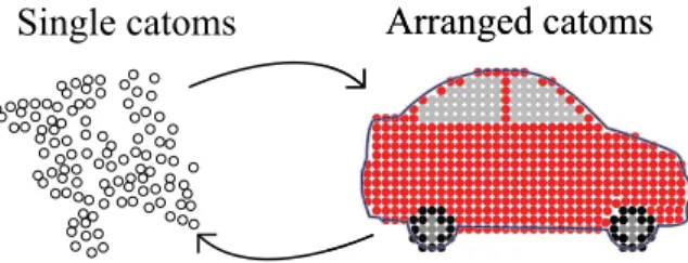
One advantage of programmable matter is its morphability which could allow to send or copy objects as easily as digital documents. For example, reshaping an object to test different configurations allows for cheap and rapid prototyping for car manufacturers or plane designers. As described in Figure1, the modules composing the programmable matter (on the left) can be rearranged to form a car model (on the right). Once the model is validated by designers, they can be disassembled for another use. In an industrial world where time, money and recycling are feature keys, such morphability is a very interesting concept.
Figure 1.Illustration of programmable matter used for car prototyping unit.
From physical point of view, implementing programmable matter concept is challenging and remains an active research area. Several solutions have been proposed in the literature. Almost all of them are based on modular self-reconfigurable robotics (MSR) which has the advantage of including a computation part. These solutions are composed of individual modules (one or several kind) that have to satisfy the three following properties—Latching, Locomotion, and Communication. Then an algorithm has to overview all the catoms to allow them to arrange their configuration and to reach the desired shape. This paper will study and design one catom that with a focus on the first property: the latching capabilities. In the rest of this introduction-section, we first give a state of the art of programmable matter in MSR approach. Then we compare the different actuation technologies from which we will justify the use of electrostatic actuators in our case. Finally, we present the contribution of the paper.
1.2. State of the Art
In the field of programmable matter and self-reconfigurable robotic systems, there are a lot of works in the literature. Toffoli and Margolus [1] introduced the concept of programmable matter. Later on, roboticists started from this concept in order to go towards physical realization. Fukuda et al. [3] developed the CEBOT (Cellular Robot) and set a base for most of the following works. Many prototypes have been created since then, in a large scope of size, shapes, in both 2D and 3D configurations. While most of the existing systems exploit a lattice structure to lessen the complexity of self-reconfiguration, there also exist chain type systems which do not rely on a lattice. However, these two types do not negate each other and some existing systems are even based on both at the same time such as the M-TRAN (Self-reconfigurable modular robot) [4].
An MSR module has generally to be fast when in movement and has to exhibit a strong latching capability when in rest, and if possible exhibits energy efficiency property. The M-block modules in Reference [5] offer an answer to these requirements by using cubic robots shape able to move thanks to inertial motors and to latch to each other using permanent magnets. They are one of the most advanced modules on the market that can claim to be programmable matter. Their permanent magnets offer strong latching capability, which is very useful to oppose gravity and to stack lots of modules at once. Indeed, gravity is one of the biggest challenge to deal with when working in the 3D MSR. In Reference [6], the authors proposed modules based on helium robots such that the gravity is overcomed. On the other hand, Garcia et al. [7] worked with pneumatic energy to latch their modules. While there was no real actuation, their vacuum powered robots have a very strong latching capability. Such latching strength is one of the most important part regarding programmable matter because the modules have to uphold the desired form when all of them are connected. The Molecule [8] is a set of two modules attached each other by a rigid axis. Each pair of modules can then connect with the other pairs and move around. A lot of robots also use mechanical latching for its strong force generation capability beyond the fact that it is a well known principle. A wide variety of approaches based on mechanical latching exists nowadays. For instance 3D-Units [9] and the ATRON (lattice based self-reconfigurable robot) [10] are based on hooks, whilst the Metamorphic modules in Reference [11] are based on key and locks. Even if lattice based-systems are predominant, one can also find chained based systems in the literature, such as the CONRO (Configurable Robots) [12] or the Modular-Expanding modules [13].
The above survey are related to 3D modules. However, the design of a 3D module can also be inspired from their 2D counterpart, in particular in term of actuation principle. The 2D Claytronic cylinder presented in [14] uses an electrostatic actuation which serves as both latching and movement generation. Though not widely used, the advantage of electrostatic actuation is its miniaturization possibility. In [15], an electromagnetic actuation is used for latching. While one module cannot move relatively to another one, the feature was that they can communicate each other through electromagnetic field In Reference [16], the above electromagnetic actuation for latching has been extended to 3D modules. Yim et al. [2] and Ostergaard et al. [17] provide much more thorough review on modula robotics that can be extended to modules for programmable matter. Overall, most of the current technologies regarding programmable matter favor cube-shaped modules since they offer several advantages: large surfaces for easier latching, ease of fabrication, and high stability when stacked/latched. In counterpart, these advantages are at the expense of the difficulty to create relative movement between modules.
1.3. Comparison of Different Actuation Technologies
To compare the different potential technologies used in modules, we propose the following measures:
• force generated by a module (Latching force), • energy required for latching (Energy), • miniaturization possibility (Miniaturization),
• ease of integration of the actuation on a module (Integration),
• and possibility to use the same latching actuation for relative movement (Movement).
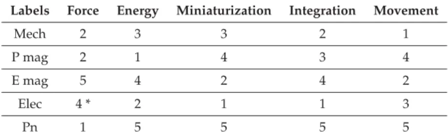
Table1provides the ranking of the different principles of module latching found in the literature: mechanical latching (Mech), permanent magnet latching (P mag), electromagnetic latching (E mag), electrostatic latching (Elec) and pneumatic latching (Pn). As already stated above, the mechanical latching is one of the most present in current technologies of modules because it is well understood, generates a strong force output and is relatively easy to integrate (mostly for cubic modules). In counterpart mechanical latching is not easy to miniaturize and its energy consumption is relatively high. Permanent magnet latching also suffers from miniaturization limitation. Moreover, it is not adapted as actuation for relative movement between modules because of the strong stuck force they produce and that keep the latters latched, and because the fact that they are not really controllable. On the other hand, electromagnetic actuation is controllable versus permanent magnet actuation. However it requires high current. Beyond that, its main limitation is the very weak force when going to miniaturization. As from Table1, electrostatic actuation could provide the best compromise about the different criteria we impose to design modules for latching perspective. Even though electrostatic actuation produces less force compared to a mechanical latching or a permanent magnet, it has three main advantages. First, it requires small amounts of energy to ensure the latching. Indeed, electrostatic actuation might require high fixed voltage in certain situation but the electrical current is very weak. Second, the scaling effect allows to obtain higher force density generated by electrostatic actuation and is favorable for miniaturization [18]. This is important for the latching and for the module movement. Finally, this actuation mode can be easily disabled by cutting the power.
Table 1.Comparison table.
Labels Force Energy Miniaturization Integration Movement
Mech 2 3 3 2 1
P mag 2 1 4 3 4
E mag 5 4 2 4 2
Elec 4 * 2 1 1 3
Pn 1 5 5 5 5
Mech = Mechanical latching, P mag = permanent magnets, E mag = electromagnets, Elec = Electrostatic latching and Pn = pneumatic latching. * The smaller the system is, the more potent the electrostatic force will be. 1.4. Contributions
Within the national B3PM (Building the Basic Blocks of Programmable Matter [19]) project devoted to rapid prototyping in automotive industry, as illustrated in Figure1, a concept of programmable matter has been presented in [20]. Upon this previous work, this paper aims to develop a module based on electrostatic actuation. This actuation mode is expected for both latching and displacement of the module. Furthermore, the design is such that it is suitable for miniaturization purpose. The term catom will be used in the sequel to describe the module. This term comes from the combination of the words Claytronics and atom. The term Claytronics is within programmable matter concept, means “Electronic clay” and combines nanotechnologies and computer science. The catom presented in this work has to fulfill the following specifications:
1. connection between several catoms with minimization of void space between them in order to regularly fill a 3D space,
2. large contact and electrodes surfaces between two catoms in order to maximize the efficiency of electrostatic actuation,
3. centimeter scale for the catom size and ease of miniaturization, 4. mass fabrication possibility.
To address our contributions, the paper is organized as follows. Section2describes the choice of the catom geometry, the integration of electrostatic actuation and the modeling of the latching functioning. In Section3, the realization of both catom’s structure and planar electrodes is presented. Experimental validation procedure is presented and the obtained results are discussed in Section4. Last section summarizes the work and provides some perspectives on further developments.
2. Catom’s Shape and Modeling of the Actuation 2.1. Quasi-Spherical Catom as a Module
As pointed previously, the cube shaped catom has several advantages but the sharp edges do not allow an ease of movement. To overcome this limitation, a spherical catom would be the theoretical best structure allowing an ease of movement with the minimal amount of energy. This also allows to mimic nature and the atoms that compose matter. However, a spherical catom is not convenient for latching because of the point-point contact between the two spheres. To tackle this limitation, a quasi-spherical shape concept was adopted in Reference [20] within the B3PM project. In this paper we use the quasi-spherical shape for a catom and proposes to design the actuation that will permit to this to latch and to move.
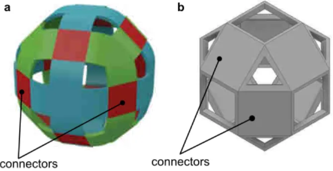
The suggested quasi-spherical catom has a face-centered cubic (FCC) lattice structure as depicted in Figure2a. In this configuration each catom can have up to twelve neighbors catoms. Each neighbor catom can be locked onto the dedicated latching surface, called connector, of the initial catom by the proposed electrostatic actuation. The other surfaces (non-connectors) serve as rolling surfaces during
the displacement. The length of all the surfaces, connectors and non-connectors, are designed such that a catom in movement can always reach another catom latched and connected on the initial catom. Even if this quasi-spherical shape offers several advantages, we propose a modified wuasi-spherical shaper as illustrated in Figure2b. In fact, the latching force that will be obtained from the electrostatic actuation is proportional to the connector surface, hence the quasi-spherical shape of Figure2b will provide better taching strength than that of Figure2a. In the new suggestion, the connectors surfaces for a given volume in order to ensure the required latching force while rolling and passing surfaces (the non-connectors surfaces) based on triangle empty surfaces are still possible. For the rest of the study, a catom of a diameter of 2 cm is considered with connector’s surface of 8 mm×8 mm.
connectors
a b
connectors
Figure 2.Catom’s CAD structure. (a) Quasi-spherical catom shape. (b) Catom maximizing the surface of connectors.
2.2. Principle of Electrostatic Latching
We present here the principle and model of the electrostatic actuation that will be behind the connectors surfaces and that serve first as latching mechanism. The idea is to distribute electrodes on each connector surface. Hence, when applying an electrical potential to the electrodes on one surface of a catom, and when another potential is applied to the electrodes on the surface of the other catom, the potentials difference will create an attraction force between the two surfaces. Thus, a latching of the two catoms is obtained. The advantages of such electrostatic actuation are—(i) suitable for miniaturization, (ii) easy to implement and (iii) can be used for both latching and displacement actuation and l (iv) low energy consumption. This latter advantage is of particular interest since the theoretical energy consumption is zero in steady state and non zero in transient state, which is very fast. In this paper, we investigate only the latching capability of the catoms. The idea consists in assessing the provided force according to the applied voltage and the geometrical features of the electrodes on each connectors surfaces. In particular, we will study and derive the required force to maintain two catoms attached to each others.
Figure3illustrates the principle of the electrostatic actuation where two electrodes surfaces facing each other are electrically charged. Considering this configuration as a parallel capacitor, it is easy to derive the attractive force F between them using the principle of virtual work:
~F= −~∇We, (1)
where Weis the stored electrical energy in the capacitor. In the case of parallel capacitor the following
expression of the force along the vertical axis can be derived.
F= ε0A
2(xins
εr +xair)
2U
2, (2)
where ε0and εr are respectively the dielectric permittivity of the void and the relative permittivity of
the insulation material, A is the area of a connector surface, xinsis the width of the insulation, xairis the
distance of the air gap separating the two plates and U is the voltage or potentials difference between the two electrodes.
electrodes catom 1 catom 2 U 0 x
Figure 3.Principle of electrostatic actuator based on parallel capacitors.
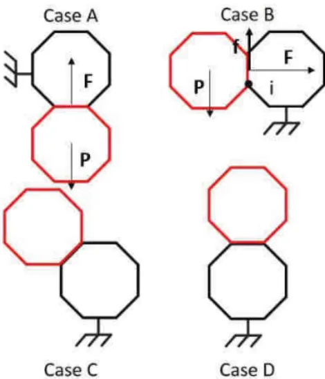
Having the relationship that links the applied voltage U and the electrostatic force F as described in Equation (2), it is easy to derive the required condition to latch two catoms to each other. For this, let us consider the four configurations presented in Figure4. They represent the possible positions between two catoms in latching condition and based on a FCC latice. Among these positions, two are of interest: Case A and Case B. Case A is the critical case where the entire weight of one catom has to be overcame by the connection, whilst case B represents the worst case where the moment to be overcame is maximal. Cases C and D represent less force and less moment than the two first cases, therefore they will not be considered here.
Figure 4.Different possible configurations of catoms based on face-centered cubic (FCC) lattice.
First let us consider case A. The minimum force to maintain the catom is straightforward from the Newton’s first law.
F=mg (3)
where m is the weight of the catom and g is the gravity. By combining Equations (2) and (3), considering that there is an air gap between the two electrodes, the condition in term of voltage that guarantees the latching is obtained: U≥ s 2mgx2 air ε0εrA . (4)
Let us now consider case B. Still using Equations (2) and (3), the required moment around point I (Case B in Figure4) to maintain the catom latched is derived:
Fc
where c is the connector side and r the external radius of the quasi-spherical shape that forms the catom. Combining Equations (2) and (3) leads to the second condition in term of voltage required to make sure that the catom will not roll down when latched:
U≥
s
4rmgx2air
cε0εrA . (6)
From the two conditions in Equations (4) and (6), the final condition to be ensured in order to guarantee both case A and case B, and consequently case C and case D, is:
U=max s 2mgx2 air ε0εrA , s 4rmgx2 air cε0εrA . (7) 2.3. Simulations
To perform the simulations, numerical values for the further realization are used. The material to be used is the VISIJET M3 Crystal material, a plastic used for 3D printing. From this material and using Autodesk Inventor 2019 CAD software, we estimate the weight of the catom to be 500 mg. From this weight and using Equation (3), the force has to be greater than F = 5.10 mN in order to lift a catom in vertical position (case A). To derive the necessary conditions in term of applied voltage and distance between electrodes that can provide this amount of force, we start by simulating the general governing equation of electrostatic actuation as described in Equation (1). To this aim, some hypothesis are made: (i) εris taken equal to 1 as we assume that only air insulates the two electrodes, and (ii) the electrodes
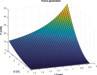
are perfectly planar. The resulting force versus the applied voltage and the gap between electrodes is given in Figure5. 0 5 10 20 4 30 F [mN] 40 3 50 U [V] Force generated 2 0.7 0.8 0.9 1 10-6 x [m] 1 1.1 1.2 1.3 0 1.5 1.4 10-6 x [m][µm]
Figure 5.Force generated versus voltage and distance between two electrodes.
As expected from Equation (2), Figure5clearly reveals that the distance between the electrodes has an important role regarding the generated force: the further distance between two electrodes is, the less generated force will be. In other words, few hundreds of nanometers of additional distance will drastically decrease the generated force. In counterpart, reducing the electrodes gap in order to increase the amount of force for a given voltage has a limitation. Indeed, one has to take into account the dielectric strength (breakdown voltage) of the material isolating the electrodes. When subjected to a voltage higher than its dielectric strength, the material breaks and electrical arcs will appear between the two electrodes and will reduce the generated force to zero. Furthermore when the material is broken, the electrodes can not be used anymore. As an example, let us consider a gap between xair
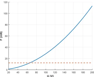
respecting the two previous conditions. Considering as example a voltage of 65.8 V, one can obtain from the intersection of the two curves illustrated in Figure6: the force generated by the weight of the catom and the electrostatic force attracting each other the electrodes separated by a distance of 10 µm. For example, the air has a dielectric strength of 3.0 Mv/m. Hence, a voltage of 30 V can cause breakage of the air between the two electrodes distanced of 10 µm. Thus, another insulation material has to be used or added to separate the electrodes in the suggested electrostatic actuators. In this regard, SiO2(silica) material is of particular interest since it has a dielectric strength of 40 MV/m that
requires 390 V of voltage to reach the breakage [21]. In addition, the integration and deposition of this material to the electrodes is standard using clean room facilities and thus a good flatness of the final electrodes will be ensured. With this SiO2layer on each electrode, the final gap between two electrodes
is: x=xair+xins.
Figure 6.Force generated versus voltage considering a gap of x = 10 µm.
3. Fabrication of the Catoms
As from the previous section, ensuring a fully planar gap between two electrodes is a key challenge for electrostatic actuation. To ensure a high quality planarity, we combined micro-fabrication technique and a high-resolution 3D printing. Micro-fabrication technique was used to fabricate electrodes in order to guarantee a high level of flatness whilst 3D printing was used to print a catom where grooves were expected to host the electrodes.
3.1. Realization of the Catom Structure
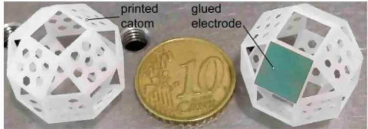
As quasi-spherical shape is not easy to fabricate with conventional process, a 3D printer is used for fast and cheap prototypes it. It consists of a PolyJet SD 3500 printer (3D SYSTEMS company, South Carolina, USA). The printer uses a Visijet M3 Crystal material to print the design itself while wax is used as a support material. The model is constructed by adding material layer by layer. After printing, the model is placed inside an oven to remove the wax material. To reduce the catom weight as much as possible, and to make easy the further electrodes wiring, holes are created within the catom. The resulting structure after printing is presented in Figure7(left). The printed catom presents a weight of m = 373 mg.
Figure 7.Printed catom’s structure and catom with glued electrode. 3.2. Clean Room Process
As pointed in Section2.3, the distance between electrodes has very high impact on the force generated by the catoms. Even a small difference in the gap can drastically reduce the produced force. To overcome this limitation, a high quality of flatness of the electrodes is required. To reach this, clean room technologies are the suitable solution since they can guarantee the required flatness of the surface. It is worth to notice that micro-fabrication process guarantees a very high level of flatness since the deposition process is controlled with a maximum error of 3% over the whole wafer. Reported to the size of one electrode this error becomes smaller at around 0.2%. Based on these technologies, the flow chart process given in Figure8is developed in this work to fabricate the electrodes and the deposition of the additional insulator based on SiO2.
Silicon 10-100 Ohm.m 300 µm
Protective resin S1318
Cr/Au 100 nm
Wiring
a
b
c
d
e
or
200 nm
SiO
2Si
3N
4SiO
2bottom face removal
Figure 8.Flow chart of the clean room process used to fabricate the electrodes.
The process starts by growing an insulation layer of 200 nm of SiO2on both sides of a low resistant
wafer with a thickness of 300 µm using a thermal oxidation oven (see Figure8a). The oxidized layer, also referred to as insulator or insulation layer, has a 1.5% error margin on its thickness. Then, the SiO2
on the bottom face is removed. To do so, the top face is protected with a S1318 resin (see Figure8b) and the wafer soaks in a BHF bath (see Figure8c). Then, the bottom side of the wafer is metallized using a cathode-ray pulverization machine to apply first a 20 nm layer of chrome and then a 80 nm layer of gold (see Figure8d). The metal layer has two main functions: (i) first, it is used to act as soft layer to glue the wire without (or with very few) oxydation, (ii) second, it permits to have a better distribution of the electric field in the silicon layer allowing a more homogeneous distribution of the charge. In the last step, the wafer is cut following a square pattern of 8 mm side, which represents the size of the electrodes. The electrodes are chosen in the middle of the wafer to further minimize the flatness error. Then a silver paste is applied to connect an insulated wire of a diameter of 0.2 mm on the metallized side (see Figure8e). This wire is chosen to be very flexible and light in order to neglect its effects during the experiments. Finally, electrodes and their wires are glued on the catom structure as shown in Figure7(right). SiO2material is privileged as insulator because of its high dielectric strength
and its high dielectric constants. Si3N4can also be used but the quality of its deposition onto the catom
surface is challenging.
To do the assembly and fabricate the final catom, a small amount of superglue is spread out along the catom’s grooves, then the electrodes are glued. This operation is done manually since the size of the electrodes (side of 8 mm) and the structure (diameter of 2 cm) are sufficiently large to be manipulated by manual tweezers. In this case, there is no need to: (i) master the glue, (ii) master applied force or (iii) use an automated assembly technique.
4. Experimental Validation
4.1. Presentation of the Experimental Benchmark
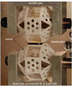
The experimental benchmark used to validate the fabricated catoms is depicted in Figure9. This setup is used to characterize the generated force when two catoms latch each other. The experimental setup is composed of:
- a tensile test machine equipped with a load cell having a force capability up to 2 N with a resolution of 3 mN. The top part of the machine is the moving part which produces a tensile force. The bottom part is fixed and connected to a load cell which acts as the sensor.
- two catoms fixed on the jaws of the tensile machine. One catom is fixed on the top of the machine while the second is fixed on the bottom of the machine.
- a generator that can provide a voltage up to 200 V allowing to supply the electrodes of the catoms. - and a computer and acquisition system used to acquire signals from the tensile machine,
to visualize and to record data, and to analyze them.
Figure 9.Experimental bench.
The experimental setup are placed on an anti-vibration table to limit the influence of mechanical vibration on the load cell of the tensile machine.
4.2. Tests and Results
The latching capability of the catom is tested for different applied voltages. The idea consists to do a characterization of the interaction force between two catoms according to the applied voltage.
In other words, it aims to derive a relationship between the applied voltage and generated force. For each test, the same experimental protocol given below is followed:
1- The first catom is clamped to the bottom jaw of the tensile machine. 2- The second catom is placed on top of the first one.
3- The two catoms are powered to latch them together.
4- The second catom is clamped to the top jaw of the tensile machine while latching to the first catom. 5- The tensile test begins by moving up the top jaw of the tensile machine with a constant speed
of 1 µm/s.
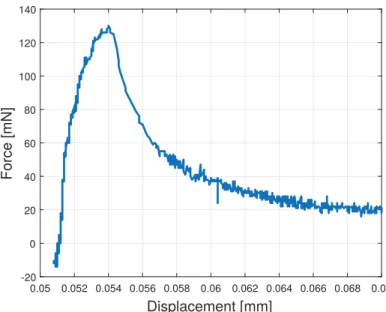
The experiments were carried out using several sets of catoms and at different voltages. Since the test is not destructive, we were able to take several measurements for each voltage values and each catom sets. Figure10shows a typical interaction force recorded by the load cell of the tensile machine. Two distinct phases can be observed. At the beginning, the force grows quickly until the breakout force is reached. Then instead of dropping to zero instantly, the force decreases slowly. This is the effect of electrostatic force which decreases when the distance between two electrodes increases.
0.05 0.052 0.054 0.056 0.058 0.06 0.062 0.064 0.066 0.068 0.07 Displacement [mm] -20 0 20 40 60 80 100 120 140 Force [mN]
Figure 10.Breakout Force measured during the tensile test at 170 V.
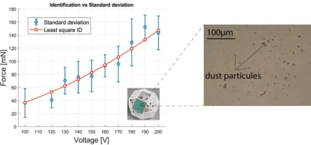
Here, only the peak is of interest because we are only studying the latching mechanism. The measurement is repeated 150 times for different voltages between 100 V and 200 V. The minimum voltage is 100 V because below this point, the measurement noise becomes important compared to the produced force of the mechanism. Each test gave off a force value depending on the applied voltage and the results are compiled in Figure11. This curve particularly shows the standard deviation of the measured force per voltage and the least square identification used to verify the model given in Equation (2). The red curve is the same as the curve given in Figure6where the air gap value is adapted to fit the model. These results are discussed in the next subsection.
Figure 11.Standard deviation curve versus least square identification method. 4.3. Discussions
When comparing the experimental values with the theory for a gap of 600 nm (equals to the sum of the SiO2thicknesses of the two antagonist electrodes), a huge difference is observed. The theory exhibits
60 mN of force for 100 V of voltage while the experiment gives a generated force of approximately 40 mN. To analyze the difference, let us go back to Equation (2). Thanks to the clean room process of fabrication, parameters xinsand A have very negligible errors compared to the theory. Hence the
remaining parameter is xairwhich is the air gap. This air gap can come from two different factors:
(i) a tilt or parallelism error between the electrodes, (ii) dust particles. Regarding the slight tilt, it come from the gluing or the position of a catom according to another one, but the generated force can compensate it since the electrodes are planar and one catom is always free. However dust that comes from the environment cannot be compensated because it introduces a physical gap that increases the distance between two electrodes and as a consequence decreases the generated force. To support this hypothesis a zoom of an electrode is shown in Figure11where dust particles can be seen. Assuming such dust, using a parametric identification technique, we found that an air gap of about 12 µm potentially exists between the two electrodes.
Because dust size is approximately 11 µm, this assumption well fits to the experimental results in Figure11. Regarding the high standard deviation in this curve however, its cause is due to the difficulty to set the same initial condition each time we start a new test. When the two catoms split, they slightly move due to the used ‘pin-jaws’. In addition, the pin-jaws have a certain flexibility which allows to easily re-latch the catoms between each test, and thus implies that the catoms are not in the exact same position than before. Moreover, in the meantime, it is also possible that additional dust come to or disappear from between the two electrodes and consequently change the air gap previously mentioned. Finally the electrodes are also fragile: when subjected to shocks they can stop working due to the dielectric layer breaking and the prolonged usage with repeated latching and unlatching can wear off the electrodes.
In spite of these difficulties, the identified relation between the applied voltage and the generated force is important since it allows to predict the sufficient amount of force to achieve a given configuration. Keeping in mind this relation, we performed different configurations. The results shown in Figure12are very promising in terms of latching capabilities of a catom. Indeed Figure12a,b show that one can achieve the conditions given in Section2.2. On the other hand Figure12c,d reveal that when a maximum voltage of 200 V is applied, the catom’s latching capabilities are strengthen. Such high voltage contributes for the stability of the latching for overhanging situation or when a heavy object (75 times heavier than one catom) have to be supported by the catom.
Figure 12.Experimental validation of different catom’s configurations. (a) Catom latching in overhang configuration (Case B). (b) Catom latching in vertical configuration (Case A). (c) Catom latching in overhang configuration while lifting a heavy weight. (d) Two catoms latching following Case C.
5. Conclusions
This paper presented the design of a new module for programmable matter. Called catom, the module was typified by a quasi-spherical shape with face-centered cubic lattice and had centimeter scale. Electrostatic actuation was studied for the latching capability of the catom. After describing the catom’s geometry, we provided the latching conditions considering low energy, miniaturization and sufficient force constrains. The fabrication of the catoms was afterwards presented and simulation and experiments were carried out. The results demonstrated that the latching was strong enough under various conditions.
Future works consist in improving the robustness of the electrodes regarding their wearing off by adding a protecting layer and/or utilizing a metallic wafer. Future works also include the study of flexible electrodes for a better fitting with the quasi-spherical shape. On the other hand, the used electrostatic actuation will also be studied and extended such that one catom can move relative to another catom instead of only working in latching mode. In this future work, additional parameters such as the friction and the catom inertia will have to be considered in order to find the conditions of rolling/toplling of a catom relative to another one. Finally, perspective works will also include the integration of a super capacitor or a non-contact source to supply each catom.
Author Contributions: Authors contributions: R.C. did the investigation and A.M.-O., M.R. and P.L. are the supervisers of the works. All authors have read and agreed to the published version of the manuscript.
Funding: This work is supported by the French “Investissements d’Avenir” program, ISITE-BFC project (ANR-15-IDEX-03) and the EIPHI Graduate School (contract “ANR-17-EURE-0002”). This work is also partly supported by the french RENATECH network and its FEMTO-ST technological facility.
Acknowledgments: The authors would like to express their thanks to the french “Investissements d’Avenir” program and the EIPHI-UBFC Graduate school program. We would like also to thank Dr. Xavier GABRION for helping us with the experimental characterization.
Conflicts of Interest:The authors declare no conflict of interest.
References
1. Toffoli, T.; Margolus, N. Programmable matter: Concepts and realization. Phys. D 1991, 47, 263–272. [CrossRef]
2. Yim, M.; White, P.; Park, M.; Sastra, J. Modular Self-Reconfigurable Robots. In Encyclopedia of Complexity and
3. Fukuda, T.; Ueyama, T.; Kawauchi, Y.; Arai, F. Concept of cellular robotic system (CEBOT) and basic strategies for its realization. Comput. Electr. Eng. 1992, 18, 11–39. [CrossRef]
4. Satoshi, M.; Eiichi, Y.; Kohji, T.; Kurokawa, H.; Kammimura, A.; Kokaji, S. Hardware Design of Modular Robotic
System; IEEE IROS: Piscataway, NJ, USA, 2000.
5. Romanishin, J.W.; Gilpin, K.; Rus, D. M-Blocks: Momentum-Driven Magnetic Modular Robots. In Proceedings of the IEEE/RSJ International Conference on Intelligent Robots and Systems, Tokyo, Japan, 3–7 November 2013; pp. 4288–4295.
6. Available online:http://www.cs.cmu.edu/~claytronics/hardware/helium.html(accessed on 3 June 2020). 7. Garcia, R.F.M.; Hiller, J.D.; Lipson, H. A Vacuum-Based Bonding Mechanism for Modular Robotics; IEEE ICRA
Workshop: Piscataway, NJ, USA, 2010.
8. Kotay, K.; Rus, D.; Vona, M.; McGray, C. The Self-Reconfiguring Robotic Molecule; IEEE: Piscataway, NJ, USA, 1998. 9. Murata, S.; Kurokawa, H.; Yoshida, E.; Tomita, K.; Kokaji, S. A 3-D Self-Reconfigurable Structure; IEEE ICRA:
Leuven, Belgium, 1998; pp. 432–439.
10. Jorgensen, M.W.; Ostergaard, E.H.; Lund, H.H. Modular ATRON: Modules for a Self-Reconfigurable Robot; IEEE IROS: Piscataway, NJ, USA, 2004; Volume 2, pp. 2068–2073.
11. Chirikjian, G. Kinematics of a Metamorphic Robotic System; IEEE ICRA: Leuven, Belgium, 1994; pp. 449–455. 12. Will, P.; Castano, A.; Shen, W. Robot modularity for self-reconfiguration. Proc. SPIE 1999, 3839, 236–245.
[CrossRef]
13. Belisle, R.; Yu, C.; Nagpal, R. Mechanical design and locomotion of modular-expanding robots. In Proceedings of the IEEE 2010 International Conference on Roboticsand Automation Workshop, Modular Robotics: State of the Art, New York, NY, USA, 3 May 2010; pp. 17–23.
14. Karagozler, M.E. Design, Fabrication and Characterization of an Autonomous, Sub-Millimeter Scale Modular Robot. Ph.D. Thesis, CMU, Pittsburgh, PA, USA, 2012.
15. Gilpin, K.; Knaian, A.; Rus, D. Robot Pebbles: One Centimeter Modules for Programmable Matter through
Selfdisassembly; IEEE ICRA: Leuven, Belgium, 2010; pp. 2485–2492.
16. Piranda, B.; Laurent, G.; Bourgeois, J.; Clévy, C.; Mobes, S.; Le Fort-Piat, N. A new concept of planar self-reconfigurable modular robot for conveying microparts. Mechatronics 2016, 23, 906–915. [CrossRef] 17. Ostergaard, E.H.; Kassow, K.; Beck, R.; Lund, H.H. Design of the ATRON lattice-based self-reconfigurable
robot. Auton. Robot. 2006, 21, 165–183. [CrossRef]
18. Pengwang, T.E.; Rabenorosoa, K.; Rakotondrabe, M.; Andreff, N. Scanning micromirror platform based on MEMStechnology for medical applications. Micromachines 2016, 7, 24. [CrossRef] [PubMed]
19. Available online:https://projects.femto-st.fr/programmable-matter/teams(accessed on 3 June 2020). 20. Piranda, B.; Bourgeois, J. Designing a quasi-spherical module for a huge modular robot to create
programmable matter. Auton. Robot. 2018, 42, 1619–1633. [CrossRef]
21. Available online:http://eesemi.com/sio2si3n4.htm(accessed on 3 June 2020).
© 2020 by the authors. Licensee MDPI, Basel, Switzerland. This article is an open access article distributed under the terms and conditions of the Creative Commons Attribution (CC BY) license (http://creativecommons.org/licenses/by/4.0/).