This is an author-deposited version published in:
http://oatao.univ-toulouse.fr/
Eprints ID: 15117
To cite this version:
Cailhol, Simon and Fillatreau, Philippe and Zhao, Yingshen and Fourquet,
Jean-Yves Hierarchic interactive path planning in virtual reality. (2015)
In: Informatics in Control, Automation and Robotics. (Lecture Notes in
Electrical Engineering). Springer, pp. 179-203. ISSN
1876-1100
O
pen
A
rchive
T
oulouse
A
rchive
O
uverte (
OATAO
)
OATAO is an open access repository that collects the work of Toulouse researchers and
makes it freely available over the web where possible.
Any correspondence concerning this service should be sent to the repository
administrator:
[email protected]
Hierarchic interactive path planning in Virtual Reality
Simon Cailhol, Philippe Fillatreau, Yingshen Zhao and Jean-Yves Fourquet
Laboratoire G´enie de Production, INP-ENIT, 47 Av d’Azereix, 65000 Tarbes, France {simon.cailhol, philippe.fillatreau, yingshen.zhao,
jean-yves.fourquet}@enit.fr
Keywords: Interactive path planning, control sharing, virtual reality, manipulation tasks
Abstract. To save time and money while designing new products, industry needs tools to design, test and validate the product using virtual prototypes. These vir-tual prototypes must enable to test the product at all Product Life-cycle Man-agement (PLM) stages. Many operations in PLM involve human manipulation of product components in cluttered environment (product assembly, disassembly or maintenance). Virtual Reality (VR) enables real operators to perform these tests with virtual prototypes. This work introduces a novel path planning architecture allowing collaboration between a VR user and an automatic path planning system . It is based on an original environment model including semantic, topological and geometric information, and an automatic path planning process split in two phases: coarse (semantic and topological information) and fine (semantic and ge-ometric information) planning. The collaboration between VR user and automatic path planner is made of 3 main aspects. First, the VR user is guided along a pre-computed path through a haptic device whereas he VR user can go away from the proposed path to explore possible better ways. Second the authority of automatic planning system is balanced to let the user free to explore alternatives (geomet-ric layer). Third the intents of VR user are predicted (on topological layer) to be integrated in the re-planning process. Experiments are provided to illustrate the multi-layer representation of the environment, the path planning process, the control sharing and the intent prediction.
1
Introduction
The industrial product development process is going faster and faster with more and more complex products. This leads to a need for tools allowing to rapidly test a product at all the Product Lifecycle Management (PLM) stages during the design phase. There is a particular need for the tasks that involve human operator manipulation. Here comes the interest of Virtual Reality (VR) to run these tests with virtual prototypes instead of expensive and time consuming real ones [9]. The main issue of tasks such as the ones involved in assembly, dismantling and maintenance is to find paths for the systems components and parts.
In this context, we propose a collaborative path-finding system based on the in-teraction of a user immersed in a VR simulation and an automatic path planning process inspired from robotics.
Collaboration is defined as follows. The system provides a initial planned path and the user is guided along this computed trajectory through an haptic device.
However, the user can disagree with the proposed path and can try to go in another direction. Then the system computes a new path every time the user tries to test another solution. Thus, it is able to take into account the user’s interactions in real-time to update the suggested path and it involves control sharing between the user and the planner while performing the task.
While robotics path planners mainly deal with geometric aspects of the environ-ment, the human user immersed in VR application handles more abstract concepts built from his experience. Thus, we chose to provide our automatic path planner with semantic and topological information in addition to the traditional geomet-rical ones. According to this heterogeneous information, we split the planning process in two phases: a coarse planning dealing with topological and semantic models of the environment (the places, their semantics and their connectivity) and a fine planning dealing with geometry and semantics (geometry of obstacles, geometry of places and their complexity). This planning process partitioning pro-vides a framework compatible with the human path planning process described in [3].
Thus, the originality of the proposed interactive path planner consists in using the information of a multi-layer environment representation (semantic, topological and geometric) for path planning, but also for control sharing. All these environ-ment models are used by distinct planner layers to perform the coarse (semantic and topological aspects) and fine (semantic and geometric aspects) planning and to assist VR user. The actions of the VR user are also taken into account in real-time to update the proposed path.
This paper first gives, in section 2, an overview of the state of the art of the different fields involved (automatic path planning, control sharing, interactive path planning). The architecture of our novel multi-layer environment model and multi-layer interactive planner is presented in section 3. The implementation of this architecture on our VR platform is described in section 4. Proof of concepts experiments are presented in section 5. These experiments show that our novel multi-layer architecture finds more relevant paths with faster processing times than the purely geometrical approaches from the state of the art. Thus our orig-inal approach allows a better real-time interactive planning. Forig-inally, section 6 summarizes the contribution of this paper and introduces the future steps of this work to handle real industrial manipulation tasks.
2
State of the art
2.1 Automatic path planning
The automatic path planning issue has been deeply studied in robotics. The re-lated works are strongly based on the Configuration Space (C) model proposed by [15]. This model aims at describing the environment from a robot’s Degrees of Freedom (DoF) point of view. The robot is described using a vector where each dimension represents one of his DoF. A value of this vector is called a configura-tion. So, all the possible values of this vector form C. This C can be split into free space (Cf ree) and colliding space (Cobs) where the robot collides with obstacles of the environment. With this model, the path planning from a start point to a goal point consists in finding a trajectory in the Cf reebetween these two points in the CS.
The main strategies for path planning are given in Table 1 where we distinguish the ones using deterministic methods from the ones using probabilistic methods, but also, the ones involving a global approach from the ones involving a local one. More details on path planning algorithms and techniques are available in [12].
Global approaches Local approaches Deterministic
strategies
Cells decomposition
Roadmap Potential fields
Probabilistic
strategies PRM RRT and RDT
Table 1. The main path planning approaches
2.2 Control sharing
Existing applications involving path planning with human interactions (robot tele-operation, semi-autonomous vehicles, virtual environment exploration,...) al-low us to identify two aspects in control sharing:
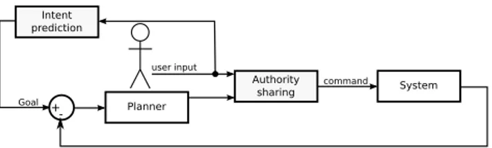
– Authority sharing: it aims at defining how the authority on the system is shared between automatic planner and human. To deal with this issue, dif-ferent strategies can be found in the literature. The use of virtual fixtures [16], the allocation of the authority to the automatic system for fine motion operations [2], the progressive transfer of authority to robot for fine motion while reaching the goal [18], for an anthropomorphic robot, the control of Cartesian position and orientation of end effector by user and joint control by planner [19]. The authority sharing through haptic devices were studied for semi-autonomous vehicles driving. In this case, inspired from the horse riding experience, [10] suggests to use an haptic interface with a H-mode to perceive user’s involvement and allocate the authority according to it (the higher the user involvement is, the more authority he has).
– Intent prediction: it aims at predicting the intent of the human to define the goal of an automatic controller and thus to assist the human performing the task. These techniques are strongly based on behavior or trajectory recogni-tion [1, 8, 13, 20], on minimum jerk criterion [18], on model predictive con-trol [4, 14]. Dragan also recently proposed to find the targeted goal among a set of potential ones from the current movement direction [7].
We summarize these two control sharing aspects in Fig. 1 where the yellow boxes illustrate the control sharing.
These techniques allow involving human and automatic planning system to per-form a task. However, the user’s actions do not affect the automatic planner strat-egy to compute the path.
2.3 Interactive path planning
Some works propose collaboration between a human operator and an automatic planner in the path planning process. The simpler one [11] uses a potential field strategy. An attractive field to the goal is computed and used to guide the user
Fig. 1. Sharing control model in semi-automated planning
through a haptic device. This potential field does not consider obstacles, thus, it is up to the user to handle the obstacle avoidance. Another interactive planner from [11] guides the user along a computed trajectory. To compute this trajectory in real-time, a cell decomposition of the free space is used to define a 3D tunnel (a continuous set of geometrical cells between start an goal configurations). Then a RDT algorithm computes a path within the 3D tunnel. The whole trajectory computation process is performed again if user goes away from the proposed trajectory. Finally, an interactive planner built from a probabilistic strategy [17], uses the users action to constraint the random sampling of the configuration space in the RRT growing.
These three planners do not involve the human user in the same way. The first one gives a strong responsibility to the user (it is up to him to deal with the obstacles and to avoid collisions). The second one suggests a whole trajectory the user can go away from to restart the whole planning process. The last one allows the user to point a direction that gives to the planner a preferred direction to explore.
3
Proposed interactive planner
This section presents the concepts of the strategy used in the interactive planner shown in Fig. 2 where colors are linked to the environment and planning layers: yellow for geometry, orange for topology and red for semantics. The same colors are used in the algorithms to specify the involved layer. The concepts used are illustrated here with 2D illustrations for clarity, but the model stands identical for 3D simulations.
We argue that involving semantic and topological aspects in path planning in addition to the common geometric ones allows adapting the planning strategy to the local complexity of the environment. To deal with it, a coarse planning is performed first using mainly semantic and topological information. Then, heavy geometric path planning strategies are used merely locally (according to the place complexity). This allows us to plan path without disturbing user’s immersion in the VR simulation, and to take into account user’s action while performing the task to interactively update the planned path.
The contribution of the work presented here is thus two-fold:
– Guidance is provided in real-time to the user by improving the path plan-ning processing times using the semantic and topological information of the environment.
– User’s actions are integrated in real-time in the planning process and used to update the planned path, and so, the guidance submitted to the user.
Environment representation InteractivePlanner 1..* 1..* 1 2 1 1..* 1..* 0..* 1 1..* Asks ◮Asks Determines◮ "Asks Monitors◮ "Transmit probabilities Environment obstacles Obstacle
Geometric cell
Intersects
Free space
Area Place
Border Topological graph
Semantic planner
Topological planner
Semantic interpreter
Topological path Topological step Geometric planner Local planner
Activates◮ Covers Authority controller ◮Uses Torsor "Produces Trajectory Step trajectory Intent predictor ◮Checks Explores Deals with
Fig. 2. UML Domain model of environment representation and interactive planner
3.1 Environment representation
The topological information of the environment is represented as a set of Places (P1to P7 in Fig. 3.a) and transition areas between these Places, which we call Borders; Bi,jdenotes the transition area between places Piand Pj. The topolog-ical layer of our environment model is made of a Topologtopolog-ical graph (Fig. 3.c) connecting places and borders. In this Topological graph, the nodes correspond to the Borders, and the edges to the Places. Figure 4.a shows the distance between the borders’ centers in place P4. These distances are attributes set to the edges of the topological graph (Fig. 4.b for place P4).
The semantic information is attached to places. Semantic attributes are assigned to the places to describe their complexity (size, shape, cluttering,...) for path plan-ning.
The geometric environment representation consists in a geometric description of the environment’s objects and a cell decomposition of the Free space. The Objects are described with meshes; the Free space is described with a quadtree (an octree in 3D) decomposition (Fig. 3.d).
This multi-layer environment model is built as given in algorithm 1. First (line 2), the 3D mesh of environment Objects are loaded. Second (line 3), the Free space decomposition is computed. Third (line 4), the free space decomposition is used to identify the Places. Fourth (line 5), the Places found are used to define the Borders. Then (line 6), the Borders are connected building the Topological graph. Last (line 7), semantic attributes are set to the Places.
3.2 Planning aspects
According to these environment models, the planning process is split in two stages: the coarse planning involving semantic and topological layers and the fine planning involving semantic and geometric layers
O1 O2 O3 O4 not comple x not comple x complex complex very complex very complex v ery comple x comple x cluttered not complex fix ed fix ed fixed mo ving
a.2D environment b.Semantic model
B1,5 B2,7 B1,6 B2,8 B3,5 B3,7 B4,6 B4,8 B3,9 B3,10 B4,9 B4,10 P1 P2 P3 P4 P5 P7 P8 P6 P9 P10 P3 P3 P3 P3 P4 P4 P4 P4
c.Topological graph d.Free space decomposition Fig. 3. Different perceptions of environment for user and planner
× × × × d1 d2 d3 d4 d5 d6 a.Place distances. B4,6 B4,8 B4,9 B4,10 d1 P8 P6 d2 d3 d4 d6 d5
b.Place topological graph.
a.Place P4distances b.Place P4topological graph Fig. 4. Topological graph building for place P4
Algorithm 1: build environment model
1 begin
2 load Objects 3D Meshes ;
3 build Free space decomposition ;
4 build Places ;
5 build Borders ;
6 build Topological graph ;
7 assign attributes to Places ;
Coarse planning To adapt the geometric planning strategy to local complexity,
the whole path is split in steps. A step refers to a place of environment represen-tation. A step also refers to a border to reach to fulfill the step. The geometric planning strategy is thus chosen according to the semantic information of step’s place.
Algorithm 2: coarse planning
1 begin
2 update Topological graph (start & goal) nodes ;
3 update Topological graph’s costs ;
4 explore Topological graph ;
5 build Topological path and Topological steps ;
6 for Topological step∈ Topological path do
7 define milestone for Topological step ;
Algorithm 2 describes this stage. Two nodes corresponding to start (S) and goal (G) configurations are added to the topological graph (line 2). To direct the graph exploration the Semantic planner, based on the Semantic interpreter, assigns costs (C) to graph’s nodes (ni,j) and edges (ek) (line 3). These costs are chosen accordingly to the semantic information of involved places (see (1)).
Cni,j= f (sem(Pi),sem(Pj))
Cek= f (dk,sem(P(ek)))
(1) Where sem(P) is the semantic information of place P, dkis the distance attribute of topological graph’s edge ekand P(ek) its place attribute; ni,jis the node linked to the border Bi,jbetween Piand Pj.
These costs make the cost of a path (Cpath) computation possible (2). Cpath=
∑
ni,j∈path
Cni,j+
∑
ek∈path
Cek (2)
Then the Topological planner explores the graph (line 4) thanks to a Dijkstra al-gorithm [6] to find the less expensive Topological path between start and goal
nodes. This Topological path is used to split the trajectory in Topological steps (line 5), each step corresponding to a place to cross (a edge of Topological path) and a Border to reach (a node of topological path). Figure 5.a shows the Topolog-ical pathfound in the environment of Fig. 3.a. Figure 5.b focus on the edge and the node corresponding to the second step of this path.
S G B1,5 B2,7 B1,6 B2,8 B3,5 B3,7 B4,6 B4,8 B3,9 B3,10 B4,9 B4,10 P1 P1 P1 P2 P3 P4 P5 P7 P8 P6 P9 P10 P3 P3 P3 P3 P4 P4 P4 P4 P2 P2
,5
P
5
B
3,5
P
3
a.Topological path found b.Second topological step Fig. 5. Steps of a topological path
Fine planningThis planning stage consists in finding the concrete geometrical
path. To do so, each Topological step is used to define a milestone configuration within the border to reach (line 6-7). Then, accordingly to the semantic informa-tion of the place to cross, we adapt the geometric path planning strategy. Indeed, the aim of our architecture is to be able to choose the best geometric planning method among a set of available ones for each step. For now, we use two geomet-ric planning strategies. These two strategies deal with the two distinct geometgeomet-ric environment models (Obstacles and Free space description). Depending on the semantic attribute describing the place’s cluttering by mobile obstacles, the ge-ometric planner can perform a RRT algorithm (when the place is cluttered) on the part of the octree corresponding to the step’s place to set intermediate mile-stones within the step. When all the milemile-stones have been defined, the Local plannerguides the user toward the next milestone. It computes a linear interpo-lation between current configuration and milestone’s configuration, and uses this interpolation to apply a Torsor on the haptic device.
Coarse and fine planning organization The coarse and fine planning are
used to manage the whole planning. The Topological path and its steps are con-cepts allowing the planning layers sharing the necessary information. When the Topological pathis found and the Topological steps are defined, the steps infor-mation is used by the Semantic planner to set the geometric layer accurately.
3.3 Process monitoring
Algorithm 3 shows how the planning layers are involved to monitor the plan-ning process. While the user is performing the task, he is guided toward the next
milestone configuration through the haptic device. This next milestone is updated while the user moves along the path. On the geometric layer, the next milestone is set to the Local planner for the guidance computation when the current one is considered as reached (line 11-12). The goal is considered as reached when the distance between the goal and the current position is smaller than θd. On the topological layer, the milestone is a Border, so even if the user is guided toward a geometric configuration set within the Border, the milestone is considered as reached as soon as the user enters the Border. When the target Border is reached (line 2), the next Topological step is used to set the Local planner for the guidance computation (line 7-9), except if the current step was the last one. In this case, the last milestone must be reached to consider the task as achieved (line 3-5).
Algorithm 3: process monitoring
1 begin
2 if Topological step= achieved then
3 if current step= last step then
4 if Milestone reached then
5 achieved= true;
6 else
7 set next Topological step in Local planner ;
8 if Topological step’s Place cluttered then
9 run RRT on Topological step ;
10 else
11 if Milestone reached then
12 set next milestone to Local planner ;
3.4 Control sharing aspects
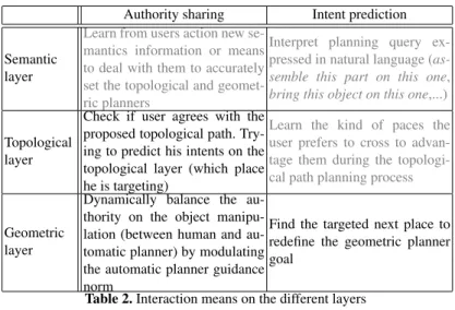
The planner provides user with a guidance torsor through the haptic device used for object manipulation. This Local planner computes the guidance torsor. For each layer of such a planner architecture, specific ways to share control can be proposed as shown in Table 2.
In Table 2 it appears that the intent prediction for the geometric layer is directly linked to the authority sharing of the topological layer. Indeed, within a Place, the set of potential goals to get out of this Place is made of the corresponding Borders. The intent prediction is made with geometric movement and geometric information on Borders. The re-planning is made by the Topological planner for a new Topological path definition.
The same logic applies for the intent prediction of the topological layer and the authority sharing of the semantic layer. Cost functions of (1) may be learned from the places the user prefers to cross. Indeed the preferred places attributes can be identified from all the re-planning done due to users action. The new cost values defined with these functions will thus change all the incoming topological path re-planning.
Authority sharing Intent prediction
Semantic layer
Learn from users action new se-mantics information or means to deal with them to accurately set the topological and geomet-ric planners
Interpret planning query ex-pressed in natural language (as-semble this part on this one, bring this object on this one,...)
Topological layer
Check if user agrees with the proposed topological path. Try-ing to predict his intents on the topological layer (which place he is targeting)
Learn the kind of paces the user prefers to cross to advan-tage them during the topologi-cal path planning process
Geometric layer
Dynamically balance the au-thority on the object manipu-lation (between human and au-tomatic planner) by modulating the automatic planner guidance norm
Find the targeted next place to redefine the geometric planner goal
Table 2. Interaction means on the different layers
The control sharing of the proposed planning architecture is focused on the geo-metric and topological layers. We implemented A H-mode from [10] for geomet-ric authority control. We also developed an intent prediction inspired from [7] to make the topological path re-planning available.
Authority sharing To share authority, we chose to use a strategy inspired from
H-modeintroduced in [10]. This strategy aims at modulating the guidance torsor
Gnorm according to the user’s involvement as shown in equation 3.
Guser= modg.G (3)
Where modgis a measure of user’s involvement from modgmin(not involved) to
1 (strongly involved). The lower limit modgmin is chosen to keep the user aware
of automatic planner state as suggested by [16]. In our application of H-mode, we chose to compute modgi on each process loop i from the scalar product of
instantaneous guidance force(−→gi) by the instantaneous movement direction (−→mi) as shown in equation 4. modgi= 1− modgmin 2 − →g i. − → mi k−→gikk−→mik + 1 ! + modgmin (4)
The coefficient obtained with 4 is filtered to obtain a smooth transfer of the au-thority with gf modicomputation given in equation 5.
modgfi = αmodg.modgfi−1+ (1 − αmodg)modgi (5)
Where αmodgis chosen from 0 to 1 accordingly to the loop rate and the transfer
time needed. The gf modicoefficient obtained is applied to equation 3 to have our
effective authority control given in equation 6.
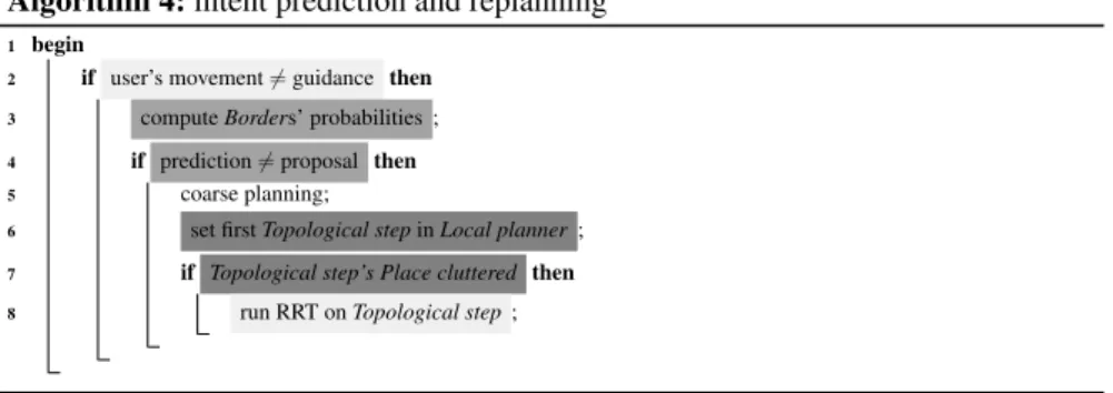
Intent prediction Algorithm 4 shows the process used to define if a coarse re-planning is necessary or not. On line 2, if the user is not following the guidance (angle between guidance direction and movement direction greater than threshold angle and movement amplitude greater than a given threshold), it means the user does not agree with the proposed path. He may have found another one or at least needs a new proposal.
To deal with it, the intent prediction we use allows us to define, in a step, for each border of the current Place, the probability that the user is targeting it (line 3). These probabilities are used to define if the user is targeting another border than the one defined in his current step (line 4). In this case a new topological path is defined taking into account user’s will.
Algorithm 4: intent prediction and replanning
1 begin
2 if user’s movement6= guidance then
3 compute Borders’ probabilities ;
4 if prediction6= proposal then
5 coarse planning;
6 set first Topological step in Local planner ;
7 if Topological step’s Place cluttered then
8 run RRT on Topological step ;
To manage it, we decided to adapt Dragan’s strategy [7] using the set of border of the current step’s place as the set of potential goals. Indeed, to predict user’s intent, Dragan computes probabilities for all potential goals by comparing the movement performed and the goal direction. We chose to use a scalar product to compare the instantaneous movement and the goal direction. However, in our simulations, the potential goals (the borders) are not punctual. Thus the point chosen to compute the scalar product must be carefully chosen. Indeed, as shown in Fig. 6, if the centers Ci of borders Biare taken as representative points, the probability to target borders B1and B2will be the same. However, it seems that B2 is more suited to the user. To deal with this issue, we chose to select the borders’ nearest points Niof the movement axis.
B1 B2 − →mi × × × C1 C2 Si × × N1 N2
With such elements, the probability that the border Bj,kis targeted is given in (7) where a scalar product is scaled to fit between 0 and 1.
P(Bj,k) = 1 2 − → mi. −−−→ SiNj,ki k−→mikk −−−→ SiNj,kik + 0.5 (7)
where Siis the instantaneous position on sample i.
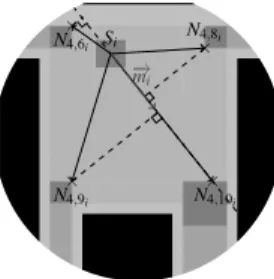
Figure 7 is an example of the points chosen for intent prediction in place P4where Siis the instantaneous position on sample i, −→miits movement direction, and Nj,ki
the point chosen to consider border Bj,k. In this example, the borders classified from the higher to the lower probability to be targeted are: B4,10, B4,9, B4,8and B4,6. × Si N4,6i N4,9 i N4,8i N4,10 i × × × × − → mi
Fig. 7. Border probability computation elements
When the probability of all the borders have been computed, a new topological path computation is performed, according to the condition (8):
max(P(Bi,j))–P(Bstep) ≥ θreplanning (8) where P(Bstep) is the probability computed for the border chosen as the goal of the current step and θreplanning is the threshold used to decide if a topological re-planning is needed or not.
Coarse re-planning When a coarse re-planning is necessary (line 5 of
Al-gorithm 4) the start node of the topological graph is updated to match with the current object position. The borders’ costs are also updated to add costs Cnk,li
corresponding to the intent prediction (see (2)). These new costs direct the next topological graph exploration toward the user’s targeted border. The new topo-logical path computation is done adding new costs Cnk,lito the nodes linked to the
borders. The costs added are chosen accordingly to the corresponding borders as given in (2): Cnk,li= k max(P(Bi,j))–P(Bk,l) max(P(Bi,j)) if Bk,l6= Bstep Cnk,li= Chif Bk,l= Bstep (9)
where k is a multiplicative coefficient and Cha specific cost used to avoid the border of the previous Topological path when computing a new one.
These new costs, being heavy on the previously chosen border, and light on the high probably targeted ones will tend to explore paths through user’s targeted borders and thus define a topological path crossing one of these borders.
3.5 Interactive path planning simulation
Algorithm 5 summarizes the operations made for the interactive path planning. First, an initialization process including environment building and first coarse planning is processed (line 2-7). Then, the proper interactive planning is done in a loop (line 9-14). This loop includes the performed trajectory recording (line 9), the user’s intent prediction and the re-planning to fit with his intent (line 11), the process monitoring (line 12) and the guidance modulation and update (line 13-14).
Algorithm 5: Interactive planning simulation
1 begin
2 build environment model;
3 coarse planning;
4 achieved= f alse;
5 set first Topological step in Local planner ;
6 if Topological step’s Place cluttered then
7 run RRT on Topological step ;
8 while achieved= f alse do
9 record sample configuration ;
10 compute user’s movement direction ;
11 intent prediction and replanning;
12 process monitoring;
13 update authority ;
14 update guidance ;
4
Implementation
We implemented our proposed path planning and environment modeling archi-tecture in VirtoolsTM4.1 software through libraries developed in C++ language. We developed 3 distinct libraries: 2 autonomous libraries corresponding to envi-ronment modeland path planner and an interface library.
4.1 Environment representation built
The environment model is implemented in a dedicated library interfaced to VirtoolsTMwith a specific library.
– The objects of the environment represented through meshes and positioning frames. To build this part of environment model, we use the CGAL project [5]. Semantic attributes are attached to the objects. One of them describes if the object is fixed or not to be able to exclude the moving ones while identifying the places (static mapping of the environment).
– The free space description through an octree decomposition of the 3D scene (in this case also, the nodes colliding with fixed objects are distinguished from those colliding with only moving objects)
– The topological graph to model the places connectivity (the graph’s nodes are the borders, and the edges the places)
– The set of places and their borders. We defined some procedures to automati-cally identify the places from the octree structure. The semantic attributes are characters strings. Their attachment to the places is manually made, choosing for each place the right attributes among a set of available ones. One attribute is automatically set: ”cluttered” if the place contains moving obstacles The attributes available in our simulations allow describing the level of complex-ity of a place as ”low”, ”average”, ”high”, and ”very high”. Another attribute is used to define if a place is ”cluttered”. Finally, ”square”, ”triangular”, ”round” and ”pentagonal” attribute can be set to describe place’s shape.
4.2 Planner implementation
The planner is also implemented in a dedicated library and interfaced to VirtoolsTMusing the same interface library used to interface the environment.
Planning classesFour classes had been defined corresponding to the four
plan-ners. Each of these planner classes deals with an environment model. The local planner provides the user with the guidance. The geometric planner finds, if nec-essary, a geometrical path to cross the clutters Places. The topological planner explores the topological graph to build the path and the steps managed by the lo-cal and the geometric planner. The semantic planner coordinates the whole plan-ning process, asking the topological planner for the topological path and planplan-ning which strategy will be used on the geometric layer.
For the weights computation, we defined the function of (1) assigning the weights as given in (10). Cni,j= Ccomplexity 2 Cek= dk.Ccomplexity (10)
Where Ccomplexitysums two costs:
– the first one is set according to the complexity semantic information of the involved places 0, 0.5, 1 and 5 for low, average, high and very high complex-ity.
– the second one is set according to the shape attribute: 0 if empty, 0.5 if the shape match with the handled object’s shape, and 5 if not.
Control sharing classes Two main classes improve the planner for the control sharing. The first one is related to the Authority Controller. It aims at modulating the guidance norm according to the user’s involvement. It allows user to feel free when he is exploring others ways. The second one is the Intent Predictor. It pre-dicts the user intents to compute a new Topological Path when the user goes away from the proposed one. These two classes and there computation are strongly based on the instantaneous movement computed from the trajectory recorded in the Trajectory and Step Trajectory objects.
The geometric authority sharing is set as follow:
– the minimal guidance norm is set to 10% of the nominal norm. Thus the modgminparameter of equation 4 is set to 0.1.
– the guidance modulation filter parameter αmodgof equation 5 is set to 0.9 to
process the filtering on some twenty samples
Processes and threads The guidance submitted to user being provided in
real-time through a haptic device, the corresponding computations are done in the main thread of simulation. This inclusion in the simulation loop updates the guidance about 60 times per second.
The intent prediction and the new topological path computation are run when needed on a dedicated thread to maintain the interaction smoothness (interaction computations being performed in the main thread). Both processes are synchro-nized using flags that notify states changes.
5
Simulations and results
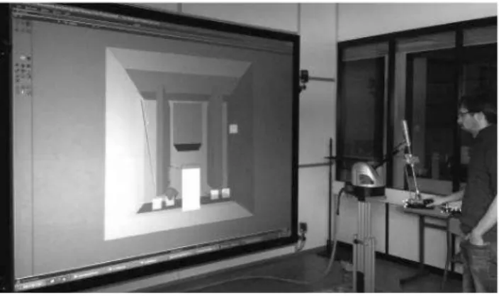
We have implemented the following simulations on our VR platform [9] (Fig. 8). The VR devices used here are a large screen using passive stereoscopy for the 3D visualization and immersion, an AR Track system for the user view-point capture and a Virtuose 6D 35-45 haptic device for the part handling.
The first simulation is a 3D instance of the 2D example used to illustrate the prin-ciples of our planning strategy in section 3. It has been used for development and allowed to test the collaboration of the planners. The second simulation shows a richer semantics of the environment (semantic attributes that describe the shape of objects and places). This allows showing how the control of the planning pro-cess, using the semantic information, increases the reliability of the planned path while reducing the processing time.
5.1 Semantic control and control sharing application
Simulation scene To test the multi-layer structure on the laboratory’s VR
plat-form, the environment used is a 3D instance of the environment given in section 3. This environment is a cubic workspace with four obstacles cluttering the scene (3 fixed and 1 moving). Different environment configurations have been tested moving the fixed obstacles to change the complex passages locations (O1and O2 are moved vertically and O3horizontally). The corresponding topological graphs are given in Fig. 9. This figure also illustrates the planning query in these envi-ronments. It aims at bringing a virtual object from a start point S in place P1to a goal point G in place P2. The topological paths found by the topological planner are also displayed in bold blue lines in the topological graphs.
Fig. 8. Simulation on VR platform S G B1,5 B2,7 B1,6 B2,8 B3,5 B3,7 B4,6 B4,8 B3,9 B3,10 B4,9 B4,10 P1 P1 P1 P2 P3 P4 P5 P7 P8 P6 P9 P10 P3 P3 P3 P3 P4 P4 P4 P4 P2 P2 S G T1,5 T2,7 T1,6 T2,8 T3,5 T3,7 T4,6 T4,8 T3,9 T3,10 T4,9 T4,10 P1 P1 P1 P2 P3 P4 P5 P7 P8 P6 P9 P10 P3 P3 P3 P3 P4 P4 P4 P4 P2 P2 a.Environment 1 b.Environment 2 S G T1,5 T2,7 T1,6 T2,8 T3,5 T3,7 T4,6 T4,8 T3,9 T3,10 T4,9 T4,10 P1 P1 P1 P2 P3 P4 P5 P7 P8 P6 P9 P10 P3 P3 P3 P3 P4 P4 P4 P4 P2 P2
a.Environment 1.
b.Environment 2.
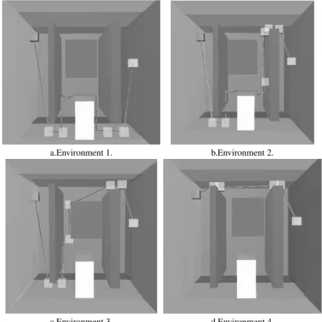
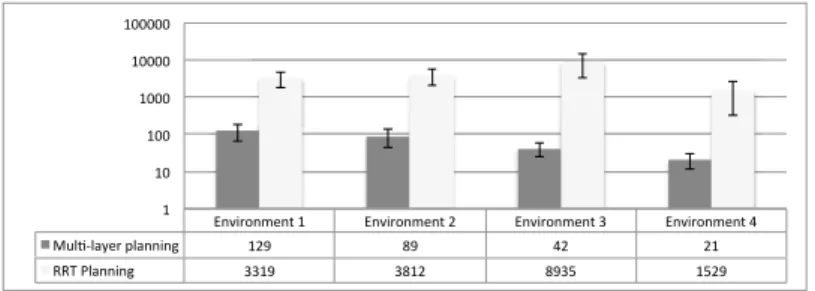
S G T1,5 T2,7 T1,6 T2,8 T3,5 T3,7 T4,6 T4,8 T3,9 T3,10 T4,9 T4,10 P1 P1 P1 P2 P3 P4 P5 P7 P8 P6 P9 P10 P3 P3 P3 P3 P4 P4 P4 P4 P2 P2 c.Environment 3 d.Environment 4Path planning Figure 10 shows the real path computed in the environment il-lustrated in Fig. 9. The manipulated object is the red cube and the targeted goal is the green one. The path is displayed in green. The paths on place P3avoid the mobile obstacle O4because of the RRT algorithm performed on this cluttered place. The number of random configuration used to find such paths is given in Fig.11. Depending on the crossed places and the paths that defined by the RRT algorithm the number of random configuration needed is between 21 (Environ-ment 4) and 129 (Environ(Environ-ment 1). When using the RRT algorithm only, defining similar path needs from 1529 (Environment 4) to 8939 (Environment 3) random configurations.
a.Environment 1. b.Environment 2.
c.Environment 3. d.Environment 4.
Fig. 10. Planning results
Path re-planning Figure 12 illustrates the topological re-planning including
real-time prediction of user’s intent. In Fig. 12.a, in the first step, the user seems to prefer the narrow passage. Predicting it, the topological path is recomputed taking
!"#$%&"'(")*+* !"#$%&"'(")*,* !"#$%&"'(")*-* !"#$%&"'(")*.* /0123145(%*614""$"7* +,8* 98* .,* ,+* ::;*<14""$"7* --+8* -9+,* 98-=* +=,8* +* +>* +>>* +>>>* +>>>>* +>>>>>*
Fig. 11. Average and standard deviation of number of random configurations used for path plan-ning in the design application
into account this intent. In Fig. 12.b, the user doesn’t follow the guidance along the geometrical path in the third topological step. Thus, the topological planner computes a new topological path. The path re-planning including fine planning process is performed enough fast to allow real-time interaction.
a.Re-planning in step 1. b.Re-planning in step 3. Fig. 12. Topological re-planning in environment 1
5.2 Shape as semantic information
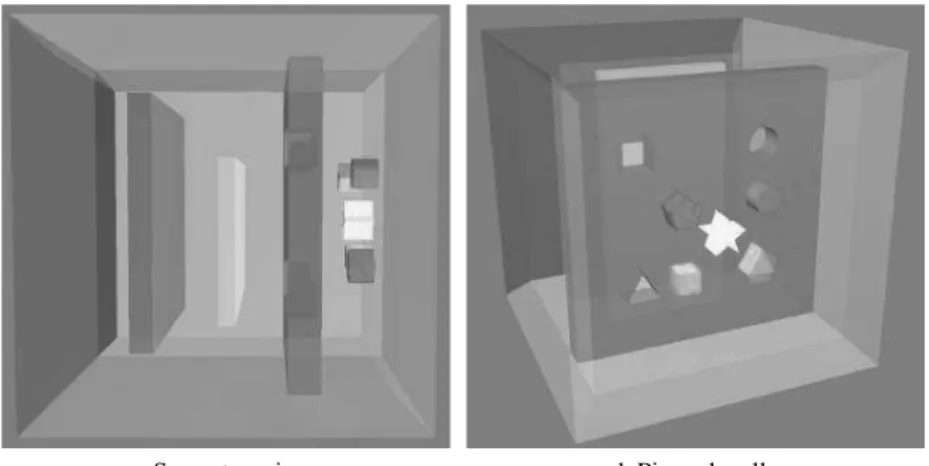
Simulation sceneThe simulation scene (Fig. 13) is made of a cubic workspace
divided in three large places by two walls (Fig. 13.a). The wall in the foreground is an obstacle with four holes (Fig. 13.b). Each hole has a characteristic shape (square, triangular, round and pentagonal). The wall in the background is an ob-stacle leaving a passage on each side (a large one on the bottom and a narrow one on the top in Fig. 13.a). A moving obstacle clutters the place between these two walls.
a.Scene top view. b.Pierced wall. Fig. 13. Shape application environment
The topological places of this environment are: the three large places, the two passages around the background wall (Fig. 13.a), and the holes through the fore-ground wall, each hole corresponds to a place (Fig. 13.b). The semantic attributes attached to the places are: ”low complexity” for the three large places; ”high complexity” for the large passage around the background wall, and ”very high” for the narrow one. The additional ”cluttered” semantic attribute is assigned to the places containing moving objects. Attributes are also set to the wall holes to describe their shape (”square”, ”triangular”, ”round” and ”pentagonal”). These shape attributes allow the automatic path planner finding an accurate topological path being guided according to the semantic information. However, to provide the VR user with topological path alternatives, shaped objects can cross the wall through differently shaped holes. The corresponding object/hole compatibility is given in Table 3.
Object\ Hole Circle Square Triangle Pentagon
Circle X X X
Square X X X
Triangle X X X
Pentagon X
Star X
Table 3. Object/hole compatibility
The planning query here consists in passing the two walls to move one of the shaped object (colored) from one side of the cube to the other.
Path planning Figure 14 shows the path (green rays) computed for the
(except the star object) is, the path planned crosses the first wall through the hole with the same shape. For the star object, as there is no hole with the same shape, the Topological path crosses the triangular hole and thus provide an inaccurate path that doesn’t allow to define non colliding path. Thus, to handle this query, the VR user have to move toward the pentagon hole to start a re-planning guided toward this shaped hole.
Fig. 14. Planning results for triangular object
The number of configuration randomly defined to find a path for each objects is given in Fig.15. To get such results, for the multi-layer planning, the non collision constraint have been relaxed in the topological milestones (explaining that the automatic path planner find a path with colliding milestones in the triangular hole for the star object). For the RRT planning, the number of random configuration used have been limited to one million. Thus, for the RRT planning the nearer to one million the average number of random configurations is, the higher the failing rate is.
!"#$%&' (&)*+,-)' ./0+#&' .*+#' 1#"+),%&' 20%34%+5&#'(%+))"),' 6778' 998:' 68:;' ;76<' 7;::' ==1'(%+))"),' >;6<?@' ;?6:??' <67?:' >::::::' >@>96@' >' >:' >::' >:::' >::::' >:::::' >::::::' >:::::::'
Fig. 15. Average and standard deviation of number of random configurations used for path plan-ning in the shapes application
Path re-planning Figure 16 illustrates the path re-planning in the case of the triangular object manipulation. Here, the user did not follow the haptic guidance along the geometrical path. In the first place, he moved toward the pentagonal hole starting thus the re-planning process. The resulting path goes through the pentagonal hole (Fig.16.a). In the middle place between the two walls, he moved toward the narrow passage, then the re-planned path goes that way (Fig.16.b). Thus, in both cases, a new multi-layer path planning is performed to take into ac-count the operator’s intents. Once the new Topological path defined the guidance is updated to assist the operator along is preferred path.
a.From first place. b.From middle place. Fig. 16. Interactive path re-planning
6
Conclusion
This paper presents a novel multi-layer architecture for interactive path planning in VR simulations. This architecture is based on a multi-layer environment model and a multi-layer planner. Each layer deals with specific information (semantic, topological and geometric). The contribution of such an architecture is two-fold : – First, it provides the user with real-time manipulation guidance by involving the semantic and topological information in the path planning process. The path planning process is accelerated by splitting the path in steps and then by adapting the geometric planning strategy to the local complexity of each step.
– Second, it integrates efficiently a human in the loop: path re-planning is com-puted based on real-time user’s intent prediction and motion control is shared by the user and the planner.
The interest of such a planner architecture had been demonstrated here with se-mantic information of the environment based on ”complexity”, ”shape” and ”clut-tering”. This information allowed this novel architecture to deal efficiently with an abstract example using only simple geometrical path planning techniques.
However, real manipulation task for industrial processes involves more complex semantic information (functional surface, multi-physics interactions, surfaces or material properties). Future work will be done to further define both the meaning-ful semantic information needed for such tasks and the corresponding planning strategies. For instance, in assembly tasks, sliding motions are commonly used. We are planning to develop interactive geometric path planning methods with contact. We also plan to enrich the topological and semantic layer of our environ-ment model in order to use our global architecture to plan paths with or without contact according to the functional context of the assembly tasks (or subtasks) to be performed. The proposed architecture meets the requirements for such seman-tic information.
Moreover, with an accurate semantic description, such a planner structure seems also well suited for off-line path planning allowing to rapidly find hard passages using the topological planning and to rapidly adapt the geometric planning strat-egy according to the local planning context.
Bibliography
Aarno, D., Ekvall, S., Kragic, D.: Adaptive virtual fixtures for machine-assisted teleoperation tasks. In: International Conference on Robotics and Automa-tion. pp. 1139–1144. IEEE (2005)
Abbink, D.A., Mulder, M.: Neuromuscular analysis as a guideline in designing shared control. Advances in haptics 109, 499–516 (2010)
Ahmadi-Pajouh, M.A., Towhidkhah, F., Gharibzadeh, S., Mashhadimalek, M.: Path planning in the hippocampo-prefrontal cortex pathway: An adaptive model based receding horizon planner. Medical hypotheses 68(6), 1411– 1415 (2007)
Anderson, S.J., Peters, S.C., Iagnemma, K., Overholt, J.: Semi-autonomous sta-bility control and hazard avoidance for manned and unmanned ground ve-hicles. Tech. rep., DTIC Document (2010)
CGAL: CGAL, Computational Geometry Algorithms Library (2014), http:// www.cgal.org
Dijkstra, E.W.: A note on two problems in connexion with graphs. Numerische mathematik 1(1), 269–271 (1959)
Dragan, A.D., Srinivasa, S.S.: A policy blending formalism for shared control. International Journal of Robotics Research (2013)
Fagg, A.H., Rosenstein, M., Platt, R., Grupen, R.A.: Extracting user intent in mixed initiative teleoperator control. In: American Institute of Aeronautics and Astronautics Intelligent Systems Technical Conference (2004) Fillatreau, P., Fourquet, J.Y., Le Bolloch, R., Cailhol, S., Datas, A., Puel, B.:
Using virtual reality and 3d industrial numerical models for immersive in-teractive checklists. Computers in Industry (2013)
Flemisch, F.O., Heesen, M., Hesse, T., Kelsch, J., Schieben, A., Beller, J.: To-wards a dynamic balance between humans and automation: authority, abil-ity, responsibility and control in shared and cooperative control situations. Cognition, Technology & Work 14(1), 3–18 (2012)
Ladev`eze, N., Fourquet, J.Y., Puel, B.: Interactive path planning for haptic assis-tance in assembly tasks. Computers & Graphics 34(1), 17–25 (2010) LaValle, S.M.: Planning algorithms. Cambridge University Press (2006) Li, M., Okamura, A.M.: Recognition of operator motions for real-time assistance
using virtual fixtures. In: Symposium on Haptic Interfaces for Virtual Envi-ronment and Teleoperator Systems. HAPTICS. pp. 125–131. IEEE (2003) Loizou, S.G., Kumar, V.: Mixed initiative control of autonomous vehicles. In:
In-ternational Conference on Robotics and Automation. pp. 1431–1436. IEEE (2007)
Lozano-Perez, T.: Spatial planning: A configuration space approach. Transactions on Computers 100(2), 108–120 (1980)
Marayong, P., Li, M., Okamura, A.M., Hager, G.D.: Spatial motion constraints: Theory and demonstrations for robot guidance using virtual fixtures. In: International Conference on Robotics and Automation. vol. 2, pp. 1954– 1959. IEEE (2003)
Ta¨ıx, M., Flavign´e, D., Ferr´e, E.: Human interaction with motion planning algo-rithm. Journal of Intelligent & Robotic Systems 67(3-4), 285–306 (2012)
Weber, C., Nitsch, V., Unterhinninghofen, U., Farber, B., Buss, M.: Position and force augmentation in a telepresence system and their effects on perceived realism. In: EuroHaptics conference and Symposium on Haptic Interfaces for Virtual Environment and Teleoperator Systems. World Haptics. pp. 226– 231. IEEE (2009)
You, E., Hauser, K.: Assisted teleoperation strategies for aggressively controlling a robot arm with 2d input. Robotics: Science and Systems VII p. 354 (2012) Yu, W., Alqasemi, R., Dubey, R., Pernalete, N.: Telemanipulation assistance based on motion intention recognition. In: International Conference on Robotics and Automation. pp. 1121–1126. IEEE (2005)