UNIVERSITÉ DE SHERBROOKE
Faculté de génie
Département de génie chimique et de génie biotechnologique
Développement d’un modèle CFD et son
utilisation afin de mieux comprendre et
contrôler le phénomène de la production de la
mousse dans un contexte de procédés
biotechnologiques
Thèse de doctorat
Spécialité : génie chimique
Gabriel St-Pierre-Lemieux
Sherbrooke (Québec) Canada
MEMBRES DU JURY
Pierre Proulx
DirecteurDenis Groleau
CodirecteurAlain Garnier
ÉvaluateurRyan Gosselin
ÉvaluateurFrançois Gitzhofer
ÉvaluateurRÉSUMÉ
Que ce soit lorsqu’on fait cuire des pâtes ou lorsqu’on prend un bain, la mousse est présente dans un grand nombre d’activités quotidiennes. La formation de cette structure composée de bulles de gaz contraintes implique des phénomènes touchant plusieurs disciplines. Sa présence dans un grand nombre de procédés et la complexité des phénomènes entourant sa création ont suscité beaucoup d’intérêt et beaucoup de travail a déjà été fait afin de mieux la comprendre et de la contrôler. Son importance dans les procédés biotechnologiques n’est pas moindre, que ce soit lors de la production d’hydrocarbures à l’aide d’algues ou lors d’une simple fermentation en bioréacteur. Les problèmes entraînés par la mousse lors de nombreuses fermentations ont poussé le développement de méthodes pour contrôler sa production ou son niveau de production ou d’accumulation. Ces méthodes sont regroupées en deux grandes familles : les méthodes utilisant un adjuvant (antimousse chimique) que l’on ajoute au milieu et les méthodes mécaniques. Lors du développement des méthodes mécaniques, peu de gens se sont penchées sur les phénomènes physiques les entourant, reléguant leur compréhension à d’autres champs de recherche. Ce qui est un peu malheureux, puisque la physique associée à la production de mousse est relativement bien comprise. La présente thèse attaque le phénomène de moussage en biotechnologie avec un tout nouvel angle en ficelant les connaissances existantes en physique et en génie chimique pour produire des outils essentiels à son étude. Ayant en son coeur l’objectif d’étudier les méthodes de contrôle de la mousse lors d’une fermentation cette thèse décrit les premiers pas vers des modèles utilisant la dynamique des fluides (CFD) pour mieux comprendre les méthodes de contrôle. Elle débute par une revue de la littérature couvrant la mousse en général, sa présence en bioréacteur et ses impacts, et ce, sans faire de compromis sur les phénomènes physiques. Par la suite, la longue voie vers un modèle basé sur la CFD est entamée avec le développement d’outils visant à solutionner les problèmes reliés à l’étude d’une mousse sélectionnée. En passant par la production d’un maillage essentiel aux méthodes employées, jusqu’aux outils d’étude d’équilibre des populations.
La thèse se termine par la présentation d’une modélisation des cônes inversés, utilisés comme dispositifs afin de briser la mousse. Il s’agit, grosso modo, de mécanismes rotatifs qui pompent le fluide et le pulvérisent sur la périphérie. Le modèle est basé sur les propriétés non newtoniennes de la mousse et cherche à établir son interaction avec le brise-mousse mécanique. Plusieurs phénomènes intéressants furent observables grâce à ce modèle, dont les limites de l’application d’un tel appareillage et le décrochage de la mousse menant à formation d’un motif de pulvérisation en forme d’anneaux.
ABSTRACT
Development of a CFD model and its use to better understand and control the phenomenon of foam production in a context of biotechnological processes Either during pasta cooking or while taking a relaxing bath, foam is observed in many daily activities. Foam is a complex constrained bubble network and its formation implies different phenomena associated with many disciplines. The presence of foam in numerous processes and the complexity of the phenomena surrounding foaming have attracted much interest from the scientific community. A lot of work has been done to understand foam structure, the forces involved and foam collapsing. Its importance in biotechnological processes cannot be neglected. Foaming influences the production of algae, fermentation operations conducted in bioreactors and numerous food-related processes. The problems created by foam formation in many fermentations have forced the development of various control methods. These methods are divided into two large groups: the ones that use a chemical adjuvant (antifoam) added to the broth and the ones that use mechanical devices/interactions. While numerous new mechanical methods have been developed, the physics behind their efficiency has been poorly addressed.
This thesis focuses on the foaming phenomenon in biotechnology using a whole new angle. The thesis’ overall objective is the study of the various foam control methods that are used during bioreactor operations. The thesis describes how computational fluid dynamics (CFD) may be used to better understand foam control strategies . The present work advances the use of CFD to understand foam behaviour and could be considered as a basic step for futher model developments. The first part of the thesis is a literature review which describes our general knowledge on foam and on the phenomenon of foaming, then, it goes into detail regarding the influence of foaming and how foaming may be controlled during bioreactor operations. To develop the model, interesting and usefull tools were generated in the course the studies.
Finally, the thesis ends with a section that focuses on the modeling of inverted cone foam breakers. Such foam breakers are rotating mechanisms which pump the foam in and then spray it around. The model is based on the non-Newtonian property of foam and seeks to establish how foam interacts with the foam breaker. Interesting observations have been made using the model, including the limits of its application together with an interesting spray pattern formed by the ejected foam.
REMERCIEMENTS
Making this thesis was a long project that took years and tears. Even if there was some hard time, I was never alone and completing it would not have been possible without a lot of help. Rare was the occasion to fully thank all the people that helped me. Caring, kind and (most of the time) wise, they allowed me to go over all the obstacles.
I would start by mentioning those who kept food on my table all along this project. Most of the work was financially supported by a Canada Research Chair grant attributed to Denis Groleau and managed by the Natural Sciences and Engineering Council of Canada (NSERC).
I should also give credit to my parents, with the addition of the St-Pierre and the Lemieux family who gave at numerous occasions spontaneous monetary support. I would thank all the Lemieux and the St-Pierre, naming all of them would take more pages than I am allowed. None less, I will obviously thank the three more involved family members, my father, Réjean Lemieux, my mother Brigitte St-Pierre and my brother Maxime St-Pierre Lemieux. In all long therm project, there is hardship. Without my mother, my father and my brother, my very soul would have been broken many times. If I’m standing, smiling in the face of difficulties, it’s because of you guys.
I want to give a special mention to Pauline St-Pierre and Léon St-Pierre, who gave me a lot of courage and contributed a lot to make the person I became.
I really appreciate all the help I received that contributed directly to my works. My supervisors, Pierre Proulx and Denis Groleau, who not only help me through the PhD, but also made me a better person, ready for the great number of challenge that awaits me. There is also Jocelyn Veilleux who help me to update my mathematical skill so I could survive a PhD in Engineering. Nady Brady, with whom I worked shortly, but learned much about teaching. Marc G. Couture and his son Alexandre Couture, who produced the 3d printed geometry and a little reactor for me to do my first CFD models.
I also want to thank the teams, peoples with whom I worked every day. Thanks to the Pierre marvelous team and the Martin team with whom I not only shared an office but also slice of life. I also appreciate the few time I work closer to the Denis team in the brand-new lab !
I will then finish by few word for Ehsan Askari, who was more a brother at arms than a simple colleague. He lived with me, failure, success, tear and laughter. We, together, pulled some wonderful accomplishments. I consider you.
TABLE DES MATIÈRES
1 Introduction 1
1.1 Contexte . . . 1
1.2 Définition de projet et objectifs . . . 3
1.3 Objectifs . . . 5
1.4 Contributions . . . 6
1.5 Structure de la thèse . . . 7
2 Article 1 : Introduction on Foam and its Impact in Bioreactors 9 2.1 Résumé . . . 10
2.2 Abstract . . . 10
2.3 Introduction . . . 11
2.4 Physics of Foam . . . 11
2.4.1 Definition . . . 11
2.4.2 Surface and Drainage . . . 15
2.4.3 Apparent Viscosity . . . 18
2.5 Foaming in Bioreactors . . . 19
2.5.1 Consequences . . . 19
2.5.2 Controlling Foam Production . . . 21
2.6 Controls Using Anti-foaming Agents . . . 23
2.6.1 Mechanism . . . 23
2.6.2 Influence of Anti-foaming Agents on the Fermentation . . . 25
2.7 Foam-Control Using Mechanical Means . . . 26
2.7.1 Foam Breakers . . . 26
2.8 Advances in Computer-Assisted Research . . . 31
2.9 Conclusion . . . 32
2.10 Acknowledgments . . . 33
3 Script mailleur 35
3.1 Introduction . . . 36
3.2 Usage . . . 37
3.3 Description . . . 37
3.3.1 Base Structure . . . 37
3.4 Settings Arguments and Examples . . . 40
3.4.1 The DIVI global variable . . . 40
3.4.2 The RQUAD global variable . . . 41
3.4.3 The HLAY global variable . . . 41
3.4.4 The SHAFT global variable . . . 42
3.4.5 The IMPELLERCUT global variable . . . 42
3.4.6 The SQRRATIO global variable . . . 42
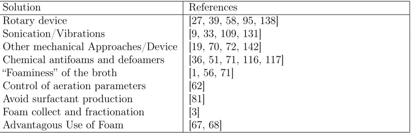
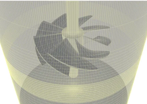
3.5 Produced Geometry . . . 43
3.5.1 8 blades turbine . . . 43
3.5.2 Conic Foam Breaker . . . 44
3.5.3 Rushton Impeller . . . 45
3.5.4 Electrolytic Cell . . . 46
4 Article 2 : Application of Extended Quadrature Method of Moments for Simulation of Bubbly Flow and Mass Transfer in Gas-Liquid Stirred Tanks 49 4.1 Résumé . . . 50 4.2 Abstract . . . 51 4.3 Introduction . . . 53 4.4 Experimental setup . . . 55 4.5 Numerical model . . . 56
4.5.1 Governing flow equations . . . 56
4.5.2 Interfacial momentum exchange . . . 57
4.5.3 Turbulence model equations . . . 58
TABLE DES MATIÈRES xi
4.5.5 Interphase Oxygen Mass Transfer . . . 62
4.6 Tank specifications and numerical technique . . . 64
4.7 Result and Discussion . . . 66
4.7.1 Rushton turbine . . . 66
4.7.2 New Brunswick bioreactor . . . 67
4.8 Conclusion . . . 72
4.9 Acknowledgement . . . 73
5 Article 3 : Modeling of Non-Newtonian Flow in an Inverted Cone Foam Breaker 81 5.1 Résumé . . . 82
5.2 Abstract . . . 82
5.3 Introduction . . . 83
5.4 Methods . . . 84
5.5 Results and Discussion . . . 86
5.5.1 Water . . . 86
5.5.2 Foam . . . 88
5.6 Concluding Remarks . . . 91
6 Conclusion 93 6.1 Travaux futurs . . . 94
A SuperMarine Commented Code 95
B Algorithme d’Interfoam 101
LISTE DES FIGURES
1.1 L’Univers rapproché avec ses vides et ses lamelles forme une structure très
similaire à la mousse[120]. . . 2
1.2 Distribution quinquaniale des Brevets (donnés de Google Patent.) . . . 4
2.1 Four-channel Plateau Border junction . . . 12
2.2 (A) Kelvin’s foam with rhombic dodecahedron and (B) WWeaire and Phelan foam with the pyritohedron (magenta) and the hexagonal trapezohedron (gray) . . . 13
2.3 Foaming Control / Troubleshooting . . . 21
2.4 A) Paddle and C) needle foam breakers from Deshpande et al.[39] B) Cone foam breaker from Cook et al [? ] D) A simple bar foam breaker . . . 30
3.1 Orthogonalité et asymétrie des mailles. [57] . . . 35
3.2 Meshing of a Turbine produced using SuperMarine . . . 36
3.3 The Pre-processing Steps of a Typical Mixer Case . . . 37
3.4 The code structure . . . 38
3.5 Vertices Ordering . . . 38
3.6 Marine impeller without the correction after a rotation. . . 39
3.7 Rotation Correction . . . 40
3.8 Meshing of a Rushton Impeller . . . 45
3.9 Meshing of an Electrolytic Cell . . . 46
4.1 Simple modèle de fraction liquide. . . 50
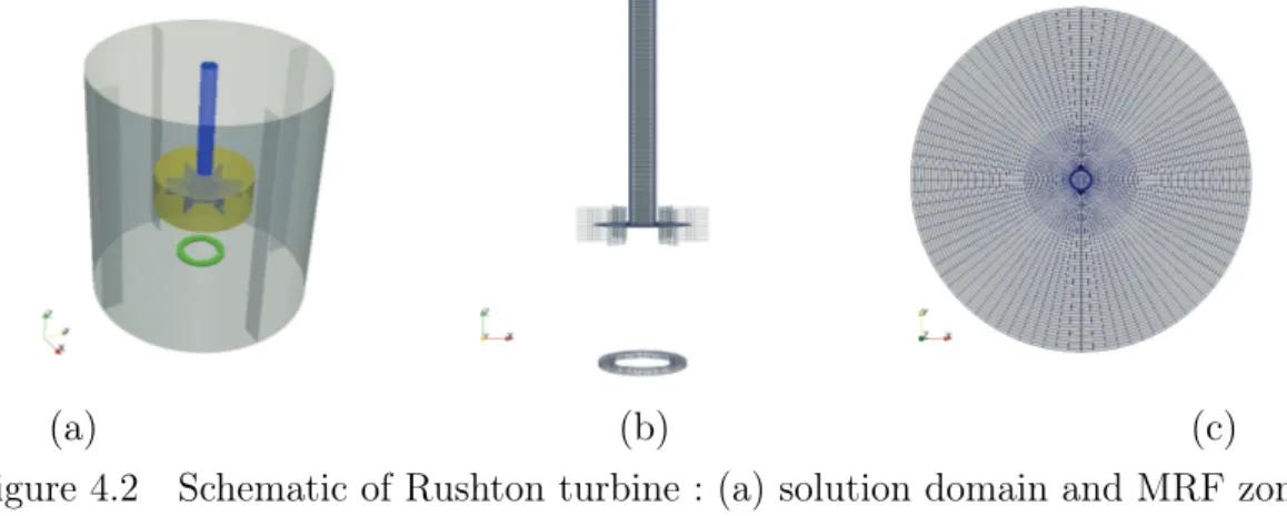
4.2 Schematic of Rushton turbine : (a) solution domain and MRF zone, (b) structured mesh in impeller and shaft with location of the sparger ring and (c) front view of the structured mesh . . . 64
4.3 Schematic of bioreactor : (a) solution domain and MRF zone, (b) unstructu-red mesh in impeller and shaft with sparger location and (c) front view of the unstructured mesh . . . 65
4.4 Prediction of water axial (uz) and radial velocity (ur) at r/R = 0.37 for Rushton turbine . . . 67
4.5 Contour map provided by CFD-PBM in Rushton reactor at ω = 513 rpm (a) air phase fraction, (b) air velocity vectors, (c) bubble size (Sauter diameter) 68
4.6 The flow condition in Rushton reactor based on [90] for ω=513 rpm . . . . 69
4.7 DO evolution for (a) ω=50 rpm, (b) ω=150 rpm, (c) ω=300 rpm, (d) ω=600 rpm . . . 70
4.8 The flow condition in Bioreactor based on [90] for ω=50 rpm, ω=150 rpm, ω=300 rpm and ω=600 rpm . . . 71
4.9 Experimental images in stirred tank for (a) ω=50 rpm, (b) ω=150 rpm, (c) ω=300 rpm, (d) ω=600 rpm . . . 71
4.10 Contour of averaged-time gas hold-up along the plane located in the middle of the reactor (a) ω=50 rpm, (b) ω=150 rpm, (c) ω=300 rpm, (d) ω=600 rpm 74 4.11 Averaged-time gas velocity vectors along the plane located in the middle of the reactor ( (a) ω=50 rpm, (b) ω=150 rpm, (c) ω=300 rpm, (d) ω=600 rpm 75 4.12 Contour of averaged-time local Sauter diameter along the plane located in the middle of the reactor (a) ω=50 rpm, (b) ω=150 rpm, (c) ω=300 rpm, (d) ω=600 rpm . . . 76
4.13 Dynamic Number Density Function (NDF) in water zone for 50 rpm in (a) δt=1 s, (b) δt=2 s, (c) δt=3 s, (d) δt=4 s . . . 77
4.14 Dynamic Number Density Function (NDF) in water zone for 150 rpm in (a) δt=1 s, (b) δt=2 s, (c) δt=3 s, (d) δt=4 s . . . 78
4.15 Dynamic Number Density Function (NDF) in water zone for 300 rpm (a) δt=1 s, (b) δt=2 s, (c) δt=3 s, (d) δt=4 s . . . 79
4.16 Dynamic Number Density Function (NDF) in water zone for 600 rpm (a) δt=1 s, (b) δt=2 s, (c) δt=3 s, (d) δt=4 s . . . 80
5.1 Water Ligaments Formed at 750 rpm . . . 83
5.2 Meshing of the Case . . . 85
5.3 Torque Applied on the Geometry . . . 87
5.4 Flow Rates of Water . . . 87
5.5 Ligaments of Water when Filled at 500 rpm . . . 88
5.6 Flow Rate of Water in Time . . . 89
5.7 Mass of Foam Adsorbed to the Geometry . . . 89
5.8 Shear Rate Response of the Shaving Cream . . . 89
LISTE DES FIGURES xv
5.10 Some Observations About Foam Behaviour . . . 91
5.11 Velocity of Water Close to the Inner Cone Wall . . . 91
5.12 Velocity Close of Foam to the Inner Cone Wall . . . 91
B.1 Interfoam . . . 101
LISTE DES TABLEAUX
2.1 Potential Solutions for the Control and Mitigation of Foam Formation . . . 31 3.1 Quick Instructions . . . 43 4.1 Overview of mass transfer coefficients used in the model . . . 63 4.2 The main characteristics of the test cases investigated in this study ; ω, the
rotational speed (rpm) and KL, the mass transfer coefficient (m/s) . . . 65
4.3 Overview of divergence schemes used in fvScheme dictionary . . . 66 5.1 H.-B. Constant values used . . . 84
LISTE DES SYMBOLES
Symbole Definition Unités
Aii Aire ii m2
CD Coefficient de trainée sans unité
G′,G′′ Décomposition des contraintes de cisaillement P a
Hii Hauteur ii m
Kii Regroupement de termes (lisibilité)
Rii Rayon ii rad
Q Débits volumique m3/s
u[x,y,z] Vecteur de la vélocité m/s
¯
u Moyenne de la magnitude de la vélocité dans le temps m/s ⟨u⟩ Moyenne de la magnitude de la vélocité dans l’espace m/s a Aire spécifique de l’interface m−1 cf Coefficient de croissance de l’aire sans unité
dii Diamètre ii, sans subscript des bulles m
u Vecteur de la Vitesse m/s
Eo Nombre d’Eotvos sans unité
Re Nombre de Reynolds sans unité
Sc Nombre de Schmidt sans unité
Sh Nombre de Sherwood sans unité
t Temps s
g Vecteur de la gravité (constante dans ce document) g
γ0 Stress de Rupture P a ∗ s
˙γ Contrainte de cisaillement P a
ω Vitesse angulaire rad/s
ρ Densité kg/m3
ϕ Une fraction, dans ce document ϕliq est la fraction liquide sans unité
Ξ Position relative sur l’axe des ordonnées sans unité ξ Taille adimensionnel des vortex sans unité
τ Taux de cisaillement P a ∗ s
τ0 Contrainte de cisaillement P a ∗ s
P Pression P a
x,y,z Représente chaque axes dans R3 (ordonnée, absice, cote) m
LISTE DES ACRONYMES
Acronyme Definition
CFD Computational Fluid Dynamic (Mécanique des fluides numérique) FVM Finite Volume Method (Méthodes des volumes finis)
TFM Two Fluid Model (Modèle de deux fluides)
PBM Population Balance Modelling (Modélisation par équilibre des populations) CM Classes Method
MOM Mehods Of Moments
QMOM Quadrature Methods Of Moments
DQMOM Direct Quadrature Methods Of Moments EQMOM Extended Quadrature Methods Of Moments QBMM Quadrature Based Methods Of Moments MRF Moving Reference Frame (Référenciel mouvant) NDF Near Density Function (Fonction de densité) DO Dissolved Oxigen (Oxygène dissou)
PIV Particle Image Velocimetry (Velocimetry par imagerie de particules)
CHAPITRE 1
Introduction
1.1
Contexte
La mousse est essentiellement un ensemble de bulles gazeuses séparées par de minces parois de liquide. Que ce soit avec un savon, la bière ou l’écume des rivières, la présence de mousse est vue comme banale et provoque habituellement peu de questionnements. Les mécanismes à la base de la formation de la mousse sont très répandus et peuvent être présents à des échelles surprenantes (Figure 1.1). Par exemple, les interactions entre la matière et la matière sombre forcent la matière de l’univers à adopter des formes ressemblant beaucoup aux membranes présentes dans la mousse. Puisque la formation de la mousse est plutôt commune, c’est surtout lorsqu’elle est impliquée dans un procédé de fabrication ou de transformation que son importance est remarquée et devient souvent problématique. Pour beaucoup, c’est lorsqu’il est nécessaire de comprendre son origine et son comportement qu’elle perd sa simplicité apparente. En effet, la production de mousse est un phénomène complexe de par sa structure, sa composition, son caractère thixotropique et son comportement non newtonien. Elle est soit à la base d’un procédé de production soit un simple sous-produit soit carrément une nuisance. En biotechnologie, elle peut, par exemple, permettre d’extraire des substances d’un milieu de production, grâce à un procédé appelé fractionnement, tout comme elle peut forcer l’arrêt d’une fermentation en bloquant la circulation de l’air et/ou en favorisant une contamination.
Les interactions complexes présentes dans la structure de la mousse ont très rapidement attiré l’intérêt de physiciens et mathématiciens de renom. Un système simple, que beaucoup connaissent, est celui de deux bulles en équilibre, tel qu’illustré par une équation développée par Young et Laplace au début du 18e siècle [89, 167]. Laplace, reprenant une hypothèse émise par Hauksbée, a décrit dans les suppléments de son livre "Traité de mécanique céleste" ni plus ni moins le phénomène de la tension de surface. Intrigué par ces travaux, Joseph Plateau a décidé d’observer des structures plus complexes, composées d’un grand nombre de bulles. Il a été capable de produire une série d’observations sur les structures pour en tirer des lois très simples [119]. Ses observations seront prouvées mathématiquement beaucoup plus tard, en 1974, par Jean Taylor (ne pas confondre avec Brook Taylor) [143].
Figure 1.1 L’Univers rapproché avec ses vides et ses lamelles forme une structure très similaire à la mousse[120].
D’autres mathématiciens célèbres, comme William Thomson, ont étudié diverses méthodes pour séparer l’espace tout en minimisant les surfaces utilisées pour la découper. William Thomson a établi sa conjecture en observant la mousse et son comportement dans un dispositif appelé cube de Plateau [146]. Cette conjecture sera contredite beaucoup plus tard, dans les années 1990, par des modèles informatiques développés par Weaire et Phelan [164]. Le phénomène le plus important pour la stabilité de la mousse, l’effet Marangoni, fut observé par James Thomson (le frère de William) dans les larmes de vin [145]. Willard Gibbs a complété la théorie reliée à ce phénomène quelques années plus tard [54].
La mousse génère un grand nombre de difficultés lorsque la production du produit d’intérêt se fait dans des bioréacteurs (ou fermenteurs). Pour de nombreux procédés de fermentation, il est important de limiter la formation et l’accumulation de mousse. Bien que le phénomène ait été bien décrit physiquement, dans le contexte d’une fermentation, il est beaucoup plus difficile de bien suivre un tel phénomène. En effet, il est difficile de prévoir les propriétés de la mousse lorsqu’un micro-organisme X et un bioréacteur Y interagissent avec un milieu de production Z. Par exemple, un micro-organisme peut produire des surfactants dans des conditions particulières, provoquant ainsi la formation surprise de mousse. Un phénomène qui peut arriver, par exemple lors de la mise à l’échelle d’un procédé de fermentation. Afin de limiter la présence de mousse, un grand nombre de méthodes de contrôle de la
1.2. DÉFINITION DE PROJET ET OBJECTIFS 3 mousse ont été développées au cours des dernières décennies. Puisque le phénomène survient fréquemment, parfois à la surprise de l’opérateur, il est courant de voir deux mécanismes communs de contrôle intégrés aux bioréacteurs. Le premier est de nature mécanique et est constitué d’une simple tige, attachée au cardan de la turbine, et le deuxième est de nature chimique, i.e. un fluide pompé dans le milieu lorsque la mousse atteint un certain niveau de dangerosité. Ces fluides sont constitués d’un agent antimousse, aussi appelé agent anti-moussant. Notons que certains auteurs font une distinction entre agent antimousse et agent anti-moussant. Ces deux mécanismes sont les représentants des deux grandes familles de méthodes de contrôle de la mousse développées jusqu’ici.
Malheureusement, le contrôle de la mousse est souvent fait afin de régler rapidement un problème important de mousse associé à un procédé de production particulier Les solutions ainsi développées sur une base ad hoc ne font pas souvent l’objet de publications. Il y a, donc, un nombre élevé de « brevets » et de secrets industriels (Figure 1.2), mais peu d’articles scientifiques consacrés au contrôle de la mousse dans le grand monde de la fermentation microbienne. Cette pauvreté apparente d’informations touchant le domaine de la biotechnologie n’est cependant pas reflétée dans les domaines de la physique et de la chimie, où les agents antimousses ont fait l’objet de nombreuses études. Des recherches comme celles effectuées par Denkov, ont apporté des informations précieuses sur le drainage et l’affaissement des lamelles causées par les agents antimousses [37]. Ces avancées récentes ont permis de comprendre beaucoup mieux l’action des agents antimousses sur les interfaces ainsi que leurs interactions avec les surfactants déjà présents. Contrairement aux agents antimousses, les méthodes mécaniques n’ont été l’objet que d’études très appliquées. Combiné aux secrets industriels, cela crée un déficit d’informations important pour l’exploration de nouvelles approches visant le développement de méthodes mécaniques (brise-mousses) plus efficaces avec les procédés de fermentation.
1.2
Définition de projet et objectifs
La structure de la mousse et les forces impliquées dans sa formation et sa destruction sont bien maîtrisées dans la littérature, d’après notre évaluation. Cette maîtrise, doublée de l’utilisation de la technologie, a permis des avancées notables dans l’efficacité des antimousses chimiques et dans notre compréhension de leur activité. Cependant, dans le cas des méthodes des contrôles mécaniques, les progrès effectués ont fait l’objets de très peu de publications. Bien que généralement moins employées que les méthodes basées
sur les antimousses chimiques, les méthodes de contrôle mécaniques demeurent d’une importance cruciale. Les méthodes mécaniques peuvent être utilisées en combinaison avec les antimousses chimiques pour une plus grande efficacité. De plus, les méthodes mécaniques peuvent parfois être les seules solutions viables pour contrôler la mousse lors d’une fermentation. Leur efficacité est reliée à leur capacité à appliquer sur la mousse des forces de cisaillement ou de pression, tout en utilisant le moins d’énergie possible. L’étude de la dynamique des fluides associée aux brise-mousses mécaniques nous semblait donc être un outil essentiel pour optimiser leur utilisation. Par chance, de nombreuses ressources étaient disponibles afin d’envisager une recherche axée sur l’utilisation de méthodes numériques. Ces méthodes ont déjà été utilisées lors d’études se concentrant sur le drainage de la mousse et sur l’injection de mousses de polymères. Il a donc semblé très opportun d’explorer cette voie afin de développer des modèles de brises-mousses mécaniques et d’étudier leurs interactions avec la mousse. La présente thèse a pour but d’étudier des méthodes de contrôle de la mousse dans des conditions simulant la présence de mousse en bioréacteur, en particulier grâce à l’emploi de méthodes mécaniques.
1.3. OBJECTIFS 5
1.3
Objectifs
– Transférer les connaissances disponibles sur la mousse au domaine bio-technologique : La revue de littérature présentée dans ce document avait comme objectif de simplifier l’intégration des connaissances acquises sur la mousse dans le domaine de la physique, principalement, à la biotechnologie.
– Simplifier l’approche numérique au problème du contrôle de la mousse : L’approche numérique a été très rarement employée pour les problèmes relatifs à la mousse. Un des objectifs de la thèse était donc de préparer un modèle simple, fiable et facile a reproduire. Cet objectif a été rempli de trois façons : premièrement, une méthode de maillage aisée a été mise en place grâce aux scripts présentés dans cette thèse. Le maillage est une étape très demandante, mais grâce aux scripts incluses dans la thèse, un chercheur peut rapidement préparer un cas semblable pour une contre-étude ou même pousser les idées présentées plus loin. Deuxièmement, des modèles mathématiques ont été développés. Ces modèles seront disponibles, libres et pourront, non seulement être étudié, mais aussi directement utilisé pour des cas semblables. Finalement, un cas présentant un modèle complet a été produit. La méthode de travail, ainsi que le chemin parcouru est donc accessible aux autres chercheurs pour accélérer leurs propres études sur le comportement de la mousse. Il est possible d’utiliser la même démarche pour d’autres géométries, comme un bar ou un disque, qui pourrait être intéressant pour une application particulière.
– Exploiter les connaissances et les outils technologiques dans le cadre d’une application réaliste d’un brise-mousse mécanique : En utilisant les connais-sances acquises, ainsi que les outils développés et à notre disposition, un cas complet et réaliste a été préparé. Il s’agit d’une des rares applications de la Mécanique des fluides numérique (CFD) au problème de la mousse et une première en ce qui concerne des brise-mousses mécaniques. Les résultats numériques correspondent aux résultats obtenus en laboratoire et prouvent que, bien que la mousse soit complexe, il est possible de suivre son évolution grâce à la CFD.
1.4
Contributions
– Production d’une revue de littérature multidisciplinaire.
Alors que plusieurs revues discutent des antimousses chimiques et que celles couvrant la mousse focalisent sur les phénomènes physiques de la mousse, la revue de littérature qui va suivre recentre les discutions autour du domaine de la biotechnologie. La revue se place donc entre les revues existantes en physique et les revues diverses associées à la biotechnologie, établissant ainsi un lien qui était manquant.
– Développement d’outils numériques des bilans des populations.
Les limites logicielles ainsi qu’un espoir d’intégration futur a des problèmes impli-quant la synérèse a poussé l’appui aux recherches de mes collègues sur des modèles statistiques de distribution de bulles. Les modèles développés ont permis de suivre l’évolution du transfert d’oxygène dans un bioréacteur. Ces mêmes modèles pourraient être utilisés d’une manière très intéressante pour suivre l’évolution de la fraction liquide de la mousse.
– Développement d’outils numériques pour la production automatique de maillages.
Disponible au public sur github :
– Spationaute/SuperMarine : SuperMarine v0.3
Lemieux,G. St-Pierre - Proulx,P.
Zenodo - 2018 - DOI : 10.5281/zenodo.1237962
En plus d’être utilisé par les articles présentés dans cette thèse, le script a été aussi employé dans la publication suivante :
– Simulation of bubbly flow and mass transfer in a turbulent gas-liquid stirred tank with CFD-PBM solver in OpenFOAM : EQMOM application
Mahvelati,E. Askari - Lemieux,G.St-Pierre - Vieira,C.Braga - Litrico,G. - Proulx,P. AIP Conference Proceedings - 2018 - DOI : 10.1063/1.5043674
– Modelling of Bubbly Flow Using CFD-PBM Solver in OpenFOAM : Study of Local Population Balance Models and Extended Quadrature Method of Moments Applications
Mahvelati,E. Askari - Alberto Passalacqua - Proulx,P.
ChemEngineering - 2018 - DOI : 10.3390/chemengineering2010008
– Application sur un cas réaliste de brise-mousse mécanique.
Un modèle numérique d’un brise-mousse mécanique a été produit avec succès. Le modèle permet de suivre le comportement de la mousse dans une géométrie
intéres-1.5. STRUCTURE DE LA THÈSE 7 sante comportant un effet de pulvérisation. Les forces impliquées dans le phénomène ainsi que certains effets uniques des fluides non newtoniens ont été observés.
1.5
Structure de la thèse
La thèse attaque de front l’ensemble des disciplines nécessaire pour la compréhension des phénomènes liés à la mousse. Les articles présentent divers résultats axés sur le développe-ment d’outils exploitant les connaissances déjà développées dans d’autres domaines. Par conséquent, l’ensemble de la thèse peut être vue comme une tentative de rapatrié le savoir et de le réappliqué sur le problème de la mousse.
Le présent document est organisé de cette façon :
– Le chapitre 2 présente une revue de littérature qui documente plusieurs concepts de base de la mousse et les impacts de sa présence dans les bioréacteurs.
– Le chapitre 3 est l’introduction au manuel d’instructions publié avec le script produi-sant des maillages.
– Le chapitre 4 est un article qui concerne l’application d’une méthode statistique, nouvellement développée, pour suivre les bulles dans un bioréacteur.
– Le chapitre 5 est un article qui concerne l’étude des brise-mousses mécaniques en forme de cônes inversés.
– Le chapitre 6 est la conclusion de la thèse.
– Annexe A : Des exemples de paramètres pour le script produisant des maillages incluant ceux des cônes inversé.
CHAPITRE 2
Article 1 : Introduction on Foam and its
Im-pact in Bioreactors
– Gabriel St-Pierre-Lemieux : Département de génie chimique et de génie biotech-nologique, Université de Sherbrooke, QC, Canada
– Denis Groleau : Département de génie chimique et de génie biotechnologique, Université de Sherbrooke, QC, Canada
– Pierre Proulx : Département de génie chimique et de génie biotechnologique, Université de Sherbrooke, QC, Canada
Date de soumission : 01 Septembre 2019, Date de Publication : 01 Novembre 2019 Revue : Canadian Journal of Biotechnology
Titre en francais : Introduction sur la mousse et son impact dans les bioréacteurs
2.1
Résumé
La formation de mousse dans les bioréacteurs, ou même dans tout autre type de réacteurs est un sujet intéressant impliquant de nombreuses disciplines. Les phénomènes impliqués dans la génération de la mousse ont déjà fait l’objet d’un grand nombre d’études, cependant leurs liens ne sont pas toujours évidents pour des chercheurs qui commencent tout juste à s’intéresser au sujet. Cette revue a donc comme objectif de les relier pour faciliter leurs intégrations aux études des phénomènes reliés à la mousse, et ce, dans le contexte d’une fermentation en bioréacteur.
2.2
Abstract
Foam formation in bioreactors (fermenters) and other types of reactors is a highly interesting topic that touches several disciplines. All of the phenomena involved in foam formation have been the subject of many studies, but their relationships are still not obvious to newcomers. This review aimed to give the reader a good background for understanding the various phenomena involved in foam formation, especially in bioreactors. Hopefully, this would give the reader the tools necessary to access any needed information about foaming, a task that can be difficult without such a basic knowledge.
2.3. INTRODUCTION 11
2.3
Introduction
Foam formation is observed in many processes associated with numerous disciplines. Foam can be observed in most fermentation processes, where its presence can greatly reduce product yield and overall process performance. Foam has sparked the interest of many researchers and its formation implies many phenomena touching a wide array of discipline. Since foam formation and its destruction exploit those phenomena, it’s sometimes hard to solve foaming problems in bioreactors without reading literature from other disciplines. This difficulty is too often reflected in the literature where many empirical findings on foam in biotechnology lack a physical description of the mechanism behind its formation or its destruction. The present review aims at giving the resources needed to understand the principles governing those phenomena and their impact on fermentation processes performed in bioreactors. Each section of this review offers an accessible explanation for any given basic aspect, supported by references of both important publications and as well as reports on very recent work.
The first section offers an introduction to the interesting physics of foam. It deals with the structure, the behavior and a few simple concepts that can be helpful to handle the subject. The second section is focused on foam formation in bioreactors, on the consequences of foaming, on foam mitigation or destruction and, also, on how the foam can be used positively.
2.4
Physics of Foam
2.4.1
Definition
Foam can be defined as a complex structure composed of gas pockets separated by liquid membranes [60, 71, 151]. Foam is subjected to strict physics rules and, when observed closely, it reveals a well-defined substructure. Its structure is influenced by the liquid fraction, which is the proportion of fluid in the foam. The physics involved in the foam is easier to observe in a foam with a low liquid fraction, also called dry foam. Therefore, the structure of dry foam has been described first.
Structure of Foam
With a low liquid fraction, the foam is well-defined and the structure is easily visible [42, 77, 164]. It is by observing dry foam that Plateau, in 1873, was able to define its structure in simple terms [51, 119, 164]. He noticed that the thin membranes and the dense liquid channels form a network of nodes connected in intersections following a specific set of constraints [56, 143]. He observed that a three-channel intersection joins at a specific angle of 120◦ and that a four-channel intersection joins at a specific angle of 109.4◦ (Figure 2.1). The name, “Plateau borders" is given to the set of nodes and channels. The four-channel configuration is reminiscent of the methane steric configuration. Such a configuration is the result of an energetic equilibrium [56, 119, 143].
Figure 2.1 Four-channel Plateau Border junction
As the bubbles are pushing one against another, the forces at the interfaces push the channels to adopt Plateau border strict angles [43, 77]. These shape the bubble edges into polygons. As naturally formed foam can have a large variety of shapes and sizes, no specific shape can be found. Nonetheless, the quantity of polygon shape with a small number of corners slowly decreases in aging foam. With two dimensional foam, bubbles with fewer than six edges will slowly collapse, as described by Von Neumann in 1952 [144, 161]. With three dimensional foam, a simulation seems to fix this number to sixteen edges [144]. Foam exhibits a variety of size distributions. It can have a broad range of sizes, in which case the foam is defined as polydispersed, or a narrow range, which is defined as mono-dispersed [51, 164]. Because of various phenomena, which have been described later, foam
2.4. PHYSICS OF FOAM 13 is commonly polydispersed. A truly mono-dispersed foam is theoretical but it may also be produced on purpose, mainly because it offers an easier structure for investigation [164]. The final layout of the foam structure is an intriguing topic that has been well-studied and is still being investigated by numerous scientists. Based on the mathematical work of Green and Fresnel, Lord Kelvin proposed a foam structure that minimizes interface areas and respects the Plateau border [146]. This “ideal” foam is mono-dispersed and is formed of rhombic dodecahedrons. Later, in 1992, using a computer program developed by Brakke [16], Weaire and Phelan have identified another configuration that uses two different shapes of the same volume. Those shapes are the pyritohedron and the truncated hexagonal trapezohedron (Figure 2.2). Interestingly, foam with the Weaire-Phelan configuration was produced experimentally in 2011 [48]. Those mono-dispersed and “ideal” foams are used to understand foam energy balance and to develop analytical equations on diverse foam characteristics [43].
A)
B)
Figure 2.2 (A) Kelvin’s foam with rhombic dodecahedron and (B) WWeaire and Phelan foam with the pyritohedron (magenta) and the hexagonal trapezohedron (gray)
.
An increase of the liquid fraction will relax the strict and well-defined angle of the Plateau border present in dry foam. The presence of a larger space in the channels puts less strain on the surfaces, allowing them to adopt a spherical configuration. At the extreme limit, in wet foam, nearly no interactions occur between the surfaces, and the structure behaves like a suspension with nearly undeformed bubbles. The liquid fraction at which the surface of
the bubble is not deformed by its interactions is called the critical liquid fraction (Φcrit).
As it may be suspected, at this point, there is no more strain applied to the surfaces. A detailed article about foam structure, the energy computation inside different foams and the transitioning between dry and wet foam, was published by Drenckhan and Hutzler in 2015 [43]. A more accessible introduction to the same subject has been produced by Garrett in 2016 [51].
Jamming and Rheology
It is important to know the structure of foam to understand its behavior. The phenomena involved in its structure determine how the foam reacts to a force. The structural components can slide and change conformation or break [31]. Roughly, foam is described as a viscoelastic fluid. Since its structure is influenced by the liquid fraction, so is its behavior.
With dry foam, the bubbles are pushing one against another. The channels are thin and the Plateau borders are well-defined. The interacting surfaces make the foam harder to deform since the stiff channels transmit a great portion of the force [77]. The force transmitted through the foam is said to be the “elastic” component of the foam behavior. When the force is large enough, the channels will simply break, reorganizing the network. The force at which this phenomenon happens is called yield strain.
With a wet foam, the bubbles inside the foam are rounder and the Plateau borders lose their definition [42, 77]. The channels are larger and the bubbles slide more freely as well. Less force is transmitted by the channels, as most of it is “lost” in the movement of the bubbles [77]. The force lost inside the foam is called the “viscous” component of the foam behavior.
To obtain a suitable evaluation of those properties, the oscillatory shear test has often been used in the literature [42, 77]. It has the advantage of being non-destructive and it can also give information about the thixotropic nature of foam and the yield stress. Oscillatory shear tests can be performed in a parallel plane or in a Couette geometry, where the surfaces are often textured to limit the wall effect.
The transition between dry and wet foam can be observed by the degradation of the “elastic” behavior. Once the critical fraction is reached, the bubbles do not interact anymore, leading to the absence of yielding, at least in theory. In reality, the foam becomes unordered and the yielding phenomenon gradually disappears, as stated in Katgert et al [77].
The critical fraction and the surrounding phenomena have been studied and reported in a large number of articles using different strategies : geometry, physics simulation, statistics
2.4. PHYSICS OF FOAM 15 and so on. Notable publications are from Luiś group [93], which describe and explain the phenomena in general (not focusing solely on foam). Another report, more specific, by Katgert et al. [77], is more concise and focuses on foam jamming.
Several articles have reported on the two-dimensional packing aspect. A recent example is an article published by Dunne reporting on the change induced in a two-dimensional foam by variation of the liquid fraction [44]. The study, using computer software, focused on the Plateau border geometry and demonstrated how the constraints on the bubble surface are released with a rise in the liquid fraction.
2.4.2
Surface and Drainage
The forces maintaining foam structures are mostly related to their surface. Many phenomena occur at the gas-liquid interface and some are still the subject of intense research. From those phenomena, the surface tension, the Marangoni and the Gibbs effects are of high importance for foam formation and stability. They influence how the foam ages with time, how it is drained, how gas is exchanged between bubbles and when the membrane will yield.
The surface tension is one of the most important forces in the foam. The surface tension is created by the molecules at the interface which have fewer interactions than those in bulk. The energy that would be involved in those interactions is therefore transferred to their surroundings. This makes the molecules at the interface pull stronger on each other. In foam, the surface tension manifests itself in the form of capillary pressure. As the liquid pulls on the surface, a differential pressure is created. This gradient pulls the water from the membrane toward the Plateau border [51].
Surfactants are molecules that affect the surface tension. Since they are more stable at the interfaces, they will preferentially remain there [17]. The surfactant molecules are mobile and can be involved in the creation of gradients [17]. The Gibbs and the Marangoni effects, which are important for foam formation and its stabilization, originate from those gradients [17, 51].
The Marangoni effect results from the creation of a surface tension gradient at the surface of a liquid. The force, created by the gradient, can then pull the fluid. Wine “tears” and the soap propelled toy boat are two examples of the Marangoni effect. In the case of foam, the same gradient retains the fluid inside the channels against gravity [159, 160]. In this
situation, the surfactant creating this interesting phenomenon comes from the liquid phase. The surface tension gradient is produced by fluid displacement inside the channels. The Marangoni effect is also responsible for a counter-flow, happening between the Plateau border and the membrane.
The Gibbs effect is an important phenomenon while applying a mechanical stress on a membrane. As the Marangoni effect, it is also created by a gradient in surface tension. When a film is stretched, the molecules at the surface are displaced, creating a gradient. The force of the gradient is opposed to the stretching. The Gibbs elasticity (ϵ) is a parameter which represents the force formed in opposition to the stretching of the channels. It is experimentally determined and formulated by Equation 2.1, where γ is the surface tension and A is the area of the surface. In contrast to the Marangoni effect, there is no exchange of surfactants between the surface and the liquid phase.
ϵ = dγ
d(lnA) (2.1)
In foam, the Gibbs and Marangoni effects depend on the presence of a surfactant to exist, consequently, pure water alone cannot sustain foam [51, 134]. Therefore, in foam, the behavior of the surface of the membranes and that of the Plateau border is highly linked to the surfactant distribution. This would the subject of many studies, the most recent being a computational fluid dynamics (CFD) simulation proposed by Anazadehsayed [4] and some models proposed by Vitasarie et al. [159, 160].
As the foam ages, the liquid is drained from the foam toward the bulk liquid. The major driving forces are gravity and, again, the capillary pressure existing in the Plateau border, but factors influencing the gas exchange inside the membrane also influence the aging. Gravity pulls the liquid at the surface while the capillary pressure pulls it into the Plateau borders. The gas in the bubble then redistributed against the capillary pressure gradient. This exchange is affected by the surfactant, which does not only affect the surface tension involved in the capillary pressure, but also affect the permeability of the membrane. This will, with membrane thickness and composition, influence the speed of the gas exchange between the bubbles and the conditions for equilibrium [18].
The draining of the Plateau border forces more water out of the membrane and slowly reduces the distance between the air-liquid interfaces composing the membranes. When the membrane becomes thinner (∼100 nm [51]) the forces exerted by the membrane towards
2.4. PHYSICS OF FOAM 17 each other become important. If they enter in equilibrium with the capillary pressure, they will prevent further draining and create a metastable system. If the surfaces come closer, as the liquid is depleted, the pressure exerted by the interfaces will ultimately join them together. This will rupture the membrane and cause the coalescence of the bubbles and, therefore, coarsening of the foam. The first chapter of Garrett’s book The Science of Defoaming [51] covers those phenomena in great detail.
A few models have been created to calculate the draining of the foam toward the bulk. One way of doing so has been proposed by Verbist et al. [154]. By using the Plateau border geometry, it is possible to model the draining of the foam. This equation would effectively work on the dry foam when the Plateau borders are well-defined. With this method, the cross-section (A) of an idealized vertical channel is used. Equation 2.2 can be used to obtain the velocity (uy) of the liquid in a channel of the cross-section A in a static foam
[25, 154]. In this equation, K1 (Equation 2.3) regroups gravity (g) and viscosity (µ´) while
K2 (Equation 2.4) regroups surface tension and viscosity.
Liquid velocity in the channel :
uy = −K1A − K2 √ A δA δy + g (2.2) K1 = ρg 3CP Bµ (2.3) K2 = ( √√ 3 −π2)γ 6CP Bµ (2.4)
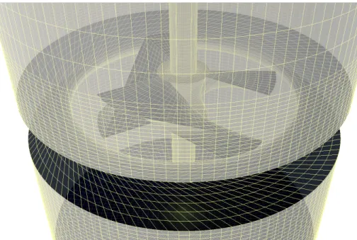
Starting with the equation of continuity for incompressible flow and using the Plateau border geometry, it is also possible to estimate the liquid fraction (ϕliq) in the foam using
Equation 2.5 [32, 163]. With this equation, Ξ is a dimensionless number which represents the relative position in foam height (X0).
∂ϕliq ∂t = ∂ ∂Ξ ( ϕ2liq− √ϕliq 2 ∂ϕliq ∂Ξ ) (2.5) Ξ = x x0 (2.6)
The model above is based on a unidimensional analysis. It’s a simple model that doesn’t include the surface theories, like those described previously. It helps a lot to develop an
understanding on how the liquid flows in the foam network. Better models have been developed since, but are much more complex and are necessitating an adequate introduction. Those more accurate models have been proposed by Hartland et al. and Pilon et al. Their models are described with few other in the review of Wang et al. [162]. Their review also includes foam drainage in the presence of solid particles, the kinetics of foam columns and few models of growth and collapse.
2.4.3
Apparent Viscosity
High shear conditions break the channels, which makes the foam more viscous and less plastic. When this is abstracted to apparent global viscosity, it can be said that the foam reacts as a shear thinning fluid. Foam ages and its liquid fraction change through time, and this has the consequence of changing its rheology. This implies that foam is considered as a thixotropic fluid.
A good model for the shear-thinning viscosity of the foam is the Herschel-Bulkley law [137](Equation 2.7). In this equation, τ is the shear stress, ˙γ is the strain and τ0 represents
the yield stress. The two parameters are k, the viscosity coefficient, and n is the power-law index.
τ ( ˙γ) = τ0+ k ˙γn (2.7)
Other authors have proposed other laws, often based on this equation. In his work on particles stabilized foam, Ozarmut proposed that the Herschel-Bulkley-Papanastasiou equation is better at low shear values [113]. The Herschel-Bulkley equation may be extended to a thixotropic equation by adding a structural decay parameter (λ) which depends on time [137].
τ (λ, ˙γ) = λ(τ0+ k ˙γn) (2.8)
The yield stress (τ0) is also difficult to determine. This is not a problem only for foam
2.5. FOAMING IN BIOREACTORS 19 [127, 137]. A literature review about the different methods used to evaluate the yield stress, using non-thixotropic flow, was written by Coussot [28].
The structure of foam does not uniformly wrap around surfaces. The term “wettability” is used to represent how much contact the surface has with the foam liquid phase. A surface with a low number of contacts, therefore, low “wettability”, will slip and transfer less energy to the foam. This effect, called wall slip, is to be accounted for a good characterization of foam behavior [38]. Most of the studies on foam’s apparent viscosity have used a serrated or rough surface to avoid this wall effect.
2.5
Foaming in Bioreactors
2.5.1
Consequences
Foam formation in bioreactors is a common phenomenon and is very often regarded as a nuisance [71, 151]. Its formation can cause many problems, some of them serious, while other ones are often disregarded. The obvious problem caused by foam generation is its volume, which can occupy a large fraction of the bioreactor working volume. An example of this is the volume problem during beer fermentations, which was studied by Kordialik [81], where the foam occupied nearly 25 to 33% of the vessel. Foam volume can be a significant problem but it would be ill-advised to consider this as the sole consequence of foaming. Foaming also has an impact on the behavior of the bioreactor, and it can impact not only the broth but also the microorganism involved.
The presence of foam can significantly affect bioreactor operations, leading either to a decrease in overall efficiency or to inhibition of a particular operation. The bioreactor design, choice of the impeller(s) and positioning of the baffles all aim at maximizing mixing and aeration and at minimizing the creation of dead zones. Those choices are usually performed using the physical properties of water such as viscosity and rheology. As seen in the previous section, foam behaves differently from water. This translates, in the end, into a drop-in bioreactor efficiency caused by lower mixing quality and higher energy consumption [151]. Foam presence can also hinder the probes by disturbing measurement, leading to false readings and analysis of the data. If the foam reaches the air filters, serious clogging may occur leading to pressure build-up and contamination of the culture [151]. Also, the
presence of foam in a bioreactor creates a barrier between the fermentation broth and the air in the headspace while the oxygen present inside the bubbles becomes rapidly consumed [151], thus, potentially leading to suboptimal aeration conditions which, in turn, might affect cellular metabolism more or less seriously depending on the microorganism or cellular system being used.
Foam has also an impact on the composition of the culture broth. The amphiphilic molecules found in the medium will have a better chance to find an energetic equilibrium at the interface between water and air [17]. By its nature, the foam provides a large number of interfaces, offering a preferential environment for amphiphilic molecules. Key molecules involved in the desired bioconversion can be trapped into the foam, making it inaccessible to the microorganism or absent in the final fraction recovered [81]. This phenomenon may deliberately be used to withdraw the target product from the overall broth [160]. The process, called fractionation, is used in many fields. This approach may either be used during the fermentation or post-fermentation [85]. Using the former strategy has the added benefit of withdrawing the foam from the bioreactor while possibly enhancing surfactant production whenever desired [85]. The foam may still have to be treated to minimize the volume of the receiving tank [85]. This type of fractionation seems to be of high interest in the microalgal field. It was seen as useful for withdrawing contaminants [148], for creating a favorable environment [67] and for recovering the microorganism following cultivation [3]. Foaming also influences the growth of microorganisms. Microorganisms may be trapped around a rising bubble. Entrapped microorganism are dragged to the surface of the fluid, this phenomenon can be used to isolate them in a fractionation. At this point, the bubble can burst or be added to the foam structure with the microorganisms attached. A lot of strain force is involved in a bursting bubble at a free surface. Chisti provided a good depiction of this phenomenon in his review of animal cell damages in sparged bioreactors [23]. While unicellular organisms are usually less affected, this event is destructive for animal cells [20, 23]. When the bubble is added to the existing foam, there is no immediate damage to the microorganism but the strain produced by the collapse of the bubbles and the draining of the lamellae can damage the microorganism [20, 23]. Overall, for the cultivation of animal cells, the damage caused by the air/liquid interface can compromise the fermentation. Often serum and a shear protectant, like Pluronic F-68, are added to the cellular suspension to reduce the damages caused by force at the air/liquid interface [114, 169]. They hinder the attachment of the cell on the rising bubble and strengthen the cell membrane [10, 20, 59]. Interestingly, the hydrophobic nature of shear protectants may also protect the cells by increasing the stability of the foam and lowering its draining [169].
2.5. FOAMING IN BIOREACTORS 21
Probes
Cooling / Heating Aeration / Sparger
Input
High flow rate Bubble-less aeration No aeration
Block air input/ouput
Hinder delivery/sampling or recirculation
Hinder or jam probes
pH effect on protein/organism Proteins, oil, amphiphilic mol.
Small bubbles Residuals on probes Reduce efficiency of air filter
Heat effect on proteins/organism Hot broth Cool broth Promote Mitigate Consequence Anti-foaming agent
Too much anti-foaming agent
Agitation
Strong mixing
High mechanical stress (stator or design) Gentle mixing Increase power input Foam breaker
Foam breaker in contact with broth
Broth / Sterilization
Caramelized sugars (Sterilization) Proteins, oil, amphiphilic mol. Surfactant-producing organism Reduced homogeneity
Draining amphiphilic Mol. Minimal/simple broth Hostile to organism Residuals on reactor walls
Figure 2.3 Foaming Control / Troubleshooting
2.5.2
Controlling Foam Production
Many events may occur during any fermentation process and foam can be produced via several mechanisms. It was said earlier that pure water could not maintain a foam. In any fermentation process, the foaming agent(s) may come from the broth [71] and from the microorganism. As the energy for foam formation may come from various sources, it is possible to control some of those sources to mitigate its production.
Presence in the broth or production by the microorganism of certain types of molecules will raise the foaminess of the system [81]. Molecules of an amphiphilic or hydrophobic nature will tend to be at the interfaces between the liquid and the gas and, thus, they will stabilize the bubble interfaces. The cellular membrane, which is formed of amphiphilic molecules, is a source of foaming agents. Hence, the high death rate of the microbial population should naturally promote foam formation. Also, to a lesser extent, the production of polymeric molecules, such as proteins, polysaccharides or fat can contribute even further to foam stability.
Knowledge of the microorganism phenotype can help to predict its propensity to generate foam. Any microorganism, which is known to produce, under appropriate conditions, foaming agents such as surfactants, is susceptible to promote foam formation, at least at
some time during the fermentation process. If the route for the production of the foaming agent is known, then, finding a way to mitigate its production could help to alleviate the foaming problem. An example of this approach was described by Koridalik-Bogacka and Ambroziak involving a hydrophobic polypeptide during beer fermentation [81]. They noted that less production of the hydrophobic polypeptide, thus less foaming, occurred when recycling yeast biomass from a prior fermentation.
It is also possible to evaluate the propensity of a broth to produce foam. In 1938, Bikerman proposed a property called “foaminess” to characterize this property [14, 128]. In his book, he described how to evaluate this property [15]. Even if the unit does not seem to be commonly used anymore, the techniques proposed by Bikerman are still being cited [1, 56, 71]. In practice, whenever possible, a simple solution for foaming mitigation could be to select a culture medium less prone to foaming. In addition, it is important to keep in mind that foaming agents can be produced at any step of a given fermentation process. An example of this could be the sterilization step, during which Maillard reactions occur, to produce foam enhancing molecules [61, 151]. Therefore, a well-designed sterilization process (for instance, slow depressurization) can reduce the foaming propensity of the medium in
comparison to other sterilization processes.
With the presence of foaming agents, the foam needs some energy to build its structure. Many operations inside the bioreactor can be a source of energy for foam formation. The obvious one comes from the oxygenation process, where bubbles are sparged inside the liquid phase of the bioreactor. A high gas flow rate combined with a sparger with larger holes will tend to produce even more foam [22, 151]. As a potential solution, one could think of using an alternative carrier for delivering oxygen. One way for supplying oxygen to the culture could be, for instance, using a membrane for the oxygen exchange. An even simpler solution could be to use anaerobic conditions or bubble-less reactors, whenever possible, for producing the same metabolite of interest. Another source of energy favoring foam formation is the intensive agitation conditions often associated with fermentation processes [62]. A bioreactor shares similarity with two chemical reactor models often used : the mixer and the bubble column. One approach to minimize this problem could involve optimization of the mixing conditions leading to a lower energy input. Finally, high temperature is known to reduce foam generation and this could offer a solution in several fermentation cases [121].
Foam fractionation [166], anaerobic fermentation [165] and bubble-less reactors [24, 29] solutions, to avoid foaming problems, have been applied to fermentations using Bacillus subtilis. Bacillus subtilis is an organism producing surfactin, a foam promoting agent.
2.6. CONTROLS USING ANTI-FOAMING AGENTS 23 Willenbacher et al. reviewed the literature on these strategies in his article about the anaerobic fermentation of Bacillus subtilis [165].
It is important to keep in mind that foam production is a desirable attribute in several fermentation processes. In those processes, foam can be used to increase the total surface area of the gas-liquid interfaces, improving the production of microorganisms or helping to control the content of the broth. This is particularly useful for the production of autotrophic organisms, like algae, which necessitate a large amount of light and CO2
[67]. In the foam-bed photobioreactor, used for this kind of fermentation, the foam is continuously regenerated to deliver fresh CO2 bubbles and avoid the accumulation of O2
[67]. This implies that the older foam has to be broken. It is usually done using mechanical foam breakers since the content in surfactants is usually high, which is desirable for foam-bed photobioreactors [67]. Numerous studies keep being published on various approaches aiming at increasing the quality of the foam and the reactor efficiency for this purpose. Among the various approaches used so far, one may mention the following ones : the production mechanism, the biosurfactant(s) itself/themselves, bioreactor design or the producing microorganism itself. Several examples of such studies may be found in recent publications by Janoska et al., dealing with microalgae production, where the authors’ goal was to improve the efficiency of a foam-bed photobioreactor [66, 67] together with selection of the best surfactant [68]. In addition, Vasquez et al. evaluated the potential of several different algae [152] for growth in such bioreactors.
2.6
Controls Using Anti-foaming Agents
2.6.1
Mechanism
It is not always possible to avoid the formation of foam during a fermentation process. Important or excessive foaming can arise rapidly, at any given time during the fermenta-tion, catching the operator by surprise irrespective of the production scale. That is why bioreactors are often equipped with one or more foam sensors coupled to an antifoam distribution system. Anti-foaming agents are chemicals that are added, either as needed or in a more or less planned way, to the broth to interact with the foaming agents in the gas-liquid interfaces. Such antifoams are usually organic or inorganic oils, particles or a
mixture of both. They can be used to prevent or mitigate excessive foam formation during the fermentation or to disturb or destroy the already formed foaming structures [117]. They all have characteristics making them interact with the gas-liquid interfaces. They show a few modes of action by which they can prevent the formation of foam or provoke its collapse.
Antifoam particles are known to slip inside the membrane and to force the two surfaces to fuse. This dewets the membrane and ultimately ruptures it [36]. To successfully bend the surfaces, the particles must be hydrophobic. Spherical particles with a contact angle over 90◦ will burst the membrane. For other shapes, the orientation of the particles will influence their actions. Their surfaces have to be at the right contact angle for dewetting the membrane. If placed along the surface, polyhedral shapes can stabilize the membrane instead of breaking it. The mechanism by which the particles act has been well studied. Both simulation and visual observations appear to confirm this mechanism.
A liquid antifoam, usually composed of oil, has many foam-breaking modes of action and these are still the subjects of numerous studies. Often, in the literature, they are split into two categories, either as slow/fast [35, 126] or as antifoam/defoamer [71, 117]. This observation is linked to the existence of many mechanisms by which anti-foaming agents operate. One of those mechanisms, which seems broadly acknowledged, occurs inside the liquid phase in a fully built foam. In such a case, as the oil forms it disturbs the surface, stops the flow and thereby makes the membrane collapse. The other potential scenarios, where the oil is interacting with the surface, still seem unclear. In one of the scenarios, theorized by Denkov [35], the oil would partially occupy the surface and force the dewetting of the membrane by increasing the disjoining forces. Both organic or inorganic compounds control foaming via the same mechanisms. Many of the organic compounds used to produce antifoams are already established food additives, however, they might be consumed by the targeted microorganism.
There are numerous articles and reviews about antifoam agents. One article from Garrett [50] addressed in detail the mechanisms presented above. Denkov offered a review of methods to characterize antifoam properties [35]. The review by Junker [71] contained an extensive list of chemicals antifoams together with their composition. Finally, the review from Karakashev and Grozdanova [73] covered the development of antifoams and methods to evaluate their efficiency.
2.6. CONTROLS USING ANTI-FOAMING AGENTS 25
2.6.2
Influence of Anti-foaming Agents on the Fermentation
Although chemical antifoams usually provide the most effective mechanism to control foaming in bioreactors, their presence in the broth has consequences. While mechanical methods doe not add any additional elements to the broth, chemical antifoams are adjuvants. Consequently, because of their composition or their general nature, they can generate diverse problems that can be critical for numerous fermentation processes.
Because the composition of antifoams is not always well known, it is usually wise to perform screening to identify the optimal antifoam for a particular fermentation. Antifoams can directly interact with some molecules present in the medium or with the microorganism itself. Such interactions are usually negative. Zhang et al. described a mechanism where the antifoam reduce the resilience of the cells and limits its exchange with the broth [121, 170]. Sometimes, the interaction with the antifoam can be positive, as observed by Routledge et al. for Pichia pastoris[126]. Tests proposed by Denkov [35] might be used for investigating a proper antifoam, like the one performed by Etoc et al. [46] for fermentations using Yarrowia lipolytica.
Even if the antifoams composition is uncertain, most are usually designed to interact with surfactants. This usually means that they will, themselves, be composed of surfactants. As a consequence, their use should be limited since their optimal efficiency holds only if they are used in the right concentration range [121, 151]. A high concentration can even promote foaming, and their presence at the gas-liquid interface may lead to numerous consequences. By altering the surface tension, anti-foaming influence the bubble distribution, making the bubble larger [2, 71, 117] while reducing their velocity. Those two phenomena reduce the exchange between the gas and the liquid, lowering the oxygen transfer rate, often identified as klA. In some publications it was observed that the addition of anti-foam
coupled with sparging damage animal cells [149, 170]. The presence of a chemical antifoam at the interface of rising bubbles makes them more prone to drag the microorganism to the surface [170] where they can be damaged by bubble bursting or trapped in the foam. The addition of shear protectant, like Pluronic F-68, seems to mitigate this mechanism [170]. Finally, chemical antifoams will often create difficulties in downstream processing [71, 116] or contaminate the final product. For example, they can clog filtration membranes or at least reduce their filtration rate [116], or be co-extracted with the product of interest. Finally, if the antifoam is used in a regulated industry it is important to make sure the chemical has been approved by a pertinent regulatory body.
![Figure 1.1 L’Univers rapproché avec ses vides et ses lamelles forme une structure très similaire à la mousse[120].](https://thumb-eu.123doks.com/thumbv2/123doknet/2991970.83347/26.918.245.661.105.497/figure-univers-rapproché-vides-lamelles-structure-similaire-mousse.webp)

![Figure 2.4 A) Paddle and C) needle foam breakers from Deshpande et al.[39] B) Cone foam breaker from Cook et al [? ] D) A simple bar foam breaker](https://thumb-eu.123doks.com/thumbv2/123doknet/2991970.83347/54.918.107.788.547.902/figure-paddle-needle-breakers-deshpande-breaker-simple-breaker.webp)