HAL Id: tel-02105785
https://tel.archives-ouvertes.fr/tel-02105785
Submitted on 21 Apr 2019
HAL is a multi-disciplinary open access archive for the deposit and dissemination of sci-entific research documents, whether they are pub-lished or not. The documents may come from teaching and research institutions in France or abroad, or from public or private research centers.
L’archive ouverte pluridisciplinaire HAL, est destinée au dépôt et à la diffusion de documents scientifiques de niveau recherche, publiés ou non, émanant des établissements d’enseignement et de recherche français ou étrangers, des laboratoires publics ou privés.
Cr VI -free conversion coatings
Perrine Tanguy
To cite this version:
Perrine Tanguy. Impact of the microstructure of ZnAlMg coatings for steel on the formation mech-anisms and performance of Cr VI -free conversion coatings. Inorganic chemistry. PSL research University, 2019. English. �tel-02105785�
Préparée à L’
École Nationale Supérieure de Chimie de Paris
Impact de la microstructure des revêtements ZnAlMg sur
les mécanismes de formation et la performance des
couches de conversion sans Cr
VI(Impact of the microstructure of ZnAlMg coatings for steel on
the formation mechanisms and performance of Cr
VI-free
conversion coatings)
Soutenue par
Perrine TANGUY
Le 30 janvier 2019
Ecole doctorale n° 388
École doctorale de Chimie
Physique et chimie
Analytique de Paris
SpécialitéChimie Physique
Composition du jury : Dominique, THIERRY Directeur de recherche,Institut de la Corrosion Rapporteur
Inger, ODNEVALL WALLINDER
Professeur, KTH Rapporteur
Herman, TERRYN
Professeur, VUB Examinateur
Kevin, OGLE
Professeur, IRCP – I2E Examinateur / Président du jury
Christian, ALLELY
Expert,
ArcelorMittal Maizières Research Examinateur
Polina, VOLOVITCH
Thèse de doctorat de
L’Université de recherche Paris Science & Lettres
PSL Research University
Ecole Nationale Supérieure de Chimie de Paris (ENSCP)
Impact of the microstructure of ZnAlMg coatings for steel
on the formation mechanisms and performance of Cr-free
conversion coatings
Présentée par
Perrine TANGUY
Pour obtenir le grade de
DOCTEUR DE L’UNIVERSITE DE RECHERCHE PARIS SCIENCE ET LETTRES Spécialité Chimie physique
Soutenue le 30 janvier 2019
Devant le jury composé de :
Dominique THIERRY Directeur de recherche, Institut de la Corrosion, Brest, France Rapporteur
Inger ODNEVALL Professeur, KTH, Stockholm, Suède Rapporteur
WALLINDER
Herman, TERRYN Professeur, VUB, Bruxelles, Belgique Examinateur
Kevin OGLE Professeur, IRCP – I2E, Chimie ParisTech, Paris, France Examinateur Christian ALLELY Expert, ArcelorMittal Research, Maizières-Les-Metz, France Examinateur Polina VOLOVITCH Maître de Conférences, CNRS, IRCP, Chimie ParisTech, Paris, France Directrice de thèse
Birth: 19/10/1992 in Lannion (22)
EDUCATION
2016 - 2019 Industrial PhD - Impact of the microstructure of ZnAlMg coatings for steel on the formation mechanisms and performance of Cr-free conversion coatings, ArcelorMittal MaizièresResearch, Institut de Recherche de Chimie Paris (I2E), PSL
Sept. 2014 Erasmus semester (6 months) – Teaching focused on Materials Science, Corrosion and Surfaces protection, KTH, Stockholm, Sweden
2012 - 2015 Chemical science and engineering graduate engineer, Chimie ParisTech (ENSCP)
2010 - 2012 DUT Mesures Physiques, speciality « Matériaux et Contrôles Physico-chimiques », option « Chimie organique », IUT de Lannion
WORK EXPERIENCES
2016 – 2019 Industrial PhD training - Comprehension of the conversion coatings mechanisms on multiphase ZnAlMg coated steel, ArcelorMittal Maizières Research, IRCP (I2E), PSL
o Understand Ti-based and phosphate-based conversion coatings formation mechanisms on multiphase ZnAlMg materials
o Investigate an alternative conversion coating application process, improving corrosion resistance of painted ZnAlMg and suitable for industrial process
o Determination of the corrosion mechanisms of Ti-based conversion coatings on painted ZnAlMg coated steels
2015 (6 months) Master thesis training – Applicability of SAF 2304 duplex stainless steel regarding its corrosion resistance in the GDI, Sandvik Materials Technology, Sandviken, Sweden
o Evaluation of the pitting corrosion resistance of SAF 2304 in contact with ethanol-based biofuel
o Determination of the pitting corrosion resistance of SAF 2304-containing an intermetallic phase formed during brazing
2014 (5 months) R&D training – Study of the twins created after tensile testing in a beta-metastable Ti-12Mo (%) alloy, Université Catholique de Louvain, Louvain La Neuve, Belgium
o Determination of the connection between the grain size, twin size and the distance between two consecutive twins in a beta-metastable Ti-12Mo (%) alloy.
o Evaluation of the twins reversion kinetics in the alloy after tensile testing using thermal treatment
: Advanced level C1 : Beginner level : Beginner level : Mother tongue (TOEIC: 990/990 - 2015)
SCIENTIFIC PRODUCTION
ArcelorMittal Project Reviews focused on “Knowledge Building” and “ZnAlMg for pre-painted applications” (2 reviews/year), 12 oral presentations (English), Maizières-Les-Metz (France) and Liège (Belgium).
Oral presentation at European Corrosion Congress 2018: P. Tanguy, C. Allély, D. Dragoe, P. Volovitch, “ZnAlMg microstructure effect on the composition and distribution of Ti-containing surface treatments”, Krakow, Poland, September 2018.
Poster at European Corrosion Congress 2017: P. Tanguy, C. Allély, P. Volovitch, D. Dragoe, V. Sefl, J. Stoulil, “Phosphate-based conversion coating on Zn-based multiphase substrate: Impact of activator”, Prague, Czech Republic, September 2017.
Poster at Doctoral school ED388 day (05/2016) and ArcelorMittal Learning week (06/2016): P. Tanguy, C. Allély, P. Volovitch “Formation and chemical stability of conversion coatings on ZnAlMg coated steels”.
ArcelorMittal confidential internal reports
RELEVANT SKILLS
2016 – 2019: Responsible of the chemicals storage for the research group Surface and Coatings, ArcelorMittal Maizières Research – Chemicals storage (acids, bases, solvents, CMR products), inventory listing, discharge of chemicals based on constant interactions with the environmental, safety and health department
Techniques knowledge, user level: XRD, SEM-FEG, EDS, XPS, AES, GD-OES, Raman spectroscopy, electrochemistry, SKP
Maintenant que s’achève ma thèse, je voudrais en profiter pour remercier les personnes qui m’ont aidé et ont contribué à cette aventure. Plus je prends le temps de me remémorer ces 3 années et plus la liste des personnes à remercier s’allonge, c’est pourquoi je vais tâcher d’être aussi exhaustive que possible.
Tout d’abord, je voudrais remercier Polina Volovitch, ma directrice de thèse, pour m’avoir recommandée pour cette thèse, m’avoir fait confiance et s’être autant investie dans mon apprentissage, directement mais aussi par l’intermédiaire des nombreuses rencontres avec d’autres chercheurs dont elle a été à l’origine. Je voudrais aussi remercier Christian Allély, mon encadrant chez ArcelorMittal Maizières Research pour sa supervision tout au long de ces 3 années, ses conseils et tout le temps qu’il m’aura consacré. Grâce à eux, ces 3 années ont été enrichissantes à plus d’un niveau.
Je voudrais aussi profiter de ces quelques mots pour remercier Michel Babbit, directeur du Centre de recherche Maizières Products et Jacques Petitjean, responsable du département Surfaces and Coatings (SurCoat) du centre Maizières Products, de m’avoir accordé ma chance et de m’avoir permis d’intégrer le département.
Il me semble impossible de ne pas remercier comme il se doit Diana Dragoe pour les nombreuses analyses XPS qu’elle a réalisée ainsi que pour toute son implication, sa disponibilité et sa patience qui nous ont grandement aidé à avancer tout au long de la thèse.
J’adresse mes sincères remerciements à Mélanie Vaudescal et Michel Lahaye du Placamat à Bordeaux pour leur collaboration sur la réalisation d’analyses nano-auger et le temps qu’ils auront pris à me faire découvrir cette technique.
Je voudrais aussi en profiter pour remercier particulièrement Anna Krasnova pour son aide dans la réalisation de certaines manipulations LEIM et sa disponibilité pour répondre à mes questions.
Dans le cadre de cette thèse, certaines caractérisations de surface ont été réalisées en collaboration avec l’équipe d’Analyses de surface du département SurCoat gérée par Marie-José Cornu et Sébastien Crémel et je voudrais les remercier pour leur collaboration tout au long de ces 3 ans et les résultats qu’ils nous ont permis de mettre en évidence sur certains sujets.
De manière générale, je remercie tous les membres du département SurCoat pour l’aide qu’ils m’auront apporté pendant ces 3 ans. J’ai beaucoup appris à leur contact, plus que je ne l’aurais moi-même soupçonné. J’ai évidemment une pensée toute particulière pour l’équipe
Comment ne pas remercier l’équipe I2E au grand complet pour tout leur soutien, leurs conseils et les nombreux services qu’ils m’auront rendus pendant cette thèse. Je voudrais en particulier remercier Thomas Sanchez, doctorant à l’I2E, Junsoo Han, post doc et Armelle Ringuedé, référente PSL de l’ED388 pour leur écoute, leur soutien sans faille et leurs précieux conseils, surtout pendant les derniers mois de la thèse. Une pensée spéciale pour Amandine Michot Mignucci pour les innombrables discussions que nous avons eues toutes les 2 et qui m’ont beaucoup fait grandir depuis que je l’ai rencontrée !
Je voudrais profiter de ces quelques lignes pour remercier Joël Marsal, directeur d’Allia-Tech. Les nombreuses discussions que j’ai eu avec lui ont toujours été très et il restera un très bon souvenir de mon expérience à Metz.
Quand je pense à tous les bons moments passés à Metz, ils sont quasi indissociables des personnes suivantes que je ne saurai remercier tant ils ont eu d’impact sur le souvenir que je garderai de ma vie à Metz : Cyril Nicard, Matthieu Siebentritt, Coralie Jung, Audrey Le Fichant, Vincent Feynerol, Benjamin Bauer, Aude Nadler, Céline Arrighi, Pauline Ronfart, Paula Vieira Salomao, Nicolas Tran et bien d’autres encore…merci pour tout ! 😊
Enfin, il y a des personnes qui m’ont soutenu d’aussi loin que je m’en souvienne et à qui je voudrais adresser mes remerciements les plus sincères et les plus profonds : mes parents Jean-Yves et Joëlle, ma sœur Aline, mon neveu Ronan ainsi que Nicolas Montesinos.
PhD thesis
Impact of the microstructure of ZnAlMg
coatings for steel on the formation
mechanisms and performance of Cr-free
Abstract
ZnAlMg multiphase sacrificial coatings on steel are regarded as a replacement of conventional hot dip galvanized steel in many applications including automotive and pre-painted market. Conversion coatings (CC) are applied to promote the paint adherence and improve the anticorrosion resistance of painted galvanized steels among which thick phosphate conversion coatings (PCC) and thin Ti-based coatings (TiCC) are used.
Preliminary outdoor corrosion testing has shown that, in presence of defects going down to the steel relevant for cosmetic corrosion evaluation, blisters can be developed on painted ZnAlMg coated steel with TiCC but not with PCC. Simultaneously, no blister was detected on painted monophase HDG sample treated with TiCC formulations.
One of the possible reasons for the blistering on ZnAlMg coated steel can be the presence of multiple phases (ZnAl-Zn2Mg-Zn) resulting in a galvanic coupling between phases during the
CC precipitation. CC are usually considered to precipitate according to a 2-step mechanism: (1) Dissolution of the underlying metal substrate in anodic areas associated with a pH increase from cathodic reaction in cathodic areas and (2) Precipitation of the conversion coating once a precipitation pH is reached. A multiphase substrate could, then, induce an inhomogeneous spatial distribution of cathodes and anodes and consequently modify the different rates of nucleation and growth of CC on these phases and the properties of the formed layer. The verification of the impact of the multiphase microstructure on the distribution of CC and is hence of great importance.
This PhD work had 2 main objectives:
- To identify the origins of the difference performance between PCC and TiCC-treated painted ZnAlMg materials during cosmetic corrosion testing, in particular, verify the impact of the ZnAlMg multiphase microstructure on the CCs composition, distribution and performance.
- To formulate a solution to overcome the impact of the multiphase ZnAlMg microstructure on the distribution of TiCC.
Model ZnAlMg coated steels and pure phases simulating ZnAlMg microstructure were characterized at different steps of the CC procedure. The similarity of Ti speciation in TiCC on all ZnAlMg phases was confirmed by XPS. Electron microscopy and nano-auger spectroscopy
and mapping however have shown that PCC grains form a homogeneous layer on all phases while the distribution of TiCC on ZnAlMg phases is heterogeneous, binary eutectic phases being better covered than monophase Zn dendrites. The heterogeneous CC distribution was consistent with the worsened blistering resistance of TiCC-treated ZnAlMg surfaces compared to PCC, verified by electrochemical measurements, LEIM and outdoor corrosion tests.
The origin of the homogeneous or heterogeneous distribution of CC on ZnAlMg was proposed to be related to the ratio between the ZnAlMg microstructure fineness and the conversion coating elements size. For PCC, the galvanic coupling inside the eutectic phases and between the micrometric-sized ZnAlMg phases has little influence on the distribution of micrometric phosphate grains. For nanometric TiCC, the galvanic coupling inside binary eutectic phases can be considered as the origin of different precipitation kinetics and CC distribution. This way, the galvanic coupling inside phases can be critical for CC-containing nanometric-sized elements. The hypothesis was confirmed by electrochemical measurements on pure phases simulating ZnAlMg microstructure and by comparing conversion coating precipitation on ZnAlMg materials and pure phases.
A solution was proposed to overcome the microstructure/CC elements size ratio issue, using a Cu or Fe cementation pretreatment prior to TiCC procedure. SEM, AES and XPS confirmed the deposition of metallic Cu or Fe during pretreatment resulting in a finer distribution of local cathodes/anodes on ZnAlMg surface as well as a resulting homogeneous distribution of the TiCC on ZnAlMg. LEIM experiments demonstrated the improved blistering resistance of ZnAlMg coated steel with the Cu pretreatment while scab test outdoor exposure confirmed the blistering corrosion resistance gain after 1 year of testing.
List of figures
Figure 1: Scheme of the Hot Dip Galvanizing process [10] ... 7
Figure 2: Scheme of the cross-section of ZnAlMg coated steel. Zn-Zn2Mg binary phase is composed of bright Zn lamellas and dark Zn2Mg ones while the ternary one includes Zn, Zn2Mg and an Al mesh. Zn-Al binary phase is composed of bright Zn areas and dark Al-rich ones (inspired by [12]) ... 8
Figure 3: Structure of a painted ZnAlMg coated steel for the pre-painted market ... 10
Figure 4: Schematic representation of anodic and cathodic reactions distribution during galvanic coupling ... 12
Figure 5: SEM photo of an electrogalvanized steel after 180 sec of phosphating in a ZnMnNi PCC bath [36] ... 15
Figure 6: Germination of PCC crystals on sites with adsorbed activator [37] ... 16
Figure 7 : Blistering around the down to steel defect after 22 months of natural exposure in a marine environment ... 19
Figure 8: Anodic delamination mechanism... 20
Figure 9: Cathodic delamination mechanism ... 21
Figure 10: Scheme of the cathodic blistering mechanism ... 23
Figure 11: Auger electron emission principle in AES ... 35
Figure 12: Principle of X-ray photoelectron spectroscopy [7] ... 36
Figure 13: Scheme of the Glow Discharge Optical Emission Spectroscopy principle ... 37
Figure 14: Local Electrochemical Impedance Spectroscopy (LEIS) explanatory diagram ... 38
Figure 15:Scheme of the SKP principle ... 39
Figure 16: Photo of ZnAlMg material after 24 months of outdoor exposure in marine environment ... 47
Figure 17: SEM images of cross sections of painted ZnAlMg with blisters ... 47
Figure 18: SKP mapping of painted and corroded ZnAlMg material with a down to steel scratch after 24 months of outdoor corrosion testing. The left figure shows optical image, the middle figure shows the topography and the right figure shows the values of Volta potential. ... 48
Figure 19: General view of painted HDG and ZnAlMg materials with an artificial defect down to steel after 72 h of anodic galvanostatic polarization in 1 wt. % NaCl solution with initial pH7. ... 49
Figure 20: SEM-EDS mapping of ZnAlMg material after 72 h of anodic galvanostatic polarization in 1 wt. % NaCl solution with initial pH7 ... 50
Figure 21: Anodic and cathodic polarization curves of pure phases relevant for ZnAlMg coating in 5 wt. % NaCl solution at a pH 7 and T=25 °C ... 51
Figure 22: Scheme of the degradation mechanism of painted ZnAlMg material from the down to steel scratch ... 52
Figure 23: Comparison of Ti 2p XPS spectra of: (a) as-received activator, (b) dissolved and solvent evaporated activator, (c) ZnAl, (d) Zn and (e) Zn2Mg ... 64
Figure 24: Ti 2p XPS spectra and respective curve-fittings of: (a) as-received activator, (b) dissolved and solvent evaporated activator, (c) Zn2Mg and (d) Zn ... 65
Figure 25: Evolution of open circuit potential of pure phases relevant for ZnAlMg coatings as a function of immersion time in PCC bath at 60 °C... 67
Figure 26: PCC grains density and morphology on ZnAlMg surfaces as a function of the use of a fresh activator, bath temperature and immersion time (as indicated) ... 69
Figure 27: PCC grains density and morphology on different materials as indicated after immersion in the PCC bath for 12 sec at 60 °C using: (1) no activation, (2) aged activation and (3) fresh activation (see text for detail) ... 70 Figure 28: Surface coverage evolution as a function of immersion time, ZnAlMg substrate composition, bath temperature and use of activator (as indicated) ... 71 Figure 29: Distribution of P, Ti, Mn and F by GD-OES profile on ZnAlMg after alkaline degreasing followed by immersion in TiCC bath at 60 °C for 30 sec ... 91 Figure 30: (a) SEM image of ZnAlMg coating (as indicated) after immersion in TiCC at 60 °C for 30 sec and EDS distribution of P, Ti, Mn and F on different phases and (b) SEM image of ZnAlMg and EDs mapping of Mg and F distribution after immersion in TiCC at 60 °C for 30 sec ... 93 Figure 31: AES profiles of different phases of ZnAlMg after immersion in TiCC bath at 60 °C for 30 sec after standard cleaning ... 94 Figure 32: SEM images of ZnAlMg surface after alkaline degreasing and immersion in TiCC bath at 60 °C for 30 sec : (a) before sputtering, (b) after theoretical 70 nm of depth sputtering and (c) after theoretical 300 nm of depth sputtering ... 95 Figure 33: Mean sputtering rates of untreated and polished (4000 SiC) Zn, ZnAl and Zn2Mg ... 96 Figure 34: XPS spectra windows of TiCC tracers on pure phases and multiphase ZnAlMg substrates as indicated after standard degreasing and immersion in the TiCC bath at 60 °C for 30 sec ... 98 Figure 35: Open Circuit Potentials (OCP) of pure phases in (a) TiCC bath pH 2.6, T=60 °C after 2 min of alkaline degreasing and (b) 5 wt. % Na2SO4 pH 2.6, T=60 °C ... 101
Figure 36: Potential evolution and current density of (a) Zn/Al coupling and (b) Zn/Zn2Mg coupling after respectively 30 min of immersion and 2 h of phase coupling in 5 wt. % Na2SO4 pH 2,6 at 25 °C ... 102 Figure 37: Predominant equilibrium species for 113 mM Zn2+ + 57 mM Al3+ + 57 mM Mg2+ +
112 mM PO43- + 66 mM Ti4+ + 88 mM Mn2+ + 420 mM F- using the Hydra-Medusa software
and associated database of equilibrium constants at 25 °C. Complexes used in the simulation include (a) for Zn species alone: ZnO (cr), Zn(OH)2, Zn(OH)3-, Zn(OH)42-, Zn4(OH)44+, ZnOH+,
Zn2(OH)62-, ZnOH3+; (b) for Al species alone: Al(OH)3, AlOOH, Al(OH)4-, AlOH2+,
Al13O4(OH)247+, Al2(OH)24+, Al3(OH)45+, AlOH2+; (c) for Mg species alone: MgO, Mg(OH)2,
MgOH+, Mg
4(OH)44+; (d) for Ti species alone: TiO2, TiO(OH)2, TiO(OH)3-, TiOOH+; (e) for
Mn species alone: Mn(OH)2, MnOH+, Mn(OH)3-, Mn(OH)42-, Mn2(OH)3+, Mn2OH3+; (f) for P
species alones: H3PO4, H2PO4-, HPO42-; (g) for F species alone: HF, H2F2, HF2-; (h) mixed
species: Zn3(PO4)2.4H2O, Mn3(PO4)2, MnHPO4, ZnF2, ZnF+, AlF2+, AlF3, AlF4-, AlF52-, AlF6
3-, MgAlO4, MgF2, MgF+, MnF+, MnF2, AlPO4, TiF62-... 103
Figure 38: Schematic diagram of the TiCC precipitation on ZnAlMg ... 105 Figure 39: Scheme of the TiCC precipitation mechanism on ZnAlMg ... 106 Figure 40: a) Measured OCP of different phases in Cu-modified alkaline cleaner and b) Cu mass gain measured on the Pt electrode as a function of the imposed potential in the Cu-modified alkaline degreasing bath at 55 °C ... 123 Figure 41: AES mapping of ZnAlMg surface after immersion in Cu alkaline cleaning at 55 °C for 2 min ... 124 Figure 42: AES deconvolution of Cu auger peak of ZnAlMg after Cu alkaline degreasing for 2 min at 55 °C ... 125
Figure 43: AES profile of ZnAlMg after immersion in TiCC bath at 60 °C for 30sec after Cu alkaline cleaning ... 126 Figure 44: a) Ti 2p, b) P 2s, c) Mn 2p and d) F 1s XPS window spectra of ZnAlMg after Cu2+
-modified alkaline degreasing and immersion in the TiCC bath at 60 °C for 30 sec ... 127 Figure 45: Gradient of the admittance modulus for ZnAlMg degreased with the standard cleaner: (a) after 2 h of immersion, (b) after 24 h of immersion and for ZnAlMg degreased with the Cu2+ modified cleaner: (c) after 2 h of immersion with alternating, (d) after 31 h of
immersion ... 129 Figure 46: Scheme of the TiCC precipitation mechanism on ZnAlMg after Cu2+-modified alkaline degreasing procedure ... 131 Figure 47: Scheme of the Ti-activator and PCC distributions explaining homogeneous precipitation ... 139 Figure 48: OCP of individual phases and current density measured for galvanic coupling of (a) Zn/Al and (b) Zn/Zn2Mg phases relevant for binary eutectics. The measurement was made after
30 min of immersion of uncoupled phases in 5 wt. % Na2SO4 solution with initial pH 2,6 at 25
°C (OCP) followed by 2 h of phase coupling (galvanic current values). ... 140 Figure 49: Schematic representation of formation of different CC species during reaction of Zn, ZnAl and Zn2Mg phases in TiCC bath ... 140 Figure 50: Schematic representation of inhomogeneous TiCC formation on the multiphase substrate ... 141 Figure 51: AES mapping of ZnAlMg surface after immersion in Cu alkaline cleaning at 55 °C for 2 min ... 142 Figure 52: Scheme of the TiCC precipitation mechanism on ZnAlMg after Cu2+-modified alkaline degreasing procedure ... 143 Figure 53: AES profile of ZnAlMg after immersion in TiCC bath at 60 °C for 30 sec after Cu alkaline cleaning ... 144 Figure 54: Schematic representation of a hot dip process for ZnAlMg coatings (1] ... 149 Figure 55: Electrochemical cell used for OCP measurements and galvanic couplings of pure phases (inspired by [2]) ... 152 Figure 56: Predominant equilibrium species for 113 mM Zn2+ + 57 mM Al3+ + 57 mM Mg2+ + 112 mM PO43- + 66 mM Ti4+ + 88 mM Mn2+ + 420 mM F- using the Hydra-Medusa software and associated database of equilibrium constants at 25 °C ... 157 Figure 57: XPS spectra of pure phases and ZnAlMg after standard degreasing and immersion in the TiCC ... 158 Figure 58: XPS spectra of ZnAlMg after Cu2+-modified alkaline degreasing and immersion in the Ti-based CC bath ... 161
List of tables
Table 1: List of the ZnAlMg coatings compositions commercialized by the main European and
Japanese steel companies [2]-[9] ... 6
Table 2: Standard electrochemical potential (V vs SHE) in 1M NaCl, 25 °C, 1 atm [65] ... 19
Table 3: Phases weight and molar composition and supplier ... 34
Table 4: Composition of pure phases and ZnAlMg ... 44
Table 5: Fraction of the surface (%) covered by Zn dendrites, binary phases Zn2Mg and Zn-Al, and ternary eutectic Zn-Al-Zn2Mg determined from the SEM images of top surface of coatings A, B and C and the typical linear size (µm) of phases ... 60
Table 6: Model phases relevant for ZnAlMg coatings: their chemical composition (from AAS), phase crystallography (from XRD) and microstructure (from SEM) as well as open circuit potential (OCP) in PCC bath at 60 °C after 12 sec and 100 sec of immersion ... 61
Table 7: Main components and their concentration in solutions used for the bication (Zn-Ni) phosphating procedure ... 61
Table 8: XPS analysis results of the atomic concentration of Ti measured on each phase (at. % Zn/ at. % Ti) ... 66
Table 9: Composition of ZnAlMg and pure phases relevant for ZnAlMg coating ... 86
Table 10: Main components and their concentration in solutions used for the TiCC procedure ... 87
Table 11: Elemental concentrations for the Hydra-Medusa software simulation of the precipitated species in TiCC... 88
Table 12: Atomic concentration of Ti measured on model phases (at. % Ti) ... 97
Table 13: Open circuit potential (OCP) of pure phases after 2 min in the degreasing bath at 55 °C ... 100
Table 14: Composition of ZnAlMg and pure phases corresponding to ZnAlMg ... 118
Table 15: Main components and their concentration in solutions used for the TiCC procedure ... 119
Table 16: XPS parameters used for Ti 2p peak deconvolution ... 153
Table 17: Binding energies of compounds with energies fitting pure phases and ZnAlMg peaks after standard degreasing and immersion in the TiCC bath ... 159
Table 18: Binding energies of compounds with positions fitting P 2s, Mn 2p and F 1s peaks on ZnAlMg after Cu2+-modified alkaline degreasing and immersion in the TiCC bath ... 162
Abbreviation list
ZnAlMg: ZM: Zinc-Aluminium-Magnesium coating for steel typically containing 1.5-11 wt. % of Al and 0.5-6 wt. % of Mg
HDG steel: Hot Deep Galvanized steel CC: Conversion Coating
REACH: Registration, Evaluation, Authorization and Restriction of Chemicals
CrVI CC: Hexavalent chromium conversion coating (use restricted by REACH legislation) TiCC: Ti-based conversion coating dedicated to the pre-painted market
PCC: Phosphate ZnNi-based conversion coating requiring a Ti-activation step prior to the conversion coating procedure
OC: Organic Coating
XPS: X-ray Photoelectron Spectroscopy AES: Auger Electron Spectroscopy TFA: Target Factor Analysis
PCA: Principal Component Analysis
FEG SEM: Field Emission Gun Scanning Electron Microscopy EDS: Energy Dispersive Spectroscopy
GD-OES: Glow Discharge Optical Emission Spectroscopy SKP-FM: Scanning Kelvin Probe Force Microscopy OCP: Open Circuit Potential
SHE: Standard Hydrogen Electrode SCE: Saturated Calomel Electrode DiP: Differential Interferometry Profiles EIS: Electrochemical Impedance Spectroscopy
LEIM: Local Electrochemical Impedance Spectroscopy CPD: Contact Potential Difference
TEM: Transmission Electron Microscopy wt. %: Weight Percent
at. %: Atomic Percent BZS: Basic Zinc Salts
Summary
Abstract ... 1 List of figures ... 1 List of tables ... 1 Abbreviation list ... 1 Introduction ... 1 Chapter 1: State of the art ... 5 1. Basic knowledge about ZnAlMg sacrificial coatings for steel ... 5 1.1. Development of ZnAlMg sacrificial coatings ... 5 1.2. ZnAlMg microstructure ... 6 1.2.1. ZnAlMg production by Hot Dip Galvanizing ... 6 1.2.2. ZnAlMg microstructure as a function of Al and Mg contents ... 7 1.3. Corrosion resistance of bare ZnAlMg compared to HDG ... 8 2. Painted ZnAlMg coated steels ... 10 2.1. Main layers present in painted ZnAlMg coated steel ... 10 2.2. Basics of conversion coatings procedure and formation mechanisms ... 11 3. Degradation mechanisms of painted ZnAlMg coated steels ... 18 3.1. Blistering corrosion of painted ZnAlMg coated steel with TiCC ... 18 3.2. General blistering degradation mechanisms ... 19 4. Interface weakness of multiphase substrates treated with CC ... 23 Conclusions of the State of the Art ... 24 Chapter 2: Materials and Methods ... 33 1. Materials ... 33 3. Conversion coating distribution determination ... 34 4. Conversion coating chemical composition evaluation ... 35 5. Conversion coating thickness measurement... 36 6. Electrochemical measurements ... 37 6.1. Global electrochemistry ... 37 6.2. Local electrochemical analyses: Scanning Kelvin Probe (SKP) and local Electrochemical Impedance Mapping (LEIM) ... 38 Chapter 3: Environmental degradation of painted ZnAlMg coated steel with Ti-based conversion coating ... 42 1. Introduction ... 42 2. Experimental ... 44 2.1. Materials ... 442.1.1. Painted ZnAlMg materials ... 44 2.1.2. Model phases ... 44 2.2. Outdoor natural exposure ... 45 2.3. Electrochemical measurements ... 45 2.4. Surface characterization ... 46 2.5. Scanning Kelvin Probe measurement ... 46 3. Results ... 46 3.1. Blisters morphology after field exposure ... 46 3.2. Connectivity between blisters after field exposure ... 48 3.3. Artificial blisters formed under anodic polarization ... 49 4. Discussion ... 51 5. Conclusion ... 52 Chapter 4: On the effect of multiphase microstructure of ZnAlMg substrate on the Ti-based activation and phosphate conversion coating distribution ... 57 1. Introduction ... 58 2. Experimental ... 59 2.1. Materials ... 59 2.1.1. Model ZnAlMg materials ... 59 2.1.2. Pure phases ... 60 2.2. Bication Zn-Ni phosphating solutions ... 61 2.2.1. Bication Zn-Ni phosphating procedure ... 62 2.3. Electrochemical measurements ... 62 2.4. Surface characterization ... 62 3. Results ... 63 3.1. Characterization of the activated surface before immersion in PCC bath ... 63 3.2. OCP evolution in PCC bath ... 67 3.3. Surface observations by SEM ... 68 3.3.1. PCC crystals morphology ... 68 3.3.2. Surface coverage evolution with time and T°C of PCC treatment ... 71 4. Discussion ... 72 4.1. Impact of the activator on the PCC growth mechanism and grain shape ... 72 4.2. Impact of the activator on the PCC distribution ... 73 5. Conclusion ... 75 Chapter 5: On the uneven distribution of Ti-based conversion coating on multiphase ZnAlMg coating ... 83 1. Introduction ... 84
2. Experimental ... 85 2.1. Materials ... 85 2.1.1. Model ZnAlMg materials ... 85 2.1.2. Model phases ... 86 2.2. TiCC solutions ... 87 2.3. TiCC procedure ... 87 2.3.1. Bication Zn-Ni phosphating procedure ... 87 2.3.2 Bath composition determination for Hydra-Medusa calculations ... 88 2.4. Electrochemical measurements ... 89 2.5. Surface characterization ... 89 3. Results ... 90 3.1. Depth profiles distribution of TiCC by GD-OES ... 90 3.1.1. Erosion profiles of TiCC on ZnAlMg ... 90 3.2. Surface distribution of TiCC by SEM-EDS ... 92 3.3. Local distribution of TiCC thickness on ZnAlMg phases by AES ... 94 3.3.1. Nano-AES profiles of TICC thickness on ZnAlMg phases ... 94 3.3.2. Erosion rates variation between Zn, ZnAl and Zn2Mg by GD-OES ... 96
3.4. TiCC chemical speciation and Ti concentration on pure phases with XPS ... 96 3.5. Electrochemical behavior of pure phases in degreasing and TiCC baths ... 100 4. Discussion ... 103 4.1. TiCC chemical composition on all ZnAlMg phases ... 103 4.2. Distribution of TiCC on ZnAlMg phases ... 105 5. Conclusion ... 107 Chapter 6: Improvement of TiCC homogeneity on multiphase ZnAlMg substrate using surface activation by Cu2+ modified alkaline degreasing ... 113
1. Introduction ... 115 2. Experimental ... 117 2.1. Materials ... 117 2.1.1. Model ZnAlMg materials ... 117 2.1.2. Pure phases ... 117 2.2. TiCC solutions ... 118 2.3. TiCC procedure ... 119 2.4. Local Electrochemical Impedance Spectroscopy and Mapping ... 119 2.5. Electrochemical measurements ... 121 2.6. Surface characterization ... 121
3. Results ... 122 3.1 Preliminary verification of Cu deposition from the modified cleaner by potentiostatic cathodic polarization ... 122 3.2 Cu distribution and chemical composition on ZnAlMg ... 123 3.3. TiCC thickness distribution on ZnAlMg phases measured by AES ... 126 3.4. TiCC chemical speciation on ZnAlMg after Cu2+-modified alkaline degreasing ... 127
3.5. Surface reactivity of epoxy coated samples by LEIM ... 128 4. Discussion ... 130 4.1. Cu precipitation mechanism on ZnAlMg phases ... 130 4.2. Effect of Cu cementation on TiCC precipitation mechanism ... 130 5. Conclusion ... 132 Conclusion and perspectives ... 138 1. Effect of microstructure on the formation of CC ... 138 2. Effect of microstructure on the degradation mechanism of painted ZnAlMg ... 144 3. Perspectives ... 146 Appendix 1 (Chapter 1) ... 149 Appendix 2 (Chapter 2) ... 150 Appendix 3 (Chapter 2) ... 151 Appendix 4 (Chapter 2) ... 152 Appendix 5 (Chapter 4) ... 153 Appendix 6 (Chapter 5) ... 157 Appendix 7 (Chapter 5) ... 158 Appendix 8 (Chapter 6) ... 161 Introduction ... 164
1
Introduction
ZnAlMg coatings are multiphase sacrificial coatings replacing monophase HDG Zn-0,2 Al wt. % in the automotive and pre-painted market. Thanks to the Al concentration increase and the addition of Mg, an improved corrosion resistance was allowed, reducing the sacrificial coating thickness as well as production costs of galvanic layers and increase of the lifetime of ZnAlMg coated steels.
To ensure the paint adherence on the ZnAlMg substrate, conversion coatings (CC) are applied prior to the different paint coatings. Due to the current European regulations, restrictions are in place about the use of phosphate and CrVI-based CC [1], [2]. Therefore, new
alternative CC are being developed for the last decade to replace the toxic CrVI-based CC
formulations. In the pre-painted market, Ti- based conversion coatings (TiCC) are regarded as a promising alternative.
However, in preliminary industrial tests made by ArcelorMittal Maizières Research on painted ZnAlMg coated steel dedicated to pre-painted market with TiCC, sometimes delamination and blisters were observed near the artificial scratches made down to the steel to simulate accidental defects that can occur in service life.
Unlike TiCC-treated ZnAlMg coated steel, ZnAlMg ones treated with phosphate-based CC (PCC) exhibit an enhanced blistering corrosion resistance. In addition, HDG coated steels treated with TiCC are not subject to blistering corrosion either. This way, the blistering issue results from a lack of adherence between the ZnAlMg coatings dedicated to the pre-painted market and the TiCC. One of the possible reasons of the latter can be an inhomogeneous TiCC distribution on the multiphase ZnAlMg substrate because of micro galvanic coupling between phases during the CC precipitation.
The identification of the origins of the different blistering resistance of painted TiCC and PCC-treated ZnAlMg, in particular, the impact of the microstructure on the CC distribution and performance and looking for a solution for improvement of TiCC performance were in the main scope of this PhD. The work was conducted in collaboration between ArcelorMittal Maizières Research and l’Institut de Recherche de Chimie Paris de l’Ecole Nationale Supérieure de Chimie de Paris. To achieve the objectives, several steps were necessary:
2 - The presence of preferential corrosion paths leading to the blistering on painted ZnAlMg
coated steel treated with TiCC was confirmed.
- The reasons of formation of homogeneous PCC on multiphase ZnAlMg substrate were understood.
- The inhomogeneity of TiCC on multiphase ZnAlMg coating obtained by a standard treatment procedure was confirmed and the role of substrate phase composition and spatial distribution of these phases in the formation mechanism of TiCC was understood. The inhomogeneous distribution of cathodic zones was shown to be the main reason for the inhomogeneity of TiCC distribution.
- Based on the elucidated mechanisms, a pretreatment was proposed improving the TiCC distribution on ZnAlMg phases by means of noble metal cementation and the efficiency of the proposed solution was demonstrated.
The manuscript is organized in four parts and includes seven chapters.
The first part includes this introduction which develops the context and the scientific questions that were answered during the PhD and the first chapter which summarizes the state of the art relevant to the work. The composition, microstructure and corrosion resistance of ZnAlMg sacrificial coatings are reviewed as well as the existing knowledge of the conversion coatings formation mechanisms for TiCC and PCC on Zn-based substrates and the degradation mechanisms of painted Zn-based coated steel, described in the literature, leading to delamination and blistering. The literature review enabled the selection of the pure phases simulating the phases contained in the ZnAlMg microstructure.
The second part, Materials and Methods, covers the materials and the electrochemical setup used in this work and introduces the main techniques used throughout the PhD, namely surface analysis techniques used to characterize the CC distribution and chemical composition and local electrochemical techniques for the detection of under paint corrosion such as delamination or blistering.
The third part presents the most important results obtained during this PhD. This part consists of 4 chapters formatted as publications prepared for submission to different journals.
Chapter 3 (“Comprehension of the degradation mechanisms TiCC-treated and painted ZnAlMg coated steels”) approaches the impact of ZnAlMg microstructure in the development and propagation of delamination and blisters. Corrosion mechanisms of painted ZnAlMg coated steel are discussed.
3 Chapter 4 (“On the effect of multiphase microstructure of ZnAlMg substrate on the Ti-based activation and phosphate conversion coating distribution”) focuses on the PCC distribution on ZnAlMg at different CC procedure steps and as a function of the activator freshness. The role of the Ti-based activator used prior to the phosphatation process in the formation of covering and crystalline grains on all ZnAlMg phases was exhibited. The inhomogeneity of the interaction of different ZnAlMg constituents with Ti-containing activator was shown and the importance of the micrometric grain size of PCC crystals for the formation of a homogeneous layer was demonstrated.
Chapter 5 (“Impact of phases in ZnAlMg coatings on the distribution of Ti-based conversion coatings”) develops the origin of the heterogeneous distribution of TiCC on ZnAlMg substrates. The electrochemical behavior of pure phases contained in the ZnAlMg microstructure confirmed the existence of a galvanic coupling inside phases and inhomogeneous TiCC distribution assessed by surface analysis techniques correlated with the expected from galvanic coupling distribution of cathodic zones. A schematic mechanism of TiCC formation on multiphase ZnAlMg substrate was proposed and the role of the ratio between the microstructure inhomogeneity scale and the CC element size was highlighted.
Chapter 6 (“Insight into the formation and degradation mechanisms of TiCC on multiphase ZnAlMg using Cu2+-modified alkaline degreasing baths”) presents the solution
selected to homogenize the TiCC distribution on ZnAlMg coatings, which is based on the cementation of metallic Cu during the degreasing step, allowing a finer cathodes/anodes distribution. The uniform chemical composition and the homogeneous thickness distribution of TiCC on ZnAlMg after the new pretreatment was confirmed by surface analysis techniques and better resistance in cosmetic corrosion test compared to a conventional procedure was confirmed by local electrochemical impedance mapping.
The last chapter (“Conclusions and perspectives”) summarizes the general conclusions brought by the thesis, their importance regarding the corrosion resistance of painted ZnAlMg coated steels and the perspectives of the study.
Several appendices give some additional details like design of specific experiments or technics, parameters used for XPS peaks deconvolution etc.
1 [1] European Chemicals Agency, « Substances restricted under REACH », ECHA, 2006.
[Online]. Available on: https://echa.europa.eu/substances-restricted-under-reach/-/dislist/details/0b0236e1807e2bc1. [Accessed on: 09/08/2018]
[2] European Chemicals Agency, “Nickel and its compounds”, ECHA, 2011. [Online]. Available on:
5
Chapter 1: State of the art
This chapter is a literature review about the structure and fabrication process of painted ZnAlMg coated steel. Additional research was carried out to compile the well-established degradation mechanisms leading to delamination and blistering on painted metallic substrate. This work was used as a basis for the methodology selected in the PhD. As the thesis will be presented in publication formatted chapters, it is worth noting that each chapter will include a short focused bibliographic introduction.
1. Basic knowledge about ZnAlMg sacrificial coatings for steel
1.1. Development of ZnAlMg sacrificial coatings
Historically, aluminium was the first alloying element to be incorporated to the galvanizing process at concentrations higher than the usual 0.2 wt. % Al used in continuous Hot Dip Galvanized steel (HDG). Notorious ZnAl sacrificial coatings in use nowadays are Galvalume ® (1972) and Galfan ® (1980) containing respectively 55 wt. % and 5 wt. % of Al [1]-[3]. It was later on noticed that adding up to 0.1 wt. % of Mg could significantly improve the corrosion resistance of Galfan ® in atmospheric and aqueous environments [4], leading to the commercialization of Super Zinc ZnAl4.5Mg0.1 (1985). This promising discovery opened the
way to the development of ZAM ® (1998) by Nisshin Steel, exhibiting 6 wt. % Al and 3 wt. % Mg [5]. Not only the corrosion resistance of the sacrificial coating was improved but the cathodic protection induced by the magnesium was also significantly increased. It led European steel companies but also Nippon Steel Corporation to manufacture new compositions of ZnAlMg from the early 2000s with various Al and Mg proportions [1]-[7]:
6
Table 1: List of the ZnAlMg coatings compositions commercialized by the main European and Japanese steel companies [2]-[9]
Company Commercial name
Commercialization
year wt.% Zn wt.% Al wt.% Mg Nisshin Steel ZAM 1998 91.0 6.0 3.0 Nippon Steel Corp. Super Dyma 2002 86.0 11.0 3.0 Tata Steel Magizinc 2007 97.0 1.5 1.5 Voestalpine Corrender 2007 96.0 2.0 2.0 Thyssen Krupp ZM Ecoprotect 2008 98.0 1.0 1.0 ArcelorMittal Magnelis 2010 93.3 3.7 3.0
1.2. ZnAlMg microstructure
The microstructure of materials is strongly influenced by their production process. ZnAlMg coatings are produced by continuous hot dip galvanizing.
1.2.1. ZnAlMg production by Hot Dip Galvanizing
Whether the steel is galvanized with the classic zinc-based coating (Zn-0.2 wt. % Al) or with a ZnAlMg layer, a similar Hot Dip Galvanizing process is used (Appendix 1). In the case of ZnAlMg coatings, the immersion bath is constituted of liquid zinc, aluminium and magnesium elements in a concentration defined for each commercial composition. In the framework of this PhD, ZnAlMg compositions with Al ranging between 1 and 11 wt. % and Mg up to 3 wt. % were studied, whether dedicated to the automobile or pre-painted market.
In the Figure 1 is displayed a scheme of the coating process. Both faces are coated with the same ZnAlMg coating thickness. The line speed is typically in the order of 100 m/min.
7
Figure 1: Scheme of the Hot Dip Galvanizing process [10]
First, the sheet surface must be free of contaminants and oxides to form a solid bonding between the zinc layer and the steel surface. To do so, an alkaline cleaning is performed to remove impurities and aluminium oxide. The steel sheet is heated in an annealing furnace to impart it the desired strength and formability. A protective atmosphere based on nitrogen and hydrogen (5 % H2 and 95 % N2) is used in the furnace to prevent the formation of an oxide layer on the
steel surface.
In order to make sure that the correct ZnAlMg coating thickness is applied on the surface, “gas knives” are used as they inject air on both sides of the steel sheet to remove ZnAlMg excess [11].
Parameters such as the bath composition, bath temperature and dipping time have to be controlled to get the targeted microstructure.
1.2.2. ZnAlMg microstructure as a function of Al and Mg contents
In ZnAlMg coatings microstructures, four solid phases can be found, namely a Zn-rich phase, Al-rich phase, Zn2Mg and Zn11Mg2. While Zn11Mg2 is rarely formed, other phases can form Zn
dendrites, binary eutectics Zn-Zn2Mg, binary eutectoid Al and/or the ternary eutectic
Zn-Al-Zn2Mg depending on the ZnAlMg coating composition (Figure 2). In the case of low
magnesium-alloyed compositions, the ternary eutectic phase is considered as a binary Zn-Al phase due to the very low Mg concentration measured.
The variation of the chemical composition of the phases compared to the equilibrium values was attributed to the rapid solidification of the ZnAlMg coating [12]. It is also responsible for the fine and complex microstructure of the coating.
8
Figure 2: Scheme of the cross-section of ZnAlMg coated steel. Zn-Zn2Mg binary phase is composed of
bright Zn lamellas and dark Zn2Mg ones while the ternary one includes Zn, Zn2Mg and an Al mesh.
Zn-Al binary phase is composed of bright Zn areas and dark Zn-Al-rich ones (inspired by [12])
Ratio of Al and Mg are usually adjusted depending on the desired mechanical, physico-chemical and other properties. In the pre-painted market, Al and Mg contents were selected to allow a high flexibility associated with a corrosion resistance twice better than HDG one [5], [9]. For low Mg-containing ZnAlMg compositions, the binary Zn-Zn2Mg phase is mainly
located at the surface of the coating, forming a continuous and surface located phase (first micron in depth), while Zn dendrites and the binary ZnAl phase form islands in the microstructure.
1.3. Corrosion resistance of bare ZnAlMg compared to HDG
It has been largely reported in the literature, through natural exposition and accelerated corrosion tests (VDA test, salt spray testing, scab test, Cl- -free test etc), that ZnAlMg coated
steels exhibit an enhanced corrosion resistance compared to Hot Dip Galvanized ones (HDG) in their un-painted state ([1], [3], [7], [8], [14]-[17] etc). However, different interpretations are proposed to explain this corrosion resistance gain.
9 The study of the corrosion resistance of ZnMg alloys compared to HDG coatings confirmed the beneficial effect of Mg alloying. It was explained that the formation of a dense layer of simonkolleite Zn5(OH)8Cl2·H2O, replacing poorly resistant ZnO on ZnMg surface, suppresses
the O2 reduction [18] which is the main reaction controlling the corrosion rate of the substrate
in neutral and/or slightly alkaline environment [19]. A long-lasting cathodic protection was attributed to the newly formed simonkolleite. In addition, the formation of Mg(OH)2 was
reported by Hosking et al. to limit the O2 reduction [20]. It was also proposed that the role of
Mg2+ ions was to buffer the pH around 10 by the formation of Mg(OH)
2 as well as to react with
carbonate ions, preventing CO32- from reacting with simonkolleite or other Zn-based products,
hence stabilizing them [14].
Considering the contribution of each alloying element in the improved corrosion resistance of ZnAlMg coatings compared to HDG ones, often the type of corrosion products formed on ZnAlMg was claimed to be at the origin of the corrosion resistance gain. Indeed, the formation of compact Layered Double Hydroxide (ZnAl-LDH) and simonkolleite corrosion products at the expense of poorly protective ZnO has been reported in many publications focusing on the characterization of the corrosion behavior of ZnAlMg compared to HDG coatings [1], [7], [8], [15], [17], [20]-[22].
Some other effects were also reported, for instance the released Mg2+ was proposed to induce
the formation of Mg-containing corrosion products but also to react with CO32- or SO42- to
stabilize corrosion products such as simonkolleite or zinc hydroxysulfate by preventing them from reacting with Zn to form soluble or low protective complexes [22]. The presence of Al was proposed to promote dense LDH formation at advanced stages of corrosion, as already reported in the literature [1], [7], [15], [21], while at initial stages of corrosion Al stays in insoluble form and selective dissolution of Zn and Mg occurs [22].
Thierry et al. studied the behavior of ZnAlMg coated steels in natural exposure and proposed that the dissolution of Al promotes the formation of different types of compact LDH corrosion products, lowering the corrosion rate of ZnAlMg [8]. The Mg was explained to induce a lower surface pH on cathodes and the formation of magnesium hydroxycarbonates and possibly magnesium hydroxychlorides on anodes.
Finally, Salgueiro et al. observed the formation of corrosion inhibiting Basic Zinc Salts (BZS) and LDH products on ZnAlMg surfaces under cathodic polarization in various electrolytes [16] which correlated with lower cathodic currents. The transformation of BZS into ZnO was
10 delayed by the presence of Mg2+ ions while Al3+ ones promoted the formation of stable LDH
even in very alkaline conditions. A non-oxidized Al skeleton was noted to keep corrosion products compactness.
The comparison of ZnAlMg coated and HDG coated steels has also demonstrated that the corrosion resistance gain is dependent on the exposure conditions and chloride content [8]. It was demonstrated that in environments involving a high time of wetness and high chloride load, the corrosion resistance gain of ZnAlMg over HDG was very relative.
In general terms, it has been commonly admitted that the formation of compact corrosion products acting as a barrier to the oxygen reduction on ZnAlMg surface is the source of the improved corrosion resistance of ZnAlMg coatings compared to HDG coatings.
Hence, it enabled reducing by a factor of two the ZnAlMg coating thickness/weight while keeping an equivalent corrosion resistance as HDG coatings [5], [9].
2. Painted ZnAlMg coated steels
2.1. Main layers present in painted ZnAlMg coated steel
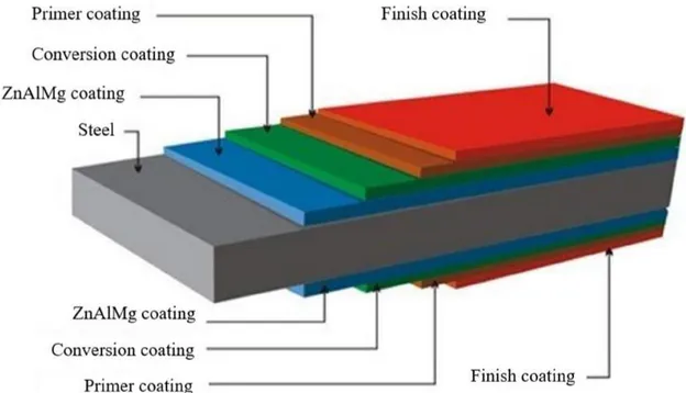
A typical structure of painted ZnAlMg coated steels is illustrated in Figure 3 (layers thickness is not representative).
11 As mentioned earlier (section 1.2.1.), the ZnAlMg, applied by hot dip galvanizing process, enables the formation of a sacrificial coating with a thickness of 10 µm [5], [9]. To ensure the paint adherence on the ZnAlMg coating and provide corrosion protection to the painted ZnAlMg coated steel, conversion coatings (CC) are applied prior to the paint. They are inorganic thin insoluble oxide layers with thicknesses ranging from 10 nm up to 1 µm depending on the type of conversion coating applied on the metal surface [24], [25]. Different layers of paint can be applied on the CC depending on the targeted physical, mechanical properties, corrosion resistance etc of the painted ZnAlMg coated steel among which a primer and a top coat. First, the primer, directly in contact with the CC, is applied to provide corrosion protection and ensure a good adhesion of the paint by wetting the surface. A top coat is commonly applied as the finish coating, promoting the cosmetic appearance and surface resistance required for the system. Depending on the exposure conditions, they might also exhibit UV, bacteria, condensation resistance properties etc. The paint thickness is comprised between 5 and 30 µm for the primer and 15 and 200 µm for the finishing coat.
Depending on the targeted application, both CC and paint layers can be deposited using different processes. Indeed, in the automotive sector, the immersion procedure is in use [25] while in the pre-painted market, coatings are applied by coil coating [10].
For painted Zn-based coated steel, the overall paint adherence and corrosion resistance is ensured by CC. They have been extensively studied in the literature and their formation mechanisms on metal substrates is of electrochemical nature. They act as a physical and insoluble barrier limiting the O2 reduction on the metal surface, thus the corrosion rate [23],
[24], [26]. Although various types of CC exist depending on the underlying metal substrate and application process, a common deposition mechanism pattern was observed for all of them.
2.2. Basics of conversion coatings procedure and formation mechanisms
Before the CC procedure, the galvanized steel surface is usually prepared by an alkaline degreasing to remove oil, grease and metallic oxides on the top of the sample. It is particularly efficient for aluminium and zinc oxides dissolution as they are very soluble in alkaline media [27]. The alkaline degreasing solution (10 < pH < 13) is composed of a base associated to surfactants and cleaning agents [28].
After the pretreatment, the conversion coating procedure is usually considered as a two-step mechanism. The first step is the establishment of cathodic and anodic sites on the surface,
12 responsible for pH increase and Zn-ions release (Fig. 4). The metal dissolution corresponds to the anodic reaction while the reduction of hydrogen ions or the reduction of oxygen constitutes the cathodic reaction. The interaction between the conversion coating electrolyte and the substrate defines cathodic and anodic areas on the surface.
Figure 4: Schematic representation of anodic and cathodic reactions distribution during galvanic coupling
The pH increase acts as the trigger for the CC precipitation. Once a threshold pH is reached, the precipitation of the CC takes place, forming insoluble oxide layers of various thickness and isolating the underlying metal from the atmosphere. In function of the chemical composition of
13 the bath and the formed layer, different types of conversion coatings are known for galvanized steels. They will be discussed in the following sections.
2.2.1. Chromiun (VI) CC
Historically, chromium (VI) CC has been the most widespread conversion coating as it provides excellent corrosion protection and adhesion for polymeric-based paint [23]. The CC versatility enables using it over a wide range of metal substrates such as steel [23], Zn-based [28], [29], Al-based [31]-[33], Mg-based [34] alloys etc. Their composition is considered as the simplest since the oxidant is strong enough to lead to the metal dissolution and the conversion coating formation. CrVI CC are aqueous solutions of chromic acid H
2CrO4, chromium salts (sodium
chromate Na2CrO4, potassium chromate K2CrO4 or dichromate), hydrofluoric acid HF and
phosphoric acid H3PO4 [23]. The 2-step deposition mechanism of CrVI on HDG substrate can
be described as follows:
- Anodic dissolution at anodes:
Zn → Zn + 2e (1-1) CrVI ions are very strong oxidants. Considering their concentration in the solution, the oxygen
reduction and the hydrogen evolution are negligible. The reduction of CrVI, present either as
CrO42- or Cr2O72- [27], [33], occurs from pH = 2 [23]:
- Oxidant reduction at cathodes from pH = 2:
CrO + 5H + 3e → Cr(OH) + H O (1-2) Or
Cr O + 8H + 6e ↔ Cr O . H O + 3H O (1-3)
The resulting CC thickness is about 100 nm [23]. In addition, CrVI CC are known for exhibiting
a “self-healing” property in case the coating presents a defect down to the steel [23], [31], [32]. The self-healing ability of the conversion coating is built during the redox reaction occurring on the surface [32]. Indeed, as the CC is forming, CrVI ions get trapped inside the conversion
layer. When a defect is created, the release of CrVI that diffuse to the defect and react with the
metal substrate can form a new CC in the defect, hence provide corrosion protection.
Although CrVI CC proved their efficiency over the years, they represent a non-negligible
carcinogenic, mutagenic and toxic threat [35], [36]. Legislations designed by the REACH organization (Registration, Evaluation, Authorization and Restriction of Chemicals) have
14 required the development, and subsequent experimentation of various alternative CrVI-free CC
formulations.
2.2.2. Phosphate CC
Phosphate CC (PCC) are among the most used CC for a wide range of substrates such as iron, steel, Zn, Al and Mg-based alloys [37]-[42]. The trication phosphating is the most common chemical conversion process in the automotive industry. PCC coatings exhibit thicknesses in the micrometric range. The PCC composition consists of a phosphate source, Zn cations and accelerators (NO3-, NO2- etc.) [37], [43]. Accelerators such as chlorates, nitrites or
nitrates…also serve to prevent the reduction of H+ into hydrogen gas which disturbs the
phosphating process. Additional cations (Ni2+, Mn2+ etc.) can be added to the basic formulation.
While both, Mn2+ and Ni2+, are considered to decrease the grain size of the precipitated
phosphates, Ni2+ is expected to act as a cathode and accelerate the surface reaction during the
phosphating process but seal the pores of the PCC, limiting the anodic undermining [44]-[47]. For HDG, the PCC formation mechanism is represented by the following reactions were proposed [37], [38], [48], [49]:
- Anodic dissolution:
Zn → Zn + 2e (1-4) - Cathodic reduction leading to pH increase:
NO + 2H + 2e → NO + H O (1-5) Or
NO + 8H + 6e → NH + H O (1-6) - PCC precipitation in pH range from 4.7 to 8.5 [49]):
2PO + 3Zn + nH O → Zn (PO ) . nH O (Hopeite) (1-7) In the case of a tri-cation phosphating, the reaction becomes:
(3 − x − y)Zn2++ xMn2++ yNi2++ 2PO43−+ zH2O ↔ Zn3−x−yMnxNiy(PO4)2. zH2O
15 A phosphate surface exhibit the presence of PCC grains as shown in the Figure 5
Figure 5: SEM photo of an electrogalvanized steel after 180 sec of phosphating in a ZnMnNi PCC bath [36]
To ensure a homogeneous distribution of the conversion coating on the surface, activators such as sodium titanium phosphates Na4TiO(PO4)2 are commonly used as an activation step
immediately before phosphating. The deposition mechanism of the activator on the surface is described as follows 1) particles of titanium phosphates adsorb on the surface of the metal substrate due to their low solubility and help the germination of the phosphate crystals. Then, 2) a cationic exchange between sodium and metal cations occurs that leads to the adsorption of the salt MexTiO(PO4)2 on the surface [50].
16
Figure 6: Germination of PCC crystals on sites with adsorbed activator [37]
The information gathered throughout the literature reported a similar behavior of the activator. Van Roy et al. demonstrated that zinc phosphate crystals preferentially nucleate on adsorbed activator particles during the PCC procedure [51]. According to Ogle et al., the activation step helps increasing the number of phosphate crystal per unit area while decreasing the crystal size, overall coating weight and minimize reaction time [37]. This interpretation was confirmed by Erbe et al. who compared the zinc phosphate distribution with and without activation step on an aluminium-silicon coated steel [52]. Indeed, they observed that the crystal size was reduced when an activation step was included in the process and that the size distribution of the crystals was more homogeneous.
Phosphating is a reliable conversion coating which does not rely on the use of CrVI. However,
17 is also considered as a carcinogenic element but is not yet under the blow of a ban by the legislation. Alternatives are currently under development to be able to produce a conversion coating avoiding the use of CrVI and Ni.
2.2.3. Titanium and zirconium-(titanium) based conversion coatings
Titanium and zirconium-(titanium) based CC are now considered as one of the most promising alternatives to CrVI CC and PCC. These new formulations are not harmful for the health and
the environment but are more complex than CrVI CC and PCC. Conversion coatings baths
contain Ti and/or Zr as hexafluorotitanic acid (or hexafluorozirconic acid) H2TiF6/H2ZrF6,
phosphoric acid H3PO4, manganese phosphate Mn3(PO4)2, an organic phase and water [54]. It
is generally assumed that thin Zr-based CC (ZrCC) and TiCC, follow a similar precipitation mechanism as they both exhibit a partial orbital-d filling (Ti: [Ar] 3d² 4s²; Zr: [Kr] 4d² 5s²). The coating thickness associated to TiCC and ZrCC is at nanometric scale [50]. Because of the low thickness of the TiCC/ZrCC, the chemistry of the formed CC is not fully understood yet. It has been largely admitted that the precipitation of TiCC and ZrCC leads to the formation of stable and insoluble oxides, TiO2 and ZrO2. However, Wilson et al. studied the formation mechanisms
of TiCC on HDG coated steel and demonstrated the formation of a mixed manganese/titanium phosphate Ti/Mn(PO4)x, zinc phosphates Zn3(PO4)2 and zinc hydroxides Zn(OH)2 using
FT-IRRAS and X-ray Photoelectron Spectroscopy (XPS) [55].
Similarly, as for CrVI-CC and PCC, the precipitation of TiCC on HDG is considered as a
multi-step process consisting of 1) the metal substrate dissolution accompanied by local alkalization from cathodic reactions leading to 2) the CC precipitation as titanium oxide (1-9 and 1-10) at pH = 2.5 – 8.5 [24], [56].
- Anodic dissolution:
Zn → Zn + 2e (1-9) - Cathodic reduction leading to pH increase:
O + 4H + 4e → 2H O (1-10)
2H + 2e → H (1-11)
- TiCC precipitation:
18 The conversion coating is reported to be composed of two different phases. The first one corresponds to the different phosphates, oxides and hydroxides while the second one refers to the organic coating flocculating with titanium oxide. The conversion of the second phase starts at pH=7 when the organic phase flocculates with titanium oxide before leading to a precipitation at pH=9 [50].
Globally, despite the various CC formulations, a common precipitation mechanism pattern exists between them. It is based on a 2-step mechanism: 1) the dissolution of the metal substrate at anodes accompanied by the oxidant reduction leading to a pH increase at cathodes and 2) the CC precipitation from a threshold pH. It makes the replacement of harmful CC such as CrVI and
PCC easier. However, an evaluation of the corrosion resistance of CC is necessary to ensure their ability to replace CrVI-CC or PCC for the desired application.
3. Degradation mechanisms of painted ZnAlMg coated steels
3.1. Blistering corrosion of painted ZnAlMg coated steel with TiCC
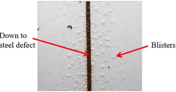
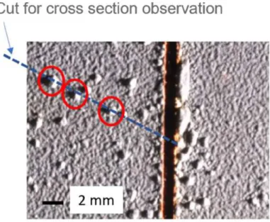
Through natural exposure testing in an environment with a corrosivity index of C3 (for pure Zn) or C5 (for steel) according to the ISO 9223 standard, the corrosion resistance of painted ZnAlMg coated steel treated with TiCC was evaluated. After 22 months of natural exposure in a marine environment, blisters can be observed in case of a down to steel defect (Figure 7). In case of exposure in a semi-tropical environment, blisters can appear after 8 months of testing. In the framework of this PhD, blisters are associated with circled local paint decohesion which are distant from the down to steel defect and not directly with it, unlike delamination.
19
Figure 7 : Blistering around the down to steel defect after 22 months of natural exposure in a marine environment
The blistering corrosion has already been discussed in the literature [57]-[59] but no study reported the case of blistering occurring only if the defect goes down to the steel.
3.2. General blistering degradation mechanisms
Different mechanisms have been described in the literature to explain the coating disbondment on metallic substrate ([60]-[64]) Mechanisms taking place near the defect will participate in the delamination development while degradation mechanisms occurring away from the defect will enable blisters growth.
3.2.1. Anodic and cathodic delamination Anodic delamination
Anodic delamination is observed when a ZnAlMg coated steel, painted or not, exhibits a down to steel scratch. Indeed, when an electrolyte gets in contact with ZnAlMg and the steel, a galvanic coupling is defined between the two metals. It will lead to the preferential dissolution of the zinc-based coating as its own galvanic potential is lower than the steel one:
Table 2: Standard electrochemical potential (V vs. SHE) in 1M NaCl, 25 °C, 1 atm [65]
Electrochemical potential standard (V vs. SHE) Zn ↔ Zn2+ + 2e- -0.76 ± 0.01
20 The contact between the two metals will induce an increase of the dissolution rate of zinc and a decrease of the iron one compared to the dissolution rate they have when they are not in contact with each other. This way, the zinc gets sacrificially consumed to protect the steel. The dissolution of the sacrificial coating creates paint delamination as shown in Figure 8.
Figure 8: Anodic delamination mechanism
In a neutral environment, the corrosion rate is defined by the cathodic reaction which is the oxygen reduction. The corrosion mechanism is the following:
- Anodic dissolution of the metal:
Me → Me + ne (1-13) - Oxygen reduction at the cathode:
1
2O + H O + 2e → 2OH
(1-14) The anodic delamination is also characteristic of a strong interface between the ZnAlMg and the paint. Indeed, the conversion coating is not affected by the dissolution and is adherent on the paint when delamination starts [60]-[61]. After paint removal, the coating is supposed to be located on the paint side.
For painted ZnAlMg steel with a down to steel defect, the anodic delamination takes place close to the defect, where the electrolyte is in contact with the steel and creates the galvanic coupling. Simultaneously, at the delamination front, the cathodic delamination is predominant.
21 The paint delamination results from a local alkalization of the media leading to the destruction of the interface between the polymer and the metal hence an electrolyte inflow. At the front delamination, the metal potential is more cathodic than closer to the defect. A galvanic coupling is created between the metal substrate located at the delamination front and the metal closer to the defect. In the confined zone, the oxygen concentration brought in by the electrolytic inflow is lower than near the scratch. In addition, corrosion products form a natural barrier that slows chlorides and hydroxyl ions from reaching the delamination front. At the delamination front, the pH evolution is governed by buffering reactions, diffusion rates of reactants to the front and hydroxyl ions, oxygen reduction rate and volume of liquid trapped under the paint [60]-[61]. The initiated oxydo-reduction reactions are described here after (Figure 9):
- Anodic dissolution close to the defect (“open area”):
Me → Me + ne (1-15) - Oxygen reduction at the delamination front (“confined zone”):
1
2O + H O + 2e → 2OH
(1-16)
Figure 9: Cathodic delamination mechanism
Although a system exhibiting a scratch down to the steel will facilitate the incorporation of water through the scratch, water can also flow in through the paint which acts as a semi-permeable membrane [60]-[61] hence also leading to blistering.
![Figure 6: Germination of PCC crystals on sites with adsorbed activator [37]](https://thumb-eu.123doks.com/thumbv2/123doknet/7763721.255549/42.892.221.659.106.729/figure-germination-pcc-crystals-sites-adsorbed-activator.webp)