• Aucun résultat trouvé

Contribution to the optimization of Unequal Area Rectangular Facility Layout Problem

N/A
N/A
Protected

Academic year: 2021

Partager "Contribution to the optimization of Unequal Area Rectangular Facility Layout Problem"

Copied!
167
0
0

Texte intégral

(1)

HAL Id: tel-01716010

https://hal.archives-ouvertes.fr/tel-01716010v2

Submitted on 28 Oct 2020

HAL is a multi-disciplinary open access archive for the deposit and dissemination of sci-entific research documents, whether they are pub-lished or not. The documents may come from teaching and research institutions in France or abroad, or from public or private research centers.

L’archive ouverte pluridisciplinaire HAL, est destinée au dépôt et à la diffusion de documents scientifiques de niveau recherche, publiés ou non, émanant des établissements d’enseignement et de recherche français ou étrangers, des laboratoires publics ou privés.

Contribution to the optimization of Unequal Area

Rectangular Facility Layout Problem

Ranjan Kumar Hasda

To cite this version:

Ranjan Kumar Hasda. Contribution to the optimization of Unequal Area Rectangular Facility Layout Problem. Mechanical engineering [physics.class-ph]. École centrale de Nantes, 2017. English. �NNT : 2017ECDN0026�. �tel-01716010v2�

(2)
(3)

i

CONTRIBUTION TO THE OPTIMIZATION OF UNEQUAL AREA RECTANGULAR FACILITY LAYOUT PROBLEM

_______________________ A Thesis

Presented to

École Doctorale SPIGA « Sciences Pour l'Ingénieur, Géosciences, Architecture » LS2N « Laboratoire des Sciences du Numérique de Nantes »

Ecole Centrale de Nantes, Nantes, France ______________________

In Partial Fulfillment

of the Requirements for the Degree Doctorate

_______________________ by

Ranjan Kumar Hasda 2017

© Ranjan Kumar Hasda 2017

Keywords: Facility Layout, Continuous Optimization, Discrete Optimization, Greedy Method, Hybrid Construction and Improvement Approach

(4)
(5)

iii

COMMITTEE MEMBERS Président :

Directeur de thèse : Fouad Bennis, Doctorate Professeur de génie mécanique

Ecole Centrale de Nantes, Nantes Rapporteur : Damien Chablat, Doctorate Professor of Robotics

Ecole des Mines de Nantes

Rapporteur : Laurent Pino, Doctorate Maître de conférences

(6)

ABSTRACT

A facility layout design is one of the most commonly faced problems in the manufacturing sectors. The problem is mixed-integer in nature and usually an NP-hard problem, which makes it difficult to solve using classical optimization techniques, which are better for local search. To overcome these limitations, two algorithms have been proposed for solving static facility layout problems with the unequal size compartments. The objective function of the problems considered is nonlinear in which the sum of the material handling cost has been minimized.

In the first approach, a hybrid constructive and improvement model has been proposed where an advanced bottom-left fill technique was used as constructive approach. The constructive model proposed also acts as a local search method based on greedy algorithm. For improvement approach a hybrid genetic algorithm has been proposed, where the crossover and mutation operator are specially designed to handle the solution representation which itself is used as constructive model.

In the second approach, a combined local and global search model was proposed where a rotation operator was used to avoid mixed-integer formulation of the problem. Use of rotation operator has also reduced the number of variables significantly. Apart from the conventional evolutionary operators this model has also used exchange and rotation operators.

The performances of both model are tested over a previously solved problem selected from the literature. The evaluation of the results shows that the performances of the proposed models are better than many existing algorithms and has the potential for field applications.

(7)
(8)

ACKNOWLEDGMENTS

I would like to express my sincere gratitude and appreciation to my supervisor, Professor Fouad Bennis, for his guidance, encouragement, constructive critiques, enthusiasm and patience throughout this research. He has been a great mentor and guide to me. This thesis would not have been possible without him.

I am also grateful to visiting Professor Rajib Bhattacharjya from IIT Guwahati, for his valuable comments, insights and feedback at LS2N. I benefited greatly from his both professional and less professional discussions, giving me both inspiration and encouragement. I am also thankful to Ramakrishnan Ramachandran, Post. Doctorate and Prabandh Chakraborty, Masters, for their valuable suggestions during my thesis work.

I am also greatly indebted to generous financial support from India4EU II, Erasmus Mundus Action 2 project funded by the European Commission and Institut de Recherche en Communications et Cybernétique de Nantes, Ecole Centrale de Nantes

Above all, I wish to thank my mother Kanaka Hasda, my brother Santosh Kumar Hasda and my sister Sushma Hasda for their constant moral support, encouragement and love and my friends Ritanjali Sethy, Deep Seth and Ranjan Jha and others for their constant support and help in all my endeavors.

(9)

1 TABLE OF CONTENTS ABSTRACT ... I ACKNOWLEDGMENTS ... III TABLE OF CONTENTS ... 1 LIST OF TABLES ... 5 LIST OF FIGURES ... 7 CHAPTER 1: INTRODUCTION ... 11 1.1. Motivation ... 11

1.2. Facility Layout Design ... 12

1.3. Problem Statement ... 12

1.4. Thesis Objectives ... 13

1.5. Organization of the Thesis ... 13

1.6. Conclusions ... 14

CHAPTER 2: LITERATURE REVIEW ... 15

2.1. Introduction ... 15 2.2. Packing Problem ... 16 2.2.1. Bin Packing ... 19 2.2.2. Strip Packing ... 22 2.2.3. Component Packing ... 24 2.3. Layout Problem ... 26

(10)

2.3.1. Architectural Layout ... 28

2.3.2. Facility Layout ... 29

2.3.3. VLSI Circuit Layout ... 31

2.4. Mathematical Representation ... 34

2.4.1. Quadratic Assignment Problem ... 36

2.4.2. Mixed Integer Problem ... 38

2.4.3. Quadratic Set-Covering Problem ... 40

2.4.4. Sequence Pair Representation ... 42

2.4.5. Two-Dimensional Bin-Packing Problem ... 43

2.4.6. Graph-Theoretic Formulations ... 44

2.5. Conclusions ... 45

CHAPTER 3: SOLVING LAYOUT PROBLEMS ... 47

3.1. Introduction ... 47

3.2. Design Optimisation ... 48

3.3. Formulation of an optimization problem ... 49

3.4. Evolutionary Algorithm ... 50

3.4.1. Genetic Algorithm ... 52

3.4.2. Discussion ... 54

3.5. Solving Layout Problems ... 55

3.5.1. Exact approaches ... 55

3.5.2. Heuristic and Metaheuristics ... 57

3.5.3. Hybrid Approaches ... 75

3.5.4. Interactive Approaches ... 78

3.6. Critical Review ... 81

(11)

3

CHAPTER 4: HYBRID FACILITY GROWTH HEURISTIC ... 83

4.1. Introduction ... 83

4.2. Methodology ... 84

4.3. Initial Facility Growth Heuristic ... 86

4.3.1. Block’s Representation ... 86

4.3.2. Solution Representation ... 88

4.3.3. Local Search Algorithm ... 89

4.3.4. Stepwise Material Handling Cost Calculation ... 91

4.3.5. Placement of Incoming Blocks ... 92

4.4. Genetic Algorithm ... 94

4.5. Modified Genetic Algorithm ... 94

4.5.1. Tournament Selection ... 95

4.5.2. Crossover Operator ... 96

4.5.3. Mutation Operator ... 98

4.6. Results and Discussion ... 99

4.6.1. 8 Blocks problem ... 100

4.6.2. 11 Blocks problem ... 102

4.6.3. 20 Blocks problem ... 104

4.7. General Discussion of the Proposed Model ... 107

4.8. Conclusion ... 109

CHAPTER 5: COMBINED GLOBAL AND LOCAL SEARCH ... 111

5.1. Iterative Search Importance ... 111

5.2. Methodology ... 116

5.2.1. Population Based Local Search Model ... 117

(12)

5.2.3. Exchange ... 121

5.2.4. Rotation ... 123

5.2.5. Interchange ... 125

5.2.6. Elitism ... 126

5.3. Results and Discussion ... 127

5.3.1. Problem 1: 8 Blocks Problem ... 127

5.3.2. Problem 2: 11 Blocks Problem ... 129

5.3.3. Problem 3: 20 Blocks Problem ... 130

5.4. General Discussion about the Proposed Method ... 131

5.5. Conclusion ... 134

CHAPTER 6: CONCLUDING REMARKS AND FUTURE WORK ... 135

6.1. Conclusions ... 135

6.2. Future Work ... 137

(13)

5

LIST OF TABLES

Table 4.1. An example of solution representation for the proposed hybrid algorithm. ... 89

Table 4.2. Material flow from each department and the length and width of each department for 8 blocks. ... 100

Table 4.3. Solution of Problem 1 ... 100

Table 4.4. Results for 8 blocks problem for Type I and II representation ... 102

Table 4.5. Material flow from each department and the length and width of each department for 11 blocks. ... 102

Table 4.6. Results for 11 blocks problem for Type I representation ... 104

Table 4.7. Results for 11 blocks problem for Type II representation ... 104

Table 4.8. Material flow from each department and the length and width of each department for 20 blocks. ... 105

Table 4.9. Length and width of each department of 20 blocks ... 106

Table 4.10. Results for 20 block problem with type I representation ... 106

Table 4.11. Results for 20 block problem with type II representation ... 107

Table 4.12. Comparison of the solutions obtained by our proposed hybrid method with other continuous methods ... 109

Table 4.13. Percentage improvement in percentage ... 109

(14)

Table 5.2: Case b: Negative weight between two department. ... 113

Table 5.3: Case c: A department with negative weightage for all other department. ... 113

Table 5.4: Case d: Negative weightage on some departments. ... 114

Table 5.5: Case e: Negative weightage for all departments ... 114

Table 5.6. Solution of Problem 1 ... 128

Table 5.7. Solution of Problem 2 ... 129

Table 5.8. Solution of problem 3 ... 131 Table 5.9. Comparison of the solutions obtained by our proposed method with other method. 133

(15)

7

LIST OF FIGURES

Figure 2.1. Examples of Packing Problems. ... 18

Figure 2.2. Bin Packing. ... 20

Figure 2.3. Strip Packing. ... 23

Figure 2.4. 2D Layout Problems. ... 28

Figure 2.5. Examples of different problems of placement of modules in VLSI [EGE03]. ... 33

Figure 2.6. Arrangement of 9 rectangles with IPN notation 123VV456VV789VVHH. ... 33

Figure 2.7. Example of departments in Quadratic Set Covering Problem. ... 40

Figure 2.8. Layout space in Quadratic Set Covering Problem. ... 41

Figure 3.1. Working principles of genetic algorithm. ... 53

Figure 3.2. A Bottom-Left Method [JAK96]. ... 59

Figure 3.3. Left out empty space in between blocks in bottom-left heuristic. ... 59

Figure 3.4. An improved Bottom-Left Method [LIU99]. ... 60

Figure 3.5. Storing placement location for one implementation of bottom-left-fill. ... 61

Figure 3.6. A comparison of the Bottom-Left and Bottom-left Fill placement heuristics when adding a rectangle. ... 62

Figure 3.7. 2D representation with circles for a polygon. ... 78

Figure 3.8. 2D representation of a shelter with virtual components. ... 80

(16)

Figure 4.2. Type I possible positions of the incoming facility to a parent facility ... 87

Figure 4.3. Type II possible positions of the incoming facility to a parent facility ... 88

Figure 4.4. Stepwise placement of blocks according to minimum Material Handling Cost. ... 91

Figure 4.5. Layout for different chromosome with same facility order but different parameter value. ... 93

Figure 4.6. Tournament Selection. ... 96

Figure 4.7. Crossover Operator ... 97

Figure 4.8. Mutation Operator ... 99

Figure 4.9. Optimal Solution for Problem 1 ... 101

Figure 4.10. Optimal Solution for Problem 2 ... 104

Figure 4.11. Optimal Solution for Problem 3 ... 106

Figure 5.1. Components representation in a layout for different possibilities. ... 115

Figure 5.2. A facility layout problem with two blocks of different size. ... 117

Figure 5.3. Flowchart shows the modified genetic algorithms based search model. ... 120

Figure 5.4. Population showing locational and dimensional variables. ... 121

Figure 5.5. Chromosome of locational variable. (b) Chromosome of dimensional variable. .... 121

Figure 5.6. (a) A chromosome before exchange operation. (b) A chromosome after exchange operation. ... 122

Figure 5.7. (a) Two parents before exchange operation. (b) Two parents after exchange operation. ... 123

Figure 5.8. (a) A chromosome before applying rotation operation. (b) A chromosome after applying rotation operation. ... 124

(17)

9

Figure 5.9. (a) A solution before applying rotation operator. (b) A solution after applying rotation operator. ... 125 Figure 5.10. (a) A chromosome before applying interchange operation. (b) A chromosome after applying interchange operation. ... 126 Figure 5.11. (a) A solution before applying interchange operation. (b) A solution after applying interchange operation. ... 126 Figure 5.12. Elitism Operator ... 127 Figure 5.13. (a) An optimal solution of problem 1. (b) An alternate optimal solution of problem 1. ... 128 Figure 5.14. (a) An optimal solution of problem 2. (b) An alternate optimal solution of problem 2

... 130 Figure 5.15. (a) An optimal solution of problem 3. (b) An alternate optimal solution of problem 3. ... 131

(18)
(19)

11

CHAPTER 1: INTRODUCTION

1.1. Motivation

The continuous evolution of worldly-wise and extensive applications such as Buildings, Circuits and Human-Machine Interfaces design has given rise to a strong appeal in formulating and automating layout design algorithms and guidelines. Many areas of Operations Research and Decision Sciences has been motivated from these applications and built up a significant research in formalizing layout design algorithms, preferences, and fitness measures [DOW02; YOU03; TOM10]). However, despite being an active research area, layout design field is still unclearly defined. The available research mostly provides design algorithms and guidelines in a very rigid and simple framework, without a detailed methodology for applying [TOM10]. The usefulness of such immense scattered knowledge is further limited by cognitive limitations of users. To address some imperfection of the existing research, this dissertation presents a new research and solution methodology for undertaking the Layout Design problem. It approaches some important issues faced in layout design by providing means to comprise complex, subjective, and evolving preferences into the design process and fast generation and manipulation of superior layout alternatives.

(20)

1.2. Facility Layout Design

In Facility Layout Design, usually the location of the facilities in the manufacturing plants are determined with the aim of finding the best possible arrangement while fulfilling certain criteria or objectives with constraints.

The Facility Layout Design also plays a key role in attaining production efficiency as it directly affects the manufacturing cost, lead times and productivity [KOU92]. The facilities with best possible layout contribute to the overall efficiency of the operations that reduces about 20-50% of the final operating cost [TOM10]. There are different types of facility layout problems that has been detailed in the next chapter. Some researchers also have classified facility layout designs, for example [KUS87]; [CAG98]; [DRI07] and [KUL07].

1.3. Problem Statement

The objective of the research is to develop a generic framework for the layout design. However, we tend towards two-dimensional static unequal area facility problem for analysis and illustration purpose. The formulation of the two-dimensional Layout problem is very difficult which can be easily and largely adapted with certain rules and preferences giving a generic approach to the layout design problems [GAR81]; [DYC90]; [LIG00] and [BUR04]. In the rectangular facility layout problem, the rectangular departments are located in a rectangular layout space in an orthogonal manner. The layout problem has been formulated differently by researchers and some have been in listed in the Section 2.4. The investigation carried out is conditional and are limited to the following.

1. The research focus is on unequal area rectangular fixed dimension facility layout problem where the total facility area is restricted within the layout space.

(21)

13

2. The areas of the rectangular facilities are known in advance.

3. The problems under consideration are taken from the previous literature and facility size varies from 8-20.

4. The research is focused on the constructive and iterative technique using an evolutionary algorithm for solving the facility layout problem.

1.4. Thesis Objectives The aim and objective of the thesis is to:

1. To provide a literature review of the facility layout problem alongside discovering the most adequate unexplored proposal for research.

2. To provide the methodologies for solving facility layout problems.

3. To formulate and evaluate a constructive and iterative approach for solving the facility layout problem with improved performance.

4. To improve the solution of layout problem by inclusion of the local search technique with the global technique which helps in finding the global minima.


1.5. Organization of the Thesis The thesis is organized in 6 parts which is described as follows: CHAPTER 1:. Provides motivation and reasoning for this thesis.

CHAPTER 2: Provide a literature review of the placement problem and tools with their significance for the research.

CHAPTER 3: Provide a general study of the several solving techniques necessary for solving the UA-FLP.

(22)

CHAPTER 4: Proposes a constructive approach combined with an evolutionary algorithm with implementation on a UA-FLP problem from the literature. CHAPTER 5: Proposes a combined local iterative search and global search evolutionary

algorithm for solving UA-FLP.

CHAPTER 6: Concludes the thesis with explanation of the results and insights achieved from the research in addition with the future lines of research.

1.6. Conclusions

In this chapter, the description and introduction of the facility layout problem with its significance have been described. We presented a review of the existing research on FLPs and approaches to solve the FLPs. We also presented the study of the approaches to solve the FLPs helped in discovering the adequate proposal for research. We also indicated the importance of both constructive and iterative approach of solving the facility layout problem. Moreover, the research is expected to develop algorithms for solving the FLPs. On review of first algorithm, it improves the results obtained from the literature but has certain limitations to its approach. In the second algorithm, the limitation faced by the previous algorithm was tackled in an attempt make a generic approach.

(23)

15

CHAPTER 2:

LITERATURE REVIEW

2.1. Introduction

In this thesis, a wide range of disciplines has been added such as the layout design, ergonomics, operation research, computer-aided designs, expert systems, intelligent systems, production research etc. Therefore, a comprehensive review of all the literature, concepts, efforts are beyond the scope of this thesis. In general, an overview of the literature and basic concepts are provided from the facility layout problems. In particular, the unequal area facility layout problems are emphasized. Furthermore, some of the limitations of the existing layout problems has been outlined from which a promising research methodologies is proposed to overcome these limitations.

(24)

2.2. Packing Problem

The primary objective in a packing problem is to pack all the components without overlap into a least possible packing space for maximising the total space utilization. Some of the industrial applications of packing problems are space utilization in sheet metals, paper, plastic, strip packing and textile industries. Certain applications also need additional constraints and assumptions for packing of components inside the packing space. For example, in the optimization of rectangular bin packing problems the following conditions are also satisfied.

- The edges of the components and the bin should be parallel to each other. - The orientation of the components is fixed and cannot be rotated.

- No overlaps between the components are allowed. - Minimum numbers of bins are to be allocated. - All components should be placed inside the bin.

The main objective of a packing problem is the compactness. Normally, the system compactness is designed with respect to some geometrical constraints such as non-overlap and some other functions. On the other hand, several difficulties are faced in modelling specific constraints and formulation of the objective. Moreover, Different packing types such as bin packing, strip packing have dissimilar constraints and objectives.

The dimension of a packing problem also influences the difficulty in solving the optimization problem. The two-dimensional packing problems are relatively easier to optimize compared to the three-dimensional packing problems. To begin with, survey related to packing problems, consolidation of researches relevant to modelling and solution of layout problems in two and three dimensions was carried out by Dowsland et.al, 1992 [DOW92]. They have also consolidated the research carried out on exact and heuristic solution approaches. They have

(25)

17

reported several works on packing problems such as two and three-dimensional rectangular packing, non-rectangular packing, pallet loading and strip packing. Moreover, they have recommended that there is still plenty of scope for the researcher into packing problems in spite of the extent of existing methodology.

The three-dimensional problems are more complicated than the two-dimensional problems due to additional constraints, and more variables in the objective and constraint functions. Moreover, special mathematical solvers are required to solve the intricate problem. A typical three-dimensional packing problem with cuboidal blocks is as shown in Figure 2.1(b). To optimize the 3D packing problem, Szykman and Cagan, 1997 [SZY97] developed a simulated annealing based computational algorithm. They have used spatial constraints in the optimization model that are characteristics of a 3D packing problem. These constraints are flexible enough that allows the user to restrict translation or rotation of the components with respect to the global origin or relative to other components. Similarly, an extended pattern search algorithm [YIN00]

was used for efficient 3D component packing optimization. Extended pattern search allows the algorithm to find the global optimal solution in a 3D layout while bypassing the several local minimal solutions.

(26)
(27)

19

that the computational time is reduced drastically when compared to the computational time found in related literatures. Albano, 1997 [ALB77] solved a problem where the main objective is to cut shapes from a given sheet of material so that, minimum wastage is attained. He proposed an algorithm that automatically generates tentative solutions and then conversational display unit to make interactive improvements.

Bin and strip packing are the two common packing problems available in the literatures. In several industrial applications, it has been seen that bin and strip packing problems have similarity in their algorithmic approaches in obtaining the optimal solution. Conversely, they do differ a lot based on application. Strip packing involves cutting a single standardized unit (a roll of cloth) into multiple strips with minimum waste or obtaining the required items by using the minimum roll length in a textile or paper industry. In warehousing (packing) contexts, the standardized stock units are commonly considered as rectangular items and the objective is to pack all the rectangular items into a large sized rectangular bins or shelves. The resulting optimization problem is called as bin packing problem [LOD02a]. In section below, we will see in detail and literatures relevant to different bin packing method and strip packing problems.

2.2.1. Bin Packing

Bin packing problem aims at packing a maximum number of items into a certain quantity of bins such that constraints value (say total weight, volumes) does not exceed some maximum value [HOP99]. There exists a large contribution in this area. To solve specific bin packing problems, we focus on some well-known algorithms such as Best-Fit algorithm and First-Fit algorithm [DÓS14]. According to Best-Fit algorithm, a new bin is opened if the item does not fit into currently opened bin. This method ensures that each bin is completely filled with Best-Fit

(28)
(29)

21

overcome this drawback, the Bottom-Left algorithm has been modified as Bottom-Left-Fill placement algorithm. This algorithm allows placing each item at the lowest available position of the object. In order to achieve high quality layouts in an industrial placement problem, the Bottom-Left-Fill heuristic algorithm is recommended over a sufficient number of iterations.

A relaxation placement algorithm proposed by Jacquenot et al., 2009 [JAC09] handles the 2D multi-objective placement problem with complex geometry components. It is based on the hybridization of a genetic algorithm and a separation algorithm. Moreover, it can solve a placement problem with several types of placement constraints. They have claimed that high quality solutions will be obtained when appropriate parameters are used in genetic algorithms. They have also studied the influence of initial population and parameters of genetic algorithm on optimization results.

To solve a simple two-dimensional rectangle-packing problem, a two-level search algorithm was developed by Chen and Huang, 2007 [CHE07]. In this algorithm, the blocks are placed in a container one by one and corner-occupying action was followed to place each rectangle in a position. This action touches two items without overlapping the other already packed blocks. Initially, a simple A0 algorithm selects and packs one rectangle according to the highest degree first rule at every iteration of packing. Then in the second level, the benefit Candidate Corner-Occupying Action (CCOA) was evaluated by A0 to a more global level. Similarly, A1 packing algorithm developed by same authors produces high-density solutions within short running times.

Similarly, Jain and Gea, 1998 [JAI98] presented a method based on Genetic Algorithm (GA) that can be used for solving 2D problems with convex, concave and complex shaped objects, including objects with holes. A concept named two-dimensional genetic chromosome

(30)

was introduced. The total packing space was made into a finite number of cells so that it maps into the 2D genetic algorithm chromosome. In order to reduce the creation of faulty generations, the mutation and crossover operators were modified.

Three-Dimensional problem consists of allocating a given set of three-dimensional rectangular items to the three-dimensional identical finite bins (minimum number of bins) without overlapping [LOD02b]. Literatures pertaining to three-dimensional packing problem generally use the extended algorithm used in case of 2D problem. However, Martello et al., 2000

[MAR00] compared the conventional accurate and heuristic approaches to solve the

three-dimensional packing problems. Industrial applications such as, e.g., container and pallet loading, material packaging design commonly faces three-dimensional packing problems. Zhu et al.,2012

[ZHU12] used finite spheres to approximate the components in a cube container and optimized

the problem using finite circle method to get a solution.

2.2.2. Strip Packing

Strip packing problem is a kind of packing problem where a set of n components are packed in an open-ended bin with a fixed width and infinite height [CHU82; BER87]. In rectangular strip packing problem, the condition of packing remains same as the rectangular bin packing problem i.e. the components should not overlap with each other and a set should take a minimum packing space as possible. The only difference between the strip packing and two-dimensional bin packing is that, in strip packing the minimisation packing space is done only for one bin whereas in bin packing the minimisation is done for a finite number of bins. Strip packing problem is generally a NP-hard where all items have the same height is equivalent to the one-dimensional bin packing [GAR79; MAR03]. Some of the application of 2D Strip packing

(31)
(32)

functions and three mutation operators. The initial solution in a tree search improvement procedure proposed by them determined by the best solution obtained by the evolutionary algorithm.

Similarly, Bekrar and Kacem, 2009 [BEK09] solved a two-dimensional strip-packing problem with the guillotine constraint. They proposed a dichotomic algorithm that uses lower bound, an upper bound, and a feasibility test algorithm. Computational results obtained show that the dichotomic algorithm, using the new bounds gives good results compared to existing methods.

2.2.3. Component Packing

Component packing problems are a common problem in many engineering applications such as layout of automobile engine compartments and design of mechanical or electromechanical assemblies. Component packing problems are also known as component layout problems as there are certain relationship or constraints within each component but it is categorized as packing problem as the general objective is to achieve high degree of compactness. Component packing tasks are characterized by three problem-independent objectives: achieving high packing density (due to trends in product miniaturization), fitting components into a specified container, satisfying spatial constraints on component placements. Packing Optimization of components is a key and common problem in several engineering applications such as layout design of an automobile engine parts assembly [MIA08], space shuttle cargo bay, and pallet loading and ship container packing [SZY95]. Component layout problem deals with three major objectives:

(33)

25

- Optimal placement of components in a structured container - Satisfying the constraints on placement of components

Miao et al., 2008 [MIA08], has presented a strategy to optimize several components in a military truck like three axles, engine, transmission system, tank, carburettor, drums etc. using Non-Dominated Sorting Genetic Algorithm-II (NSGA-II). The problem has three main objectives, which relate to maintainability, survivability, and rollover propensity. The knowledge associated with the problem allowed them to construct a parameterized model, on which a multi-objective optimization was performed. The intersections between components are evaluated using the CAO ACIS 1 software. The positioning of the components is taken as real variables whereas the orientation as discrete. The simulated binary crossover operator and a polynomial mutation operator were used in the genetic algorithm. A two-bit binary encoding is used to represent the four 90 degree rotations of a component around an axis. As noted by Grignon and Fadel, 2004 [GRI04], the use of relative benchmarks reduces the search space and limits the number of possible intersections between components.

He et al., 2012 optimized a thermal engine layout to improve the compactness in a compact

layout [HE12]. Moreover, compact system optimization resulted in optimal position of the external bladder is at the tail while the optimal of the front bellows is at the nose. The Optimum layout decreased the moving distance of the mechanical moving object by 24%. Moreover, they have found that buoyant centre is placed at an optimal position near accumulator and the middle bellows. It has been reported that the overall moving distance is reduced to 43%.

In 1998, Cagan et al., 1998 [CAG98] have presented and illustrated an approach to 3D component placement problem through various test cases and applications. For optimal layouts, they have used the simulated annealing search to efficiently approximate intersections of

(34)

complex geometric shapes. Models of components were arranged in a hierarchical fashion. The optimization algorithm developed has the capability to optimize any irregular shaped geometry inside an irregular shaped packing space with multiple objectives and constraints. The researchers claimed that algorithm was successful in variety of practical industrial layout problems. Faster solving capability of layout problems with better up front prediction of performance, layout costs and production feasibility are the implication of this technique.

A simulated annealing based optimization approach proposed by Szykman and Cagan, 1995 was generally used for solving the three-dimensional packing problem [SZY95]. However, they have further extended their simulated annealing based algorithm for solving three-dimensional layout problems as well [SZY97]. The new algorithm developed by them deals with all three objectives required as discussed above for the optimization of component layout problem. The inclusion of spatial constraints for the components allows the designer to carryout various activities like setting desired component proximity, restrict translation motion, rotation of components with respect to global origin and so on.

2.3. Layout Problem

Layout problems are generally found in different of manufacturing systems and have a great impact on the performance of the system [DRI07]. Location of facilities i.e. machines and departments are the typical known layout problems in an Industry. Layout problems are complex and known to be generally Non-Deterministic Polynomial-time (NP) hard. In a typical 3D layout of a workspace, a rectilinear shape, but not necessarily a convex polygon represents each cabinet. As the cabinet heights are same, the 3D problem can be simplified and conceptualized to a two-dimensional layout problem. Characteristics of a layout problem are well defined by the

(35)

27

compactness, dimensions, objectives and associated constraints. This subsection will consolidate famous literatures on different characteristics of a layout problem.

The departments or workstations are considered to be of rectangular shapes by many researchers, though others have assumed that the departments or workstations have irregular-shaped areas [BUK14]. They provided a new MILP approach for the facility process layout design. Since desired data is not available, this problem is limited to distance and accessible services to consumers. The distance between a new facility and existing facility is modelled in Euclidean distance.

The difficulty of solving the layout problem increases with the degree of dimension and shape of the components. An example of two-dimensional layout with identical rectangular blocks is as shown in Figure 2.4(a). Generally, the positions for the facilities are fixed in this case. Using Quadratic Assignment Problems can solve the desired allocation of the facilities in a location. Similarly, an example of unequal area layout problems can be seen in Figure 2.4(b), which are more complicated in solving that the equal area layout. Usually in this case the distance between the blocks should be minimised along with no overlap condition and compact placement. A common objective function for both the case may be the material handling cost between the blocks.

(36)
(37)

29

2.3.2. Facility Layout

The facility layout problems are concerned with the arrangement of a predetermined number of departments or activities and find an optimum relative location of facilities on a planar site. A good facility layout increases the performance of the job. A facility can be a machine tool, a work centre, a manufacturing cell, a machine shop, a department, a warehouse, etc. [HER97]. The Layout that doesn’t change upon the time is called a Static Facility Layout Problem (SFLP). SFLPs were introduced by Koopmans and Beckmann, 1957 [KOO57] for the first time where the shapes and areas of all facilities or departments are same. Armour and Buffa,

1963 [ARM63] further developed the problems of STLPs later where they stated that dimension

of the departments or facilities can be different. They also assumed that during the iteration of algorithm the shapes of facilities or department could also change. Imam and Mir, 1989 [IMA89]

further developed this problem and stated that the dimension can be different for different department or facilities but fixed the dimensions during iterations of the algorithm. Neghabi et

al., 2014 [NEG14] proposed a new model for robust multiple row facility layout problem called

RABSMODEL to capture the uncertainty in size of the facilities. According to the authors, it is imperative that a robust layout can be defined by different approaches. In the model proposed by them, a robust layout is defined as the layout that allows the decision maker to change the dimensions of departments within a pre-established range. Robust layouts save the rearrangement cost and avoid the re-layout of facilities. Robust layout minimizes the expected demand over the planning horizon. They generated a set of problems to test the proposed mathematical model. Saraswat et.al, 2015 [SAR15] presented a new framework that exploit the recent advances in the facility layout literature. In the multi-objective framework three objectives were taken into consideration i.e. the flow distance, average work in progress and the number of

(38)

material handling devices. They conducted a number of experiments to study the trade-offs between different objectives in order to indicate that it is critical to pursue multiobjective analysis.

Facility layout problem is divided into three main sections [TOM10] and they are: ● Layout design

● Facility system design

● Material handling system design

Layout design and facility system design concentrate more on the architecture and structure of the layout to reduce the amount of transportation of materials or products. However, the material handling system design primarily deals with minimizing of cost of material handling. Several literatures describing the characteristics of facility layout problems are available. Researchers have used different solution approaches to counter the layout problem.

A new technique introduced by Sangchooli and Akbari, 2013 accrues an initial placement of facilities on an extended plane [SAN13]. Authors claimed that a good initial solution has a significant impact on final solution. The initial solution is obtained through graph theoretic facility layout approaches and graph drawing algorithms. Then, the initial solution is applied to the rectangular facility layout and improved further using analytical methods. This methodology is tested on several facility layout problems and it was found as an effective technique to solve real time industrial problems. Similarly, Azadivar and Wang, 2000 developed a technique to encounter the facility layout problem that considers the dynamic characteristics and operational constraints of the system [AZA00]. Based on a system’s performance measures, such as the cycle time and productivity, the facility layout problem is solved. Researchers demonstrated that the test result with proposed approach could overcome the limitations of traditional layout

(39)

31

optimization methods. Moreover, it is also capable of obtaining an optimal or near optimal solutions.

Generally, classical approaches mainly focus on minimization of material handling cost in facility layout problems. However, in real problems in the industry, the designer faces many multiple conflicting objectives in order to design the facility. There are some works in literature, which deal with multi-objective facility layout problems. In 2005, a Genetic Algorithm (GA) based approach by Lee et al., 2005 [LEE05] was used in a multiple objective multi-floor design layout. Their objectives were to minimize departmental material handling cost and also to maximize closeness rating. They used weighted sum method to solve the problem. Most of the researchers proposed integrated approaches for determination of block layout and locations of Input/output points in a facility layout problem. Arapoglu et al., 2001 developed an algorithm using GA to determine block layout and I/O points in a flexible bay environment [ARA01]. Kim

and Goetschalckx, 2005 presented a Simulated Annealing based algorithm, wherein, a mixed

integer programming (MIP) formulation is used to determine the optimal layout [KIM05]. However, Jaafari et al., 2009 found that facility layout problem has multi objective functions: minimizing departmental material handling cost and maximizing closeness rating [JAA09]. They determine location of Input/output (I/O) point with multi-objective approach.

2.3.3. VLSI Circuit Layout

The problem of large scale integration of circuits, also abbreviated as VLSI (Very Large Scale Integration) is the subject of numerous studies. The growth of challenging applications as VLSI led to the efforts in automating the Circuit Layout Design. The layout configuration of circuits contains around hundreds of millions of components with strong interactions between

(40)

them, due to which designing this problem is a very hard problem. Also, the designing process of a VLSI circuit can be broken down into steps such as macrocells, connectivity, placements etc. Usually, the VLSI circuit layout consists of macrocells that contains a group of circuit elements that are interconnected with a connectivity or functionality criteria [MAZ99]. These macrocells are later defined as blocks for developing a layout where the locations of the macrocells are specified. These blocks layout deigning problems are very similar to the bin packing problems with the objective to minimise one or more functions. Similarly, the lengths of connection between all the components are to be minimised to achieve minimum communication time between them. Some of the other objectives may include the minimization of the heat dissipated among the components and maximization of first vibration frequency of the electronic card. Therefore, this problem can also have viewed as multi-objective problems. In automating VLSI circuit layout designs also leads to the well-optimized VLSI layout resulting in shorter development cycle time with improvement of various performance parameters [YOU03].

Depending on the geometry of the components, there are several types of VLSI problems. Figure below shows the different types of problems. Cases (a) to (d), the modules are of identical size. The problem then becomes an assignment problem that is purely combinatorial in nature and the geometry is no longer involved. Some of the single objective problems [KUH55,

MUN57] in this category are solved by the Hungarian algorithm. Deb et al., 2004 [DEB04]

developed a multi-objective problem based on a genetic algorithm to solve this kind of problem. For case (c) and (d), a sequential placement method for positioning the modules one after the other is used. They are modelled combinational form and solved using heuristics. The general

(41)
(42)

case, where the modules are different in size, is shown in subfigure (e). This case can be treated in a combinatorial manner or with a formulation in real variables. The modelling of these problems is based on minimizing the length of connections with a goal of achieving compactness. Similarly, when the assembly of the components are made compact, the sums of the lengths of connections become smaller. From this, different encoding schemes have been developed. The information of the position of component is then represented in a coding system, used to define the coordinates of each component. The coding system can be a permutation, a set of permutations or a Polish Notation [ONO99]. The most popular encoding schemes are Reverse Polish Notation (IPN), Ordered Tree [GUO99] (O-Tree) and Sequence Pair [PIS07] (SP). The simulated annealing algorithm [KIR83] is mainly used to optimize the layout of the circuits

[EGE03]. An example of arranging a set of rectangles encoded using a IPN is shown in Figure

2.6.

2.4. Mathematical Representation

Different types of representation for the layout problems are proposed in the literature. The layout problem was first introduced by Koopmans and Beckmann, 1957 [KOO57] and was represented as Quadratic Assignment Problem (QAP). Various formulation of the facility layout problem can have divided into two main categories: discrete representation and the continuous representation. In the discrete representation, the facility and the departments are usually represented in a grid structure. The dimension of the facility is usually fixed and the departments are composed of integer number of grids. By this way, the FLP is simplified using the discrete representation with the consequence of eliminating most of the solutions from being considered. In the continuous representation, the department are represented in a continuous manner, unlike

(43)

35

that of the discrete representation where the dimensions are restricted to grid structure. Continuous representation has the capability to find the “real optimal” best layout solution and is more accurate and realistic than the discrete representation. Though in this representation the complexity of the FLP increases [LIU07]. The first known exact approaches are the QAP and MIP models. Other different types of layout representation include the Quadratic Set-Covering problem [BAZ75], Two-Dimensional Bin-Packing Problem [HER91].

Neghabi et al., 2015 [NEG15] proposed a new mathematical model for multi-floor layout

with unequal department area. The proposed model can be helpful for optimal arrangement of departments in multi-floor process plants where the existence of adjacencies between departments is useful or essential due to possible establishment of transferring pipes. Maximizing the number of useful adjacencies among departments is considered as the objective function. The adjacencies are divided into two major categories: horizontal and vertical adjacencies. The horizontal adjacency may be occurred between the departments assigned to same floors while the vertical can be happened between departments assigned to any consecutive floors. A minimum common boundary length (surface area) between any two horizontal (vertical) adjacent departments is specified. The objective function of the optimization problem is set as maximizing the number of useful adjacencies among departments. The efficiency of the model is evaluated and demonstrated by six illustrative examples. The results of the computational experience reveal the efficiency of the proposed model.

Tari and Neghabi, 2015 [TAR15] further developed a new version of adjacency for layout

problem with more flexible design. The new adjacency rating can also be considered as the generalized version of the traditional adjacency. The new version of adjacency is mainly a new continuous variable, called adjacency degree, which is used to measures the adjacency degree

(44)

between any two departments. In this adjacency rating system, the departments that are not adjacent but close to each other within a pre-specified are also considered adjacent with a smaller adjacency value. The adjacency degree is inversely correlated to Tchebychev distance between two departments and takes the value between intervals of [0,1].

2.4.1. Quadratic Assignment Problem

Layout Problems are diverse in nature, due to which they are defined differently in the literature. The Quadratic Assignment Problem (QAP) was first proposed by Koopmans and

Beckmann, 1957 [KOO57] and the model is a special case of FLP as the departments are

assumed to be of equal areas and the locations are fixed as in a grid and known a priori. In QAP every department are assigned to one location and the at most one department to each location. The cost of locating a department is dependent with the other interacting departments. Although, the QAP is the simplified version of a facility layout problem but in reality, it is not applicable for industrial application [DRE04]. Koopmans and Beckmann, 1957 [KOO57] defined the layout problem as an industrial problem, where the objective was to find the location of plants in a set of fixed locations in order to minimise the material handling cost associated with them. They formulated this allocation problem as QAP. The QAP is considered to be a special case of facility layout problem as it assumes the plant has equal shape and area with known possible location of plants. In QAP formulation the plants or facilities are assigned to a location and at least one facility to a particular location. In a facility layout problem, the cost of placing the facility at a particular location is dependent on the placement of the other facility interacting with it.

(45)

37

In a variation of QAP, the distances between the departments are assigned for inter-module interaction. However, the general principle remains the same, as a number of departments has to be assigned to a number of locations and at least one department should have at most one location. The total cost can be formulated as:

𝐶𝑜𝑠𝑡(𝐴) = 𝐹 𝑖, 𝑆 𝑖 ! + 𝐶 𝑖, 𝑗 𝛿 𝑆 𝑖 , 𝑆 𝑗 ! ! 2.1

where, C(i, j) represents the cost between the pair of department (i, j) for inter-module interaction. 𝛿(𝑖, 𝑗) represents the cost because of spatial separation of the location pairs (k, l).

F(i, k) is the possible fixed cost if present for placement of department i in location k. S(i, j)

represents the department i assigned in a mapping A of activities to sites.

The QAP for an unequal area facility layout problem are quite uncommon than the equal area facility layout problem. Gilmore, 1962 [GIL62] and Lawler, 1963 [LAW63] had initially proposed a variation of branch-and-bound method for solving the QAP while a pairwise exchange method was used by Armour and Buffa, 1963 [ARM63] to solve the unequal-area FLP. In 1992, other researchers like Bazaraa, 1975 [BAZ75]; Hassan, Hogg & Smith, 1986 [HAS86];

Kusiak & Heragu, 1987 [KUS87] formulated the unequal area problem as QAP by decomposing

the facilities into small squares of equal areas and assigning a large artificial flow cost among the squares of the same department to ensure that they are close to each other. Bozer & Meller, 1997 [BOZ97] proved that the artificial flows (cost of travel within the departments) dominates the real flows (cost of travel between the departments) as the artificial flows are set much larger than the real flows which affects negatively the obtained solutions. As a case in point, regardless of the real flows assigned by the analyst, each department is predisposed to assume a certain shape.

(46)

In other words, high artificial flows implicitly add department shape constraints. As a case in point, regardless of the artificial flows that were supplied by the analyst, each facility is inch to form a particular shape. This is to say that the high artificial flow cost substantially adds a shape constraint to the facility [BOZ97]. The discrete representations of the floor area also lead to the irregular shape facilities in the layout that are not feasible in practice.

2.4.2. Mixed Integer Problem

The first mixed integer programming formulation for solving the facility layout problem on a continuous plane was proposed by Montreuil, 1991 [MON91]. Using this method Montreuil was able to solve a problem with a maximum of six facilities. The disjunctive constraints were used in the model to prevent the facility to overlap with each other and bounded perimeter constraints were used keep in check the facility areas and the shape. The author used a distance based objective function that was similar to QAP. The objective was to minimise the material handling cost by decreasing the weighted distance between the facilities.

In the QAP the equal sized departments of discrete number are assigned to group of discrete locations whereas in MIP the unequal size departments of discrete numbers are positioned in a continuous space. The main advantage of MIP is the flexibility it provides to the department sizes, though constraints are given to the department size and orientation of the department known a priori. As the MIP uses unequal area departments it is more realistic representation of the industrial problem compared to the equal area departments used in QAP. However, solving the MIP becomes more complex than QAP when the number unequal area departments in the problem increase.

(47)

39

Salmani et.al, 2015 [SAL15] developed a bi-objective MIP model was for facility layout problem (FLP) under uncertain conditions. In this model, it was assumed that the length and width of each department were not exactly determined, and both of them could change according to the deviation coefficients and also is assumed that it has dynamic and uncertain values for departments’ dimensions. According to these parameters, a definition for layout in uncertain environment is presented and a mixed integer-programming (MIP) model is developed. Moreover, two new objective functions are presented and their lower and upper bounds are calculated with four different approaches. It is worth noting that one of the objective functions is used to minimize the total areas, which is an appropriate criterion to appraise layouts in uncertain conditions. Finally, there are no predetermined areas needed for layout and departments and their areas will be determined according to a mathematical model.

Xie et.al 2016 [XIE16] proposed an improved MIP formulation using inner approximation

to reach the objective of unequal area facility layout problems (FLP) in order to minimize the total material handling cost.

Izadinia et.al, 2016 [IZA16] defined a special class of multi-floor layout problem called uncertain multi-floor discrete layout problem. The new model is considered to have realistic assumptions, so the uncertainties with predefined demands, department location and material handling cost were also taken in consideration. In this problem, an underground store is utilized to contain main storages of a multi-floor building and the other floor s contains different departments in predetermined locations. A MIP model was developed to generate the robust solution for the newly defined problem and a hybrid ACO algorithm was used to solve the problem.

(48)
(49)

41

the layout space. For example, suppose the layout space is divided into 60 blocks as shown in fig. Then the candidate positions for Object A in Figure 2.7 can be written as

1. 1, 2, 11, 12, 13, 14, 21, 22, 23, 24 2. 10, 20, 30, 40, 9, 19, 29, 39, 28, 38 3. 55, 56, 57, 58, 45, 46, 47, 48, 35, 36 4. 39, 40, 27, 28, 29, 30, 17, 18, 19, 20 5. 21, 31, 41, 51, 22, 32, 42, 52, 23, 33 6. 13, 14, 23, 24, 25, 26, 33, 34, 35, 36

Every set of blocks mentioned above represent the position of object A in the layout space. The user takes the advantage of experience from the beginning by assigning the desirable candidate locations and eliminating undesirable location which also helps in reducing the computation effort by reducing the search space.

Figure 2.8. Layout space in Quadratic Set Covering Problem.

For formulation of the QSC problem with total cost function can be written as: Minimise 𝑢!"𝑥!"𝑥!"𝑑 𝑘!, 𝑙! ! !!! ! !!! !(!) !!! !(!) !!! + 𝑓!"𝑥!" ! !!! !(!) !!! 2.2

(50)

Subject to 𝑥!" !(!) !!! = 1, 𝑓𝑜𝑟 𝑖 = 1, 2, . . . , 𝑚 2.3 𝑥!"#𝑥!"1, 𝑓𝑜𝑟 𝑒𝑎𝑐ℎ 𝑏𝑙𝑜𝑐𝑘 𝑡 !(!) !!! !(!) !!! 2.4 𝑥!"𝜖 0,1 , 𝑓𝑜𝑟 𝑒𝑎𝑐ℎ 𝑖 = 1, 2, … , 𝑚, 𝑓𝑜𝑟 𝑒𝑎𝑐ℎ 𝑗 = 1, 2, . . . , 𝐼(𝑖) where 𝛼!"#is l if block t 𝜖Ji(k) and 0 otherwise.

where, uij is the interaction between the department i and j. xij is 1 if department i is assigned to its location j, otherwise it is 0. D(ki, lj) is the distance between the kth and lth position of departments i and j. I(i) is the total possible location for the department i. Ji(k) represents the set

of blocks occupied by the department i, if it is assigned to location k. If fixed cost fik is available, then the of assigning department i to location k.

2.4.4. Sequence Pair Representation

The sequence pair method was implemented by Murata et.al, 1995 [MUR95] for the representation of VLSI Layout. In this method, the modules are coded and taken as pairs named sequences. A P-admissible solution space was introduced for the search to be effective. The coded representation also represented a set of desirable properties for the solution space resulting in faster and better search on the family of codes. The minimum requirement for the solution space to be P-admissible are: a) Solution space is finite. b) All solution is feasible. c) Code realization is done in a polynomial time. d) one of the code from solution space correspond to an optimal solution. In 1996, Murata et.al [MUR96] reformulated the problem taking a set of two permutation of length n was used to define the VLSI Layout completely. The first permutation

(51)

43

contained the sequence of the modules and the second permutation contained the position of the modules. This representation greatly improved the solution.

2.4.5. Two-Dimensional Bin-Packing Problem

The layout problem can be formulated as a two-dimensional rectangular bin-packing problem. The traditional bin-packing problem is the problem of maximizing the number of blocks in a bin or minimization of total number of bins to pack a number of blocks. However, in other objectives is to maximize the total utility of the blocks packed in one or more bins. Two-dimensional bin packing problems were first formulated by Gilmore and Gomory,1965 [GIL65]

as the extended work of one dimensional bin packing problem [GIL61, GIL63]. The bin packing problem can be formulated same as a knapsack problem [XIA10]. The linear programming formulation of the bin-packing problem can be written as:

𝑚𝑖𝑛 𝑦! ! !!! 2.5 subject to 𝑤!𝑥!" ! !!! ≤ 𝑐𝑦!, 𝑖 ∈ 𝑁 = {1, . . . , 𝑛}, 2.6 𝑥!" ! !!! = 1, 𝑗 ∈ 𝑁, 2.7 𝑦! = 0 𝑜𝑟 1, 𝑖 ∈ 𝑁, 2.8 𝑥!" = 0 𝑜𝑟 1, 𝑖 ∈ 𝑁, 𝑗 ∈ 𝑁, 2.9 where 𝑦! = 1 𝑖𝑓 𝑏𝑖𝑛 𝑖 𝑖𝑠 𝑢𝑠𝑒𝑑, 0 𝑜𝑡ℎ𝑒𝑟𝑤𝑖𝑠𝑒, 𝑥!" = 1 𝑖𝑓 𝑖𝑡𝑒𝑚 𝑗 𝑖𝑠 𝑎𝑠𝑠𝑖𝑔𝑛𝑒𝑑 𝑡𝑜 𝑏𝑖𝑛 𝑖, 0 𝑜𝑡ℎ𝑒𝑟𝑤𝑖𝑠𝑒,

(52)

The weights 𝑤! are assumed to be positive integers. That being so, without loss of

generality, it is also assumed that c is a positive integer and 𝑤! ≤ 𝑐 𝑓𝑜𝑟 𝑗 ∈ 𝑁.

2.4.6. Graph-Theoretic Formulations

The concept of graph theoretic in layout design was introduced by Seppannen and Moore,

1970 [SEP70]. Graph-theoretical approaches assume that the preferences for locating any pair of

departments to be placed adjacently are known [KUS87]. In graph-theoretic approach identifying the maximal planar sub graphs shows the relationships between the facilities. The layout in this approach is constructed as the dual of a planar graph ignoring the area and shape where nodes represents the departments and the links represents the adjacencies between the departments. However, the construction of the layout from the planar graph is possible when adjacency requirements between the departments and departments & boundary areas are met. In this method, the layout may or may not achieve the shape and size assigned to each department

[LIG00]. They also added that this approach doesn’t guarantee that the department having strong

relationship are adjacent to each other and it may also produce irregular shape departments. The layout efficiency generally depends upon the material handling cost. The material handling cost for two adjacent departments can be written as:

𝑀𝑎𝑥 𝑟!" 𝑥!" !

!

2.10

𝑥!" = 1 𝑖𝑓 𝑑𝑒𝑝𝑎𝑟𝑡𝑚𝑒𝑛𝑡𝑠 𝑖 𝑎𝑛𝑑 𝑗 𝑎𝑟𝑒 𝑎𝑑𝑗𝑎𝑐𝑒𝑛𝑡, 0 𝑜𝑡ℎ𝑒𝑟𝑤𝑖𝑠𝑒,

where, 𝑟!"is a numerical value for the closeness rating between department i and j.

The objective helps in translate to constructing a graph with department pairs (nodes) having maximum weight on the adjacencies (arcs). The steps for forming a layout in a graph theoretic approach requires: (1) development of an adjacency graph from the inter-module

(53)

45

interaction of adjacent departments, (2) construction of dual graph of the adjacency graph which represents the adjacent departments as regions having specific boundaries, and (3) conversion of dual graph to block layout with specific shape and area of the departments. In the second step the combinatorial nature of number of adjacencies makes the problem difficult to solve. The objective of the graph theoretic approach is maximised when the arc between the department pairs have a positive flow between them [HAS87].

2.5. Conclusions

This chapter provides a basic knowledge about FLPs has been revised that is essential for the research. For this purpose, the previous research published in this area has been analyzed taking into account the characteristics and the resolution approaches considered by the researchers for solving the FLPs. From the literature review it can be concluded that it’s still open and active area for research. This motivates the author to work in the FLPs research. In the next chapter various techniques for solving the UA-FLPs has been described and the remaining thesis is focused on UA-FLP research.

(54)
(55)

47

CHAPTER 3:

SOLVING LAYOUT PROBLEMS

3.1. Introduction

Various methods have been used for solving the facility layout problem. Though the approaches for solving the problem can be divided into two main class i.e. exact approach and heuristic approach. A few examples of different approaches have been discussed in the section follows. But, first we aim to recall the fundamentals of design optimization.

(56)

3.2. Design Optimisation

Design optimization can be taken in as the methods and tools that allow the designer to improve a product or a system. These methods help in achieving the best possible result of the performance criteria with all the available resources. The solution in general refers to the combination of the design variables and the set of parameters useful for improvement of the product. It can be characterized based on the design constraints and performance criteria related to the product specifications.

Design optimization is currently an area of research that is the subject of many studies. Indeed, more and more industrialists are beginning to implement a process of optimization in their company because they are continually seeking to improve the "cost, quality, time". This industrial need can be explained by various reasons, including:

– The strong global competitiveness between companies, – The rapid evolution of technologies and production systems, – Improved interactions with the client.

Thus, for the designer, the advantages associated with the use of an optimization method are various:

– Finding new solutions that meet the product specifications,

– Look for solutions that achieve the best compromise in terms of performance and design requirements,

– Justify its technological choices by quantitative data to the decision-maker on the performance and constraints related to the problem.

In brief, an optimization method consists firstly, of writing and formulating the problem by converting all the best possible requirements of the designer. Next, the approach suggests

(57)

49

designer the use of an appropriate optimization strategy. Finally, the final step consists of taking a decision, in terms of design choices, with respect to the different optimal alternatives proposed by the algorithm.

3.3. Formulation of an optimization problem

The mathematical formulation of an optimization problem can be written in non-linear programming format: 𝑀𝑖𝑛𝑖𝑚𝑖𝑠𝑒 𝑓(𝑥) 3.1 subject to 𝑔! 𝑥 ≤ 0 𝑗 = 1,2, … , 𝐽; ! 𝑥 = 0 k = 1, 2 … , 𝐾; 𝑥!! ≤ 𝑥! ≤ 𝑥! ! n = 1, 2 … , 𝑁;

The equation 3.1 contains the following elements:

- 𝑥 = 𝑥!, 𝑥!, … , 𝑥! ! is the design variable as the column vector.

- 𝑓 𝑥 is the objective function of the optimization problem. Here, the design variables x are mapped to real values through the objective function representing the desirability of this solution to the decision-maker. Generally, the objective functions represent cost that has to be maximized or minimized.

- 𝐽 is the total inequality constraints for 𝑔! 𝑥 ≤ 0.

- 𝐾 is the total equality constraints for ℎ! 𝑥 = 0.

The constraints have zero-valued vectors on the right-hand side to properly match the vectors on the left-hand side. Both equality and inequality defines the feasibility region of the optimization problem. Equation 3.1 determines, the solution to be feasible and provide a lowest

Figure

Figure 2.8. Layout space in Quadratic Set Covering Problem.
Figure 3.8. 2D representation of a shelter with virtual components.
Figure 4.1. A facility layout problem with two blocks of different size.
Figure 4.5. Layout for different chromosome with same facility order but different parameter
+7

Références

Documents relatifs

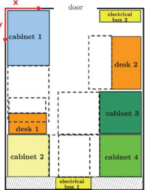
The proposed approach is a genetic algorithm-based frame- work [14] where the fitness function captures various factors that contribute to the engagement on a given layout -

We propose new modifications of the greedy agglomerative heuristic algo- rithms with local search in SWAP neighborhood for the p-medoid problems and j-means procedure for

0 Problem is the instance treated. 0 UB is the upper bound obtained for the Make- span in single-objective studies. 0 M I and TI are the best Makespan and Tardi-

This paper presented a new facility layout planning method of the central kitchen in food service industry by combining optimization, GA, and simulation; fitness value calculation

Even if the work of [FH15] concerns a particular optimization problem (i.e., the quadratic minimum spanning tree problem), the approach is of general interest and has been applied

The proposed algorithm relies on a joint use of two dedicated crossover operators to generate offspring solutions and an iterated double-phase tabu search procedure to improve

In the second part we consider the free endpoint Mayer problem for a controlled Moreau process, the control acting as a perturbation of the dynamics driven by the normal cone,

Sign gradient descent method based bat searching algorithm with application to the economic load dispatch problem... Sign gradient descent method based bat searching algorithm