PERFORMANCE IMPROVEMENT OF AD HOC NETWORKS USING DIRECTIONAL ANTENNAS AND POWER CONTROL
MÉMOIRE PRÉSENTÉ
COMME EXIGENCE PARTIELLE DE LA MAÎTRISE EN INFORMATIQUE
PAR QILEIBIAN
UNIVERSITÉ DU QUÉBEC À MONTRÉAL
PERFORMANCE IMPROVEMENT OF AD HOC NETWORKS USING DIRECTIONAL ANTENNAS AND POWER CONTROL
A THESIS IN
THE DEPARTMENT OF COMPUTER SCIENCE
SUBMITTED IN PARTIAL FULFILLMENT OF REQUlREMENTS FOR THE DEGREE OF MAÎTRISE ÈS SCIENCES
BY QILEI BIAN
Avertissement
La diffusion de ce mémoire se fait dans le respect des droits de son auteur, qui a signé le formulaire Autorisation de reproduire et de diffuser un travail de recherche de cycles supérieurs (SDU-522 - Rév.01-2006). Cette autorisation stipule que «conformément à l'article 11 du Règlement noa des études de cycles supérieurs, [l'auteur] concède à l'Université du Québec à Montréal une licence non exclusive d'utilisation et de publication de la totalité ou d'une partie importante de [son] travail de recherche pour des fins pédagogiques et non commerciales. Plus précisément, [l'auteur] autorise l'Université du Québec à Montréal à reproduire, diffuser, prêter, distribuer ou vendre des copies de [son] travail de recherche à des fins non commerciales sur quelque support que ce soit, y compris l'Internet. Cette licence et cette autorisation n'entrainent pas une renonciation de [la] part [de l'auteur] à [ses] droits moraux ni à [ses] droits de propriété intellectuelle. Sauf entente contraire, [l'auteur] conserve la liberté de diffuser et de commercialiser ou non ce travail dont [il] possède un exemplaire.»
Undoubtedly, the completion of this thesis benefited from the support of many individuals. First and foremost, l would like to take this opportunity to express my sincere appreciation to my supervisor, Professor Ajib Wessam, for his valuable guidance, and commitment to this project.
l want ta thank every instructor who educated and every staff member who helped me thraughout the course of my study at Université du Québec à Montréal.
l would also like to express my gratitude to Aifeng Ren at Scalable Network Teclmologies, Peter Maloney from University of Toronto, Feng Tan from the University of British Columbia, and Hisashi Koga at University of Tokyo for invaluable suggestions, assistance and discussions via email or telephone.
Finally, l would like to thank my parents, Li Tong and Jinhong Bian, for their love, constant support, and immense encouragement over the years. Without their support, it would have been impossible for me to accomplish what l have accomplished. l am extremely indebted to my fiancée, Hui Zhou, for being beside me through the best and worst of times. She has been my partner in every possible way during my long Master's joumey.
TABLE OF CONTENT
LIST OF FIGURES viii
LIST OF TABLES x LIST OF ACRONYMS xi RÉSUMÉ xiv ABSTRACT xv CHAPTER 1 n\TTRODUCTIOl\T 1
1.1 General concept of ad hoc networks 1
1.2 Application and usage scenarios 2
1.3 Research problem and goals 3
1.4 Thesis organization 5
CHAPTER II
TECHNICAL BACKGROUND 7
2.1 Introduction 7
2.2 The IEEE 802.11 standard 7
2.2.1 IEEE 802.11 architecture and protocols 7
2.2.2 The distributed coordinate function (DCF) 10
2.2.3 Carrier sense multiple access with collision avoidance (CSMA/CA) 10
2.2.4 Virtual calTier sense 12
2.3 Smart antennas technologies 15
2.3.1 Background of smart antennas 15
2.3.2 Switched beam antennas 16
2.3.4 Need for smart antennas 20
2.4 Summary 21
CHAPTERIII
AD HOC MAC PROTOCOL WITH DIRECTIONAL ANTENNAS 22
3.1 Several issues arising from directional communication 23
3.1.1 The weil known hidden terminal problem 24
3.1.2 Minor lobes problem 26
3.1.3 Deafness problem 27
3.1.4 Higher directional interference problem 27
3.2 The directional MAC (DMAC) scheme 28
3.2.1 Protocol description: DMAC scheme 1: utilizing DRTS packet... 28 3.2.2 The DMAC scheme 2: utilizing both DRTS and ORTS packets 29
3.3 The multihop RTS MAC (MMAC) scheme 30
3.3.1 Protocol description: multihop RTS MAC (MMAC) 30 3.4 The directional virtual carrier sensing (DVCS) scheme 31
3.4.1 Protocol description: DVCS scheme 32
3.5 Other directional MAC schemes 34
3.6 Summary and comparison 34
CHAPTERIV
POWER CONTROL IN AD HOC NETWORKS 36
4.1 Ornnidirectional antenna based power control mechanisms 37 4.2 Power control schemes using directional antennas 38 4.2.1 Power control mechanisms in multi-channel MAC protocols .41 4.3 The proposed power controlled directional MAC protocol 43
4.3.1 Unique points of our work 43
4.3.2 Operation of PCDVCS protocol 45
Vil
4.4 Summary 47
CHAPTER V
SIMULATION RESULTS 48
5.1 Introduction to QualNet simulator 48
5.1.1 QualNet GUI 49
5.1.2 QualNet protocol stack 51
5.1.3 QualNet simulation approach 54
5.2 Implementation ofPCDVCS protocol on QualNet 55
5.2.1 QualNet source file organization 56
5.2.2 Directional antenna model used in QualNet simulator 57
5.3 Simulation scenarios and results 59
5.3.1 Common parameters 59
5.3.2 Scenario 1: two nodes scenario 60
5.3.3 Scenario 2: randomly generated topology with CBR 63 5.2.4 Scenario 3: heterogeneous wireless ad hoc network scenario 67
5.4 Summary 71
CHAPTER6
CONCLUSIONS AND SUGGESTIONS FOR FUTURE WORK 72
6.1 Conclusions of the thesis 72
6.2 Future work 73
2.1 IEEE 802.11 protocol architecture 9
2.2 Basic operation ofCSMNCA 12
2.3 Hidden tenninal problem 13
2.4 Virtual carrier sense 14
2.5 Solution for hidden tenninal 14
2.6 Block diagram of switched beam antennas , 16
2.7 Switched beam coverage pattern 17
2.8 Adaptive array antenna pattern 19
2.9 Typical adaptive array smart antenna system 20
3.1 Simultaneous transmission when using directional antennas 23
3.2 A common example scenario 25
3.3 DMAC scheme 1&2 29
3.4 Multihop RTS MAC scheme 31
4.1 An example of packet transmission timeline of the MAC protocol 40
4.2 Packets transmission using PCDVCS .45
5.1 QualNet GUI screenshot 50
5.2 Implemented protocols in QualNet 51
5.3 Protocol finite state machine 53
5.4 Packet life cycle 54
5.5 Simulation study life cycle for network models 54 5.6 Switched beam antenna radiation pattern in QuaINet.. 58 5.7 Electronically steerable antenna radiation pattem in QuaINet.. 58
5.8 Network throughput in scenario 1 62
5.9 Transmission power consumption in scenario 1 62
5.10 Network throughput vs. number of packets 65
5.11 Power consumption vs. number of packets 65
IX
5.13 Transmission power consumption in scenario 2 66
5.14 Network throughput vs. number of packets 69
5.15 Power consumption vs. number of packets 69
5.16 Network throughput in scenario 3 70
3.1 Four proposed MAC schemes compare with IEEE 802.11.. 35
5.1 Qua1Net source code directories 57
5.2 Simulation parameters of scenario 1 : 61
5.3 Simulation parameters of scenario 2 63
LIST OF ACRONYMS
4G The Fourth Generation wireless communications technology
ACK Acknowledge
ADC Analog to Digital Converter
AOA Angle of ArrivaI
AODV Ad Hoc On-Demand Distance Vector Routing
AP Access Point
BER Bit Error Rate
BFN Beamforming Network
BM Butler Matrix
CBR Constant Bit Rate
CDMA Code Division Multiple Access
CMA Constant Modulus Aigorithm
CRC Cyclic Redundancy Check
CSMA/CA Carrier Multiple Sense Access with Collision Avoidance CTS Clear To Send
DCF Distributed Coordination Function
DCTS Directional CTS
DES Discrete Event Simulator
DIFS DCF IFS
DSP Digital Signal Processing
DSSS Direct Sequence Spread Spectrum
DVCS Directional Virtual Carrier Sensing
EIFS Extended Inter-Frame Spacing
FDMA Frequency Division Multiple Access
FHSS Frequency Hopping Spread Spectrum
GloMoSim Global Mobile Information System Simulator GPS Global Positioning System
GSM Global System for Mobile Communications
GUI Graphical User Interface
IFS Inter-Frame Spacing
IR Infrared
ISM Industrial-Science-Medical LAN Local Area Network LLC Logical Link Control
LMS Least Mean Square algorithm,
MAC Media Access Control NAV Network Allocation Vector
NS2 Network Simulator 2
OFDM Orthogonal Frequency Division Multiplexing
OSI Open Systems Interconnection
XIII PCS PDA PPS QoS
RF
RLS RTS Rx SDMA SIFS SINR SIR SMI SNT TCP/IP TDMA Tx VCS WiFi WLANPhysical Carrier Sensing
Personal Digital Assistant Packet Per Second
Quality of Service
Radio Frequency
Recursive Least Square algorithm
Ready To Send Receive
Space Division Multiple Access
Short IFS
Signal to Interference and Noise Ratio
Signal-to-Interference Ratio
Sample Matrix Inversion algorithm
Scalable Network Technologies
Transport Control ProtocollInternet Protocol
Time Division Multiple Access
Transmit
Virtual Carrier Sensing Wireless Fidelity
Au cours de la dernière décennie, un intérêt remarquable a été éprouvé en matière des réseaux ad hoc sans fil capables de s'organiser sans soutien des infrastructures. L'utilisation potentielle d'un tel réseau existe dans de nombreux scénarios, qui vont du génie civil et secours en cas de catastrophes aux réseaux de capteurs et applications militaires. La Fonction de coordination distribuée (DCF) du standard IEEE 802.11 est le protocole dominant des réseaux ad hoc sans fil. Cependant, la méthode DCF n'aide pas
à
profiter efficacement du canal partagé et éprouve de divers problèmes tels que le problème de terminal exposé et de terminal caché. Par conséquent, au cours des dernières années, de différentes méthodes ont été développées en vue de régler ces problèmes, ce qui a entraîné la croissance de débits d'ensemble des réseaux. Ces méthodes englobent essentiellement la mise au point de seuil de détecteur de porteuse, le remplacement des antennes omnidirectionnelles par des antennes directionnelles et le contrôle de puissance pour émettre des paquets adéquatement. Comparées avec les antennes omnidirectionnelles, les antennes directionnelles ont de nombreux avantages et peuvent améliorer la performance des réseaux ad hoc. Ces antennes ne fixent leurs énergies qu'envers la direction cible et ont une portée d'émission et de réception plus large avec la même somme de puissance. Cette particularité peut être exploitée pour ajuster la puissance d'un transmetteur en cas d'utilisation d'une antenne directionnelle. Certains protocoles de contrôle de puissance directionnel MAC ont été proposés dans les documentations. La majorité de ces suggestions prennent seulement la transmission directionnelle en considération et, dans leurs résultats de simulation, ces études ont l'habitude de supposer que la portée de transmission des antennes omnidirectionnelles et directionnelles est la même. Apparemment, cette supposition n'est pas toujours vraie dans les situations réelles. De surcroît, les recherches prenant 1'hétérogénéité en compte dans les réseaux ad hoc ne sont pas suffisantes. Le présent mémoire est dédié à proposer un protocole de contrôle de puissance MAC pour les réseaux ad hoc avec des antennes directionnelles en prenant tous ces problèmes en considération.ABSTRACT
The past decade has witnessed a remarkable interest in wireless ad hoc networks that operate without any infrastructure support. The potential for deployment of such networks exists in many scenarios ranging from civil and construction engineering, and disaster relief to sensor networks and military applications. The IEEE 802.11 Distributed Coordination Function (DCF) is the dominant MAC protocol for wireless ad hoc network. However, the DCF method could not utilize shared channel efficiently and suffers from various problems such as exposed and hidden terminal problems. Therefore, in recent years, various methods have been developed to address these problems and accordingly increase the overall network throughput, which mainly involves adjusting the carrier sensing threshold, replacing the ornnidirectional antennas by directional antennas and controlling packet transmission power adequately. Directional antennas offer numerous advantages over ornnidirectional antennas and thus could enhance the performance of ad hoc networks. They focus energy only in the target direction and offer longer transmission and reception ranges for the same amount of power. This feature could be used to adjust the power of the transmitter when a directional antenna is in use. Sorne power controlled directional MAC protocols have been proposed in the literature. Most of these proposais consider only directional transmission and, in their simulation studies, they usually assume the communication range of ornni and directional antennas are the same. Apparently this assumption is not supported in any realistic situation. Moreover, there is a lack ofwork that considers the heterogeneity in ad hoc networks. In this thesis, we propose a suitable power controlled MAC protocol for ad hoc network with directional antennas by taking ail of these issues into consideration.
INTRODUCTION
1.1 General concept of ad hoc networks
Wireless networks, which use electromagnetic waves for transmitting information through the air in order to connect two or more terminaIs, are currently gaining popularity. There are two possibilities for enabling wireless communications: infrastructure mode and ad hoc mode. The first one relies on infrastmcture that needs to be built in advance. In 802.11 infrastructure mode, aH the wireless devices in the network can communicate with each other through an Access Point (AP) or communicate with a wired network as long as the AP is connected to a wired network. The other choice is ad hoc mode whose major feature is the nonexistence of supporting stmcture.
From the perspective of the fourth Generation (4G) communication, support of ad hoc networking (MANET) is one of the requirements for 4G system [1]. Each terminal having ad hoc capability could behave as a router, forwarding traffic to other terminaIs and the base station. In the scenario in which terminaIs are out of the range of a base station, or do not have enough network interfaces, terminaIs could still reach the operator's infrastmcture via other terminaIs. Thus the 4G networks could increase their coverage to a shadow region where it would be prohibitively costly or unfeasible to have radio coverage provided by base stations [2].
2
The phrase "ad hoc" cornes from the Latin which literally means "for this purpose" [3]. The nodes in ad hoc networks are' autonomous; they could be laptop computers, Personal Digital Assistants (PDAs), sensors, or mobile phones. The autonomous nodes can self-organize and self-manage the network without requiring fixed infrastructure such as a base station or central controller. Nodes in an ad hoc network are free to join, move around, and leave the network without any restriction. Ad hoc networks are able to recover and continue to be functional in the case of link breakages. For instance, when nodes leave the network or nodes' hardware breaks down, the nodes that lost their links could simply ask for new routes, then the new routes can be established and the network can maintain connectivity and reachability. Each individual node in ad hoc network is not only a host with responsibility for sending or receiving packets but a router that takes charge of forwarding packets to other nodes. If the source and the destination are not in one hop range, they use the intermediate nodes to forward the packets ..In this case, the intermediate node would act as a router.
1.2 Application and usage scenarios
The characteristics of ad hoc networks make them weil suited for a variety of scenarios such as military applications and low cost commercial applications where infrastructure does not exist or to build one would be too costly. The following are sorne examples where ad hoc networks can be used.
In military scenanos, aircraft are able to form an ad hoc network in the sky to communicate with one another and present a backbone for land platforms to communicate with them. The infantry can establish an ad hoc network immediately when they arrive at a battlefield to achieve communication requirements like voice, telemetry, and video. For mobile objects including warships, tanks, vehicle, and
aircraft, an ad hoc network can be fonned by requiring only that each object to be within the range of its closest neighbours while traditional radio technology requires a range which covers the entire topology of the network [4].
In the disaster recovery field, for example an earthquake where the supporting structures are damaged, ad hoc networks can be set up within hours to address the need of organizing and managing different search and rescue groups to work efficiently. Wireless sensor networks are another application of ad hoc networks in which sensor devices are connected in open peer-to-peer ad hoc network architecture to offer various utilizations such as monitoring traffic congestion in a city, detecting a biological weapon in the battle field and border intrusion.
Wireless mesh networks could be considered as a type of wireless ad hoc networks. Compared with mobile ad hoc networks in which routing nodes are mobile, the routing nodes in mesh networks are stationary. These mesh nodes together establish the backbone of the network. The clients' non-routing mobile nodes connect to the mesh nodes in order to use the backbone to communicate with one another and with the Internet-connected nodes to obtain Internet access. Mesh networks extend the reach of wireless networks and are ideaUy suited for many environments such as commercial zones, neighborhood communities and university campuses [5] [6].
In summary, Wireless ad hoc networks exhibit many unique features such as easy deployment, self-organization, direct peer-to-peer communication, and maintenance free operation. There is a huge demand for developing ad hoc networks in various applications.
1.3 Research problem and goals
4
omnidirectional antennas. With the continuing reductions in the size and cost of directional antenna in recent years, it has become feasible to use directional antennas for ad hoc networks. However, the use of directional antennas in ad hoc networks introduces sorne new problems, which include the deafness problem, hidden terminal problem, and higher directional interference problem. The IEEE 802.11 MAC protocol is designed to exploit omnidirectional antennas and could not work weil in directional antenna based ad hoc networks. Therefore, several modified MAC protocols have been proposed to exploit directional antennas, enhance the spatial reuse, and increase network capacity.
On the other hand, integrating transmission power control algorithms into directional MAC protocols is another method to improve the performance of ad hoc networks and has received increasing interest in recent years. Sorne power controlled based directional MAC protocols have been proposed. To my knowledge, most of these works consider only directional transmission and they ignore the heterogeneity of ad hoc networks which means nodes in ad hoc networks could be equipped with different network facilities (sorne with directional antennas and sorne with omnidirectional antennas). In this thesis, we take heterogeneity into consideration and propose a power control mechanism in a purely directional MAC protocol which enables both directional transmission and reception of ail control and data packets.
The objectives of this master's thesis are to:
• Present a general understanding of ad hoc networks.
• Present the important concepts of the MAC layer and the physical layer of the conventional IEEE 802.11 standard that are widely used in ad hoc networks as weil as an overview of smart antenna technology ranging from very
fundamental elements to detai1ed discussion of switched beam and adaptive antennas.
• Analyze the MAC layer problems and challenges when usmg directional antennas in ad hoc networks. Study and compare several recently proposed MAC protocols that aim to better exploit the benefits of directional antennas.
• Illustrate the effects of transmission power control in ad hoc networks as weIl as review the current proposaIs conceming power control schemes in the context of both omnidirectional and directional antenna-based MAC protocols. Propose a suitable power controlled directional MAC protocol.
• Introduce the concept of QualNet simulator, its architecture and directory structure, its implementation of various protocols and its operation. Implement our proposed protocol in QualNet and compare it with other protocols so as to evaluate the performance improvement of ad hoc networks.
1.4 Thesis organization
The rest of the thesis is organized as follows. In Chapter 2, we describe the conventional IEEE 802.11 protocol used for ad hoc networks when terminaIs are equipped with omnidirectiona1 antennas, including Distributed Coordinate Function (DCF), Carrier Multiple Sense Access with Collision Avoidance (CSMAlCA) and virtual carrier sense mechanisms; we also present the concepts of smart antennas from a technical point of view. In Chapter 3, we firstly present the MAC layer challenges of using directional antennas in ad hoc networks, then we discuss and compare several directional antenna-based MAC protocols that have been proposed in the literature in recent years. Chapter 4 presents several power control schemes in wireless ad hoc networks, which includes the power control schemes using both
6
omnidirectional antennas and directional antennas. Our proposed power controlled MAC protocol, which is based on DVSC (Directional Virtual Carrier Sensing) protocol, is also described in this chapter. In Chapter 5, the simulation results for the proposed protocol are presented and compared to the IEEE 802.11 protocol and conventional DVCS protocol that do not include an integrated power control scheme. The simulation software is also discussed in this chapter. Finally, Chapter 6 provides a summary of the thesis and sorne directions for further work.
TECHNICAL BACKGROUND
2.1 Introduction
In this chapter, we present an overview of the conventional IEEE 802.11 standard that is widely used in ad hoc networks, as weil as the concepts of smart antenna technology. Section 2.2 focuses on IEEE 802.11 architecture and protocols. The IEEE 802.
n
distributed coordinate function, CSMAJCA and VCS (Virtual Carrier Sensing) mechanism are presented in detail. In section 2.3, we discuss two kinds of smart antenna: switched beam and adaptive array.2.2 The IEEE 802.11 standard
2.2.1 IEEE 802.11 architecture and protocols
IEEE 802.11, or WiFi, is a set of WLAN standards developed by Working Group Il of the IEEE LAN/MAN Standards Committee (IEEE 802). It supports two operation modes: the ad hoc mode which allows peer-to-peer communication between mobile terminais and the infrastructure mode in which mobile terminais communicate through the supporting structure such as a base station or an access point. The operating frequencies of IEEE 802.11 contain two Industrial-Science-Medical (ISM) frequency bands: 2.4GHz and 5.8GHz. The original 802.11 WLAN specification was published in 1997 and c1arified in 1999. Moreover, there are still sorne 802.11
S
standard amendments being used, such as S02.lld for scanning scheme, S02.llk for Quality of Service (QoS), S02.ll i for enhanced security, S02.ll r for fast roaming and S02.ll s for mesh networking. The most popular and widely used amendments are the S02.ll a, S02 .11 band S02.ll g protocols.
IEEE S02.lla uses the same core protocols as the original standard and operates in the unlicensed 5GHz band. It utilizes the 52-subcarrier orthogonal frequency division multiplexing (OFDM) as physical transmission scheme and has a maximum raw data rate of 54Mbit/s.
IEEE S02.ll buses another unlicensed 2.4GHz band and employs the same CSMA/CA media access method defined in the original standard. Due to CSMA/CA protocol overhead and channel conditions, IEEE S02.ll b has a lower maximum raw data rate (Il Mbit/s) when compared with IEEE S02.ll a.
IEEE S02.ll g works in the same frequency band as S02.ll b (2.4GHz) and uses the same physicallayer protocol as S02.lla (OFDM). It supports a raw data rate up to 54 Mbit/s.
LflJ:\('1l1 tlnk Conlrol COl'ltClll.IolI·rrcc s('n-iç('
i
+
CIIOIClIli'olll ~rvice Point Coordiool1on ~'unctlon (P,C~") 1 :\1i\C Llly(·rDistribut~d CoordinRtl<ln Funclion
(DC"')
~
2.4 (;117. 2.4Gh~ tnrrllr('() ::> Ch" 2.4 GI17.
t'rt'(jucnC) direct 1 Mbps orthOj{oml1 direct hoppillll ~Cluco.:e ;li\"b~ FOM ~C<lucncc
sprc:ad "pl"t!ad 6,9.12. sprelJd
lS'JX'ë1l'ul11 ,,-pceh'ul'rl 18, U, 36, SpcctfUI\1
1 :\tbps 1 Mb(>'i ~S~ :\lbps S.S :\lbll~
2 \\1bW> 2 Mbp5 Il i\1bps
'--
----...,._---"----_-.A...---v--...-J
mm·: Slll.ll IEf.f: l!U~.llll lI·:f.f.l>O~.llb
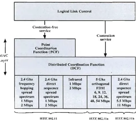
Figure 2.1: IEEE 802.11 protocol architecture
The IEEE 802.11 family specifies both the MAC layer and the PHY (physical) layer of the OSI (Open Systems Interconnection) model for wireless networks. Figure 2.1 illustrates the IEEE 802.11 protocol architecture. The PHY layer describes the specifications conceming different choices of RF technologies to use, such as Frequency Hopping Spread Spectrum (FHSS), Direct Sequence Spread Spectrum (DSSS), infrared (IR), and Orthogonal Frequency Division Multiplexing (OFDM). The purpose of the MAC layer is to provide a control mechanism that allows multiple users to use the shared channel efficiently. The data link layer is divided into two layers: the logical link control (LLe) layer and the MAC layer. The MAC layer provides two different types of service: the contention-based service offered by the Distributed Coordination Function, and the contention-free service offered by the Point Coordination Function (PCF). The DCF service is based on the CSMAICA scheme and offers the basic access method of the 802.11 MAC protocol. The PCF is
la
implemented on top of DCF service to support infrastructure-based wireless communication where tenninals communicate via access points. Note that, the PCF service is not available for use in ad hoc mode.
2.2.2 The distributed coordinate function (DCF)
The basic 802.11 MAC layer uses Distributed Coordinate Function to allow communications between multiple mobile node pairs in the absence of an access point or base station. DCF is based on the mandatory CSMA/CA mechanism and the optional 802.11 RTS/CTS (Ready to Send/ Clear to Send) handshaking mechanism. According to DCF, a station must monitor the channel to detennine whether there is any other station transmitting data before starting data transmission. If the channel is busy, the stations wait until the medium becomes idle. If any two stations are pennitted to transmit by the protocol simultaneously immediately after the medium becomes idle, then collisions occur. In order to solve this problem, CSMA/CA defines various kinds of backoff time named "inter-frame spacing." A station intending to access the medium utilizes the inter-frame spacing (IFS) to prevent collisions from happening. In addition, the RTS/CTS handshaking mechanism is used
\
with the aim of solving the hidden tenninal problem.
2.2.3 Carrier sense multiple access with collision avoidance (CSMA/CA)
CSMA could be considered as a Time Division Multiple Access (TDMA) mechanism due to the fact that it allows multiple mobile stations to compete for use of the shared medium at different time slots in order to avoid the occurrence of collisions. On the other hand, CSMA could also be considered as a kind of Space Division Multiple Access (SDMA) mechanism because transmissions among several mobile node pairs are permitted to take place simultaneously without interfering with each other when
mobile stations are equipped with directional antennas. According the CSMA/CA mechanism, ail stations are obliged to remain silent for IFS. Various IFS are specified in the IEEE standard [7] with the objective of prioritizing different frame transmissions. High priority frames only wait for the short IFS (SIFS) period before they compete for channel access. The DCF IFS (DIFS) is adopted to transmit data frame. Extended inter-frame spacing (EIFS) is used when source station detects the Data Corruption.
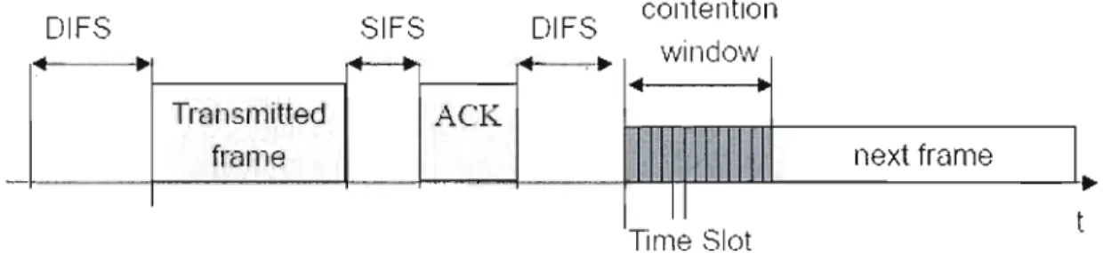
CSMA/CA mechanism works as illustrated in Figure 2.2. A source node wishing ta transmit senses the channel to determine the status of the medium. If no activity is detected for a period of DIFS, the source node can use the channel to transmit. If activity is detected during the period of DIFS, the backoff timer is activated. In this case, the source node waits until the medium becomes idle and then continues ta sense the medium for a period ofDIFS together with an additional, randomly selected backoff time. If the medium is always idle during the sensing duration, the source node could start transmitting data. If the source node senses that the medium has become busy again within the sensing duration, it stop downcounting the backoff timer and waits until the medium becomes idle and then senses the medium again for a new DIFS and the remaining backoff time. If the medium remains idle during this sensing duration, the source node begins to transmit data; otherwise it repeats this procedure until the backofftimer reaches the value zero.
Upon reception of data frame, if the bit error rate (BER) of the received data frame is under the threshold limit, the receiving node initiates the transmission of an acknowledgement frame (ACK) after a SIFS time period. On the reception of this ACK, the source node knows that this process is completed. On the other hand, the receiving node will not issue an ACK frame if the data frame is corrupted. The receiving node use the cyclic redundancy check (CRC) algorithm for error detection.
12
If the ACK is not received by the source node, the data frame is assumed to have been corrupted or lost, and the data packet will be scheduled to be retransmitted later.
contention
DIFS SIFS DIFS
window
...
..
...
,'"
TransmiUed ACK
frame next frame
1 - - - t - - - f - - - J - . - - - . f - - - f ' l = I l . b I = t . . b l = l - b 6 . l = l l - - - L.•
Time Siot Figure 2.2: Basic operation of CSMA/CA
2.2.4 Virtual carrier sense
In the IEEE 802.11 standard, two kinds of carrier sensing mechanisms are defined, aiming at avoiding collisions in a channel. They are Physical Carrier Sensing (PCS) and Virtual Carrier Sense (VCS). PCS works in physical layer by detennining the signal strength to detect collisions. However, its RF hardware is expensive to build. Another PCS issue is that it is not able to solve the well known hidden terminal problem which will be demonstrated in detail in the next paragraph.
The hidden tenninal problem happens when two source stations send packets to the same destination station simultaneously due to lack of awareness of each others existence. As an example, in the following scenario, shown in Figure 2.3, source station "A" is sending packets to "B". Another source
"c"
also intends to send packets to "B" because C is out of the transmission range of A and hence can not physical carrier sense the ongoing transmission of A. In other words, A is "hidden" for C. So, source"c"
starts to send packet to "B". Thus, a collision occurs and consequently reduces the network throughput significantly.Figure 2.3: Hidden tenninal problem [8]
Yirtual Carrier Sense works in the MAC layer and offers a good solution to the hidden terminal problem by using Network Allocation Yector (NAY) and RTS/CTS handshaking mechanism. NAY is a timer that specifies the time period during which the station is not allowed to transmit. Figure 2.4 illustrates how the YCS works. At first, a source station wishing to transmit broadcasts an RTS packet which includes the information of the source address, destination address, and the duration of the transmission to follow. By receiving the RTS packet, the destination station responds with a CTS packet if the medium is idle after an SIFS time. The CTS packet includes the same information as the RTS packet. The neighbors of both source station and destination station overhear the RTS and/or the CTS and set their YCS timer according to the duration info specifIed in RTS/CTS packets. The surrounding stations then use this infonnation to schedule the time for the next medium sensing. This process guarantees a station which did not receive the RTS is able to hear the CTS and set its YCS accordingly. RTS and CTS frames are very small in size when compared with the data frame. As a result, if any collision happens during the RTS/CTS handshaking, the bandwidth waste is very small compared to the case where collision happens during the data frame transmission (when not employing RTS/CTS mechanism).
14
DIFS
-RTS data
sender
SIFS t - - SIFS SIFS f -
crs
ACK receiver DIFS NAV (RTS) other Il data NAV (CTS) 1 stations 1 t defer access contention Figure 2.4: Virtua1 carrier sense [8]An example of VCS is explained below as shown in Figure 2.5. First, source station A broadcasts an RTS to its neighbors: Band D. Upon receipt of the RTS, Node D finds the RTS is not for itself, so it defers its transmission. And the destination station B then sends back a CTS to A. It is obvious that node C can hear this CTS packet because it is within the transmission range of station B. thus station C also updates its NA V according to the duration infonnation that encapsulated in CTS and defers its transmission. Thus, this process solves the hidden tenninal problem and prevents interferences during data transmission between station A and B.
0f--_RT_S_~)f--_:_:S_S
---;01---
CT
-S
--i(0
DATA
ACK
Figure 2.5: Solution for hidden terminal [8]
2.3 Smart antennas technologies
2.3.1 Background of smart antennas
In contrast to the enormous bandwidth available in optical fiber networks, the electromagnetic spectrum resources in wireless communication systems are limited. In order to maximize the efficient use of spectrum, sorne multiple access technologies have been developed. The first generation (1 G) system for mobile telephony was analog and it employed the Frequency Division Multiple Access (FDMA) technique to allow different subscribers to communicate at the same time by using different frequencies. An example of a second generation (2G) system is the digital Global System for Mobile Communications (GSM) standard and it adopted the Time Division Multiple Access (TDMA) technique to allow different subscribers to use the same frequency in different time slots. Third generation (3G) systems utilized the Code Division Multiple Access (CDMA) technique and enabled different subscribers to communicate simultaneously on the same frequency through the use of unique spreading codes. Smart antenna technology born in 1960s introduces a new multiple access method: Spatial Division Multiple Access (SDMA). The SDMA mechanism enables different subscribers who are separated in space to communicate simultaneously using the same frequency and same spreading codes [9] [10]. Smart antennas have been widely deployed in various communication systems to improve wireless network capacity and resolve performance challenges.
An antenna in a communications system is a kind of the port through which Radio Frequency (RF) energy is radiated from the transmitter to the outside space for transmission purposes, and in reverse, from the outside space to the receiver for reception purposes. An omnidirectional antenna (also known as an isotropic antenna) radiates or receives RF energy equally in ail directions. Smart antennas actually should be referred to as smart antenna systems because the antenna is not smart. It is
16
the antenna system that can control the antenna array intelligently to form a directional radiation pattern. The smart antenna can be considered a pattern controllable antenna. It consists of a number of antenna elements arranged spatially and interconnected electrically through complex weights. The radiation pattern of the antenna array is determined by the weights based on Digital Signal Processing (DSP). Smart antenna systems could be classified into two categories: switched beam antenna and adaptive array antenna [11] [12] [13].
2.3.2 Switched beam antennas
The switched beam smart antenna system is a simple and cheap technology. It merely employs a basic switching function for selecting among separate antennas or predefined array beams. Figure 2.6 presents a basic switched beam antenna architecture which contains a control logic unit for beam selection, a switch .unit for activating the right beam and a BeamForming Network (BFN).
_ T x 5oV./lt(11 RC\IT RCVT
J
_ - - s " , . , m _ _ _ _ _ _ _ _ _ _ _ _ "",I€<OlIonAs an example in a cellular communication system, a base station equipped with the switched beam system could detect the signal strength and choose the beam that offers the highest SINR (Signal to Interference and Noise Ratio). As the cellular phone moves throughout the sector, the base station would switch from one beam to another to achieve the best perfonnance if required, as illustrated in Fig. 2.7. Only a single beam pattern could be used at any given time. Such an antenna system cou Id increase coverage range up to 200 percent over conventional sector cells depending on the propagation environment, hardware and software used. It cou Id also suppress interference arriving from directions away from the active beam's center. However, from Figure 2.7 we should notice one shortcoming of the switched beam system is that the limited predefined main beams are only available for certain prefixed directions. In the case that the user is located between two predefined main beams, the base station is not able to achieve any directional gain from the antenna system although we could increase the number ofbeams to mitigate this problem [14].
18
Switched beam smart antenna systems work weil in c1ean areas with low or no interference. However, in high interference environments, switched beam antennas are further limited due to their predefined fixed beam characteristic and the fact that they lack the ability to reject interference.
2.3.3 Adaptive array smart antenna systems
Compared with switched beam which only allows base stations to switch among several fixed beams in predetermined directions, the adaptive antenna is capable of steering main beams dynamically towards desired users and null toward interfering signais by using advanced signal processing teclmiques. In other words, by employing advanced signal processing functionality, the adaptive array has the ability to adapt to radio environment changes such as a user's movement. When a user is moving, the adaptive array system changes its antenna pattern smoothly to follow the user, always providing highest gain in the user's direction. Figure 2.8 illustrates the pattern of an adaptive antenna system. It shows the main lobe coverage extension toward the target user and nulls directed toward two interferers. The core idea of adaptive beamforming is to change the complex weight value of each element according to the changing radio environment. By multiplying these complex weight values to the output of each element, the system is able to generate the desired radiation pattern that matches the traffic conditions and offers the highest beam gain in the desired direction. Many adaptive algorithms have been deve10ped aiming to compute the optimal complex weight which contains amplitude and phase information used for beam steer. Note that the direction of the main beam is determined by amplitudes and phases of the antenna elements of the adaptive array system.
Figure 2.8: Adaptive array antenna pattern [16]
Adaptive algorithms could be classified into two categories: blind adaptive algorithms which require no reference signal and non-blind adaptive algorithms which require reference signal [17]. An example of blind adaptive algorithm is constant modulus algorithm (CMA) where the algorithm itself generated the required reference signal from the received signal based on the characteristics of the received signal structure. On the other hand, in non-blind adaptive algorithms, the reference signal that has a high correlation with the desired signal is provided. Examples of trained adaptive algorithms consist of Least Mean Square (LMS) algorithm, Recursive Least Square (RLS) algorithm, Sample Matrix Inversion (SMI) algorithm. According to these algorithms, the training signal is sent from the transmitter to the receiver during the training period and used by the algorithm to update its complex weights.
Figure 2.9 presents a typical adaptive array antenna system. From this figure, it is obvious that Digital Signal Processing is the key technology. This is because numbers of dynamic adjusting functionality of adaptive antenna system rely on DSP. Before the digital signal processor is able to work, the received analog signal must first be downconverted to baseband frequency. Next; the Analog to Digital Converter (AOC) will take charge of converting it ta digital format.
20
w*
PInne \\"nw r--··_····_···,--·..-...--.----_!
Allrellllîl i , , Do.\ (.\)I(/lÎn!) DSPAITay 1, RofHNlce 01 .\ci:lprin
!.>ignnl .~l:l.u ilLIll (Temporal)
/
Î:.
DSP
_
_
-_ - _--_ .._-_ .. _-_._---_._,Figure 2.9: Typical adaptive array smart antenna system [18]
2.3.4 Need for smart antennas
There are many motivations to utilize the smart antenna technique in a wireless system. As an example of a cellular communication system where the capacity has become a critical issue, the use of conventional omni-directional antennas not only causes huge waste of signal energy because only a small part is transmitted to desired receiver but also generates serious interference to neighboring base stations and terminais. Therefore, the sectorization mechanism which divides one cell into several sectors and uses a directional antenna for transmission was developed with the goal of reducing the interference level. Sectorized systems have shown ability to increase frequency spectrum utilization and therefore support more capacity benefits from the sectorization gain. However, sectorized systems lack the ability to change the antenna's beamwidth or orientation in response to a changing propagation environment and traffic condition. This shortcoming results in large capacity waste in sparse traffic sectors and traffic blocks in dense traffic sectors [13]. The adaptive array smart antenna system which can intelligently control its radiation pattern based on signal processing provides an excellent solution to these problems. As we have mentioned before, its feature of focusing a narrow beam towards the target receiver
increases coverage of the base station and allows the base station to decrease the transmission power to save battery power. Its feature of generating null towards interferers results in higher frequency spectrum utilization and thus increases the system capacity. And its feature of multipath rejection helps to alleviate the negative effect of multipath and diminish the effective channel's delay spread, hence results in less power loss, higher bit rate, and better QoS.
The smart antenna technique is applicable for almost all CUITent major wireless protocols and industrial standards to achieve larger network coverage and higher system capacity. Examples of these standards cou Id be FDMA employed in AMPS, TACS and NMT; TDMA employed in GSM and IS-136; CDMA employed in IS-95, WCDMA and TD-SCDMA; FDD and TDD [13]. As its costs continue to decline, the smart antenna offers a practical, economical solution to address wireless network capacity and performance challenges for different communication systems, including RFID, WiMax, U1trawideband (UWB), and even WiFi.
2.4 Summary
In this chapter, important concepts of the MAC layer and physical layer of IEEE 802.11 standards and concepts of smart antenna technology have been presented. The mechanisms of CSMAlCA, VCS are discussed in detail. The 802.11 MAC protocol addresses the hidden terminal problem by using the RTS/CTS mechanism and works well when nodes in the network are equipped with traditiona1 ornnidirectional antennas. Furthermore, two main kinds of smart antenna, switched beam and adaptive aITay antenna are discussed in de~ail. We present the need for using smart antennas. Smalt antennas could be used in many different communication systems including WiFi.
CHAPTERIII
AD HOC MAC PROTOCOL WITH DlRECTIONAL
ANTENNAS
In the previous chapter, we have presented the conventional IEEE 802.11 standard and smart antenna technologies. Smart antenna technology offers many benefits and plays a key role in 3G and 4G systems. It has been broadly used in various communication systems. However, to simply use directional antenna with the conventional IEEE 802.11 standard for ad hoc network could not bring substantial network improvements and sometimes even deteriorates network performance. This motivates many research groups to develop new MAC protocols which could fully exploit the advantages of directional antennas. This chapter first presents the challenges introducèd by using directional antennas in ad hoc networks, fol1owed by a discussion of several new MAC protocols which have been proposed in recent years to better exploit the capability of directional antennas.
The purpose of the Medium Access Control (MAC) is to achieve efficient sharing of a common wireless channel between multiple nodes, which means to allow as many simultaneous communications as possible [19]. Medium access control mechanisms could be classified into two types: contention-based and contention-free. The most used contention-based mechanism for ad hoc networks is CSMA/CA (Carrier Sense Multiple Access with Collision Avoidance), and the most used contention-free MAC
•
•
mechanism for ad hoc networks is TDMA. In this chapter, we focus exclusively on contention-based new MAC proto cols that are designed for directional antennas.
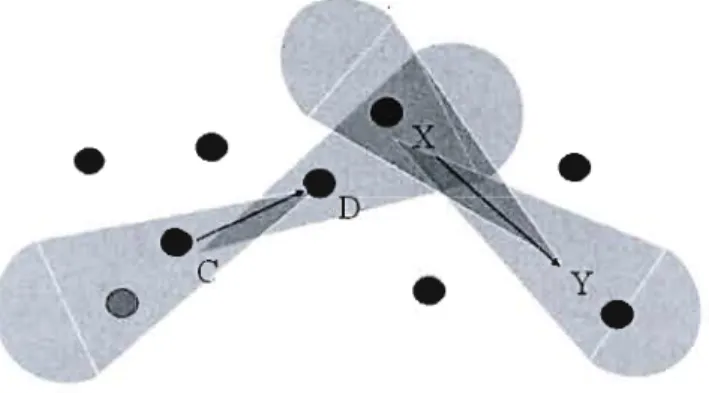
Using directional antennas in ad hoc networks could enable us to achieve numerous advantages over omni-directional antennas. A transmitter equipped with directional antennas can radiate RF energy towards its intended receiver and the receiver can also radiate RF energy towards the sender, hence providing very high antenna gain. The nodes are also capable of selectively receiving signais only from a wanted direction, thus avoiding interference from undesired directions and hence resulting in high SINR. The use of directional antennas makes it possible that more simultaneous transmissions could take place. In the scenario, shown in Figure 3.1, communications between C and D node pair and between X and Y node pair are allow to occur simultaneously. This is impossible when using onmidirectional antennas. The combined effect is to help improve system throughput and capacity.
•
C y•
•
Figure 3.1: Simultaneous transmission when using directional antennas
3.1 Several issues arising from directional communication
Conventional IEEE 802.11 is designed with the assumption that omnidirectional antennas are used at the physicallayer. Although the 802.11 MAC protocol could still
24
operate correctly when nodes are equipped with directional antennas, network performance may deteriorate due to several problems, including the hidden terminais problem and the deafness problem. These problems depend on the topology and pattern flow. In the following subsections, we will first present sorne major problems in the directional MAC design. Then, there will also be a discussion and comparison ofvarious new MAC schemes that have been proposed to alleviate these problems.
3.1.1 The weil known hidden terminal problem
To be general, a hidden terminal can be defined as a terminal that is not aware of the ongoing communication between transmitter/receiver pairs and whose intended transmission could lead to the failure of the ongoing transmitter/receiver pair's communication. Conventional MAC protocols for ad hoc networks (the IEEE 802.11 operated in ad hoc mode) address the hidden terminal prob1em by employing the
RTS/CTS handshaking mechanism before data transmission. However, this is under
the assumption that RTS/CTS packets are sent omnidirectionally. With the use of directional antenna in physical layer, RTS/CTS packets are transmitted in the directional manner (such as protocols proposed in [20], [21 J), thus two new types of hidden terminal problems arise. We explain them respectively below.
(1) Hidden terminal problem due to unequal gains in omni and direction al
modes
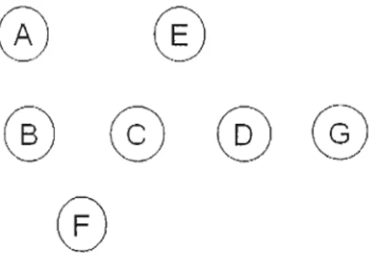
This type of hidden terminal problem is identified in [20] and can be depicted as follows. Suppose in Figure 3.2 that node D sends a DRTS (Directional RTS) and node G responds with a DCTS (Directional CTS), thus Nodes D and G beamform towards each other. Then node D starts transmitting data to G. Meanwhile, suppose that node B is in idle and listening omnidirectionally. Node B is distant enough from
node G, so it is unable to hear the DCTS from G (in OIuni listening mode) since an omnidirectional antenna has lower gain than a directional antenna. While data transmission from node D to G is in progress, assume that node B intends to communicate with C, and thus transmit a DRTS to node C using a directional antenna. It is very possible that this DRTS from B will interfere with node G because node B and node Gare now directed towards each other.
To put it simply, this type of hidden tenninal problem results from the fact that transmit and receive nodes might be out of each other's range when they are operated in omnidirectional mode and directional mode respectively. However, when they are both in directional mode, they may be within each other's range.
(À)
Œ)
(~)
@
CE)
(~)
o
Figure 3.2: A common example scenario
(2) Hidden terminal problem due to unheard RTS/CTS
This type of hidden tenninal problem results from the feature of a directional antenna that its antenna gain towards a desired direction is larger than the gain towards other directions. Consider the scenario of Figure 3.2. Assume that node Bis beamfonned in the direction of node A and is transmitting packets to A. In the meantime, node C transmits a DRTS to node D and node D responds with a DCTS. On receiving DCTS from D, node C starts sending data to D. In this scenario, node B is not able to hear
26
the RTC/CTS exchange between C and D since it is beamforrned in the direction of A. In other words, node B is unaware of the ongoing transmission in its neighborhood. While transmission between C and D is going on, suppose that B finishes its transmitting to A and now has intention to transmit a packet to D (or other node in the direction of D, like Node G). Node B sends a DRTS to node D. This leads to a collision at D because D's receiving beam is directed towards B. This type of hidden terminal problem could occur frequently when a directional antenna is used in the physical layer.
3.1.2 Minor lobes problem
Minor lobes represent a terrn used in radio engineering fields to mean any lobe except the main lobe of an antenna radiation pattern. In short, this problem arises in the case that the interferer is unaware of the ongoing transmission, and sending packets towards the minor lobes of the receiver node.
This minor lobes problem could be presents as follows. Consider the scenario of Figure 3.2 again, suppose that node B wants to transmit data to C, after a DRTS/ DCTS exchange between node Band C, node B starts transmitting data packets to node C. In the meantime, node A cannot sense the DCTS from C because it is out of the direction of the main lobe of node C. Now assume that node A intends to send data to node C and hence beamforrns its main lobe towards node C. Although node C has only a minor lobe pointing in the direction of A, collision could happen at node C due to the high gain of the main lobe of node A.
3.1.3 Deafness problem
The deafness problem [22] occurs ln the case that a transmit node fails to send packets to a target receiver which is pointing in another direction for an ongoing transmission. We explain the deafness problem using the same scenario in Figure 3.2. Assume that node Chas packets to send to node D. Node C transmits a DRTS to D and node D responses with a DCTS. Then node C starts transmitting data to D. While this transmission is in progress, node F intends to transmit to C. Note that node F is unable to hear the DRTS/ DCTS between C and D, which means, F is unaware of the transmission between C and D. Therefore, node F sends a DRTS to node C. Because node C is facing node D, node C does not receive this DRTS from node F and therefore does not reply with DCTS. On receiving no reply from C, node F increases its contention window, chooses a backoff time, and starts counting down. When the countdown reaches zero value, Node F will retransmit the DRTS. Retransmissions could continue over and over again until C finishes its transmission and retums to the ornni listening mode. This leads to huge wastage of system capacity and unfaimess because the backoff time of node F would be increased after every failed attempt.
3.1.4 Higher directional interference problem
The use of a directional antenna could increase the transmission range and hence make it possible to communicate directly with distant nodes. On the other hand, this increased transmission range could also cause interference to distant nodes. To deal with these problems, sorne proposaIs simply suppose that the transmission range of directional antennas is identical to the transmission range of omnidirectional antennas. However, this is not correct in actual practice.
28
3.2 The directional MAC (DMAC) scheme
In [23], Young-Bae Ko proposed two Directional MAC (DMAC) schemes where each node is equipped with a Global Positioning System (GPS) receiver in order to know the physical location of each node, one transceiver, and several directional antennas. Note that anode is unable to send two packets at the same time by using different directional antennas since there is only one transceiver. This proposai could be considered a per-antenna basis 802.11 protocol. It is similar to the 802.11 DCF protocol in many ways except it transmits RTS, DATA and ACK directionally and alternatively transmits CTS omnidirectionally depending on whether the antenna pattern of the transmitter is blocked. The author assumes that transmission range of a directional antenna is the same as that of an omnidirectional antenna.
3.2.1 Protocol description: DMAC scheme 1: utilizing DRTS packet
Directional MAC (DMAC) scheme 1 enables a transmit node to use a directional antenna to send RTS packets toward a desired receiver node. After the reception of RTS, the receiver node transmits a CTS packet in ail directions.
The operation ofDMAC scheme 1 could be depicted using the scenario in Figure 3.3. Suppose that node B intends to send data to C and also suppose that there are no active transmissions within B's neighborhood. Thus, Node B transmits a direction al RTS (DRTS) containing the B's physical location information to node C. Node A could not hear the DRTS from node B although node A is located within B's communication range. If C receives the DRTS from B successfully, it replies with an omnidirectional CTS (OCTS) to ail its adjacent nodes. This OCTS includes the location of node C and location of node B. After a successful DRTS/OCTS exchange, node B starts transmitting data directionally and receives a directional ACK from
Node B. One advantage of DMAC scheme 1 is that it could enable node D
ta
communicate with node E when communication between Band C is still ongoing.
..
... - --... ... ""\... ;""1.: , , , , , 1 1 1 1 , , ,,, \ \ 1 1 1 1 1 \ \, ,, , , , 1 , , , , ,Figure 3.3: DMAC scheme 1&2
3.2.2 The DMAC scheme 2: utilizing both DRTS and ORTS packets
Directional MAC scheme 2 is proposed so as to diminish the probability of collision between control packets. When compared with DMAC scheme l, the major improvement of DMAC 2 is its use of two types of RTS packet, directional RTS (DRTS) and omnidirectional RTS (ORTS). The node that has data to send would first transmit ORTS or DRTS according to the following two rules:
1) If none of its directional antennas are blocked by the ongoing transmission, an omni-directional RTS packet will be send,
2) Otherwise, if the desired directional antenna is not blocked, a directional RTS (DRTS) packet will be sent. If the desired directional antenna is blocked, the node will defer its transmission until that directional antenna becomes unblocked.
By introducing the combination of DRTS and ORTS packets, DMAC scheme 2 offers a solution which reduces the number of instances of collision between control
30
packets. Except for the two rules mentioned above that are used to determine whether anode should send ORTS or DCTS, DMAC scheme 2 is identical to scheme 1.
3.3 The multihop RTS MAC (MMAC) scheme
A Multihop RTS MAC (MMAC) scheme is introduced in [24] to exploit the higher transmission gain of directional antennas for transmission on multihop paths. The MMAC scheme can be considered an enhancement of the DMAC protocol. MMAC defines two types of neighbor nodes, Direction-Omni (DO) Neighbor and Direction Direction (DD) Neighbor. DO Neighbor refers to anode that has the ability to receive a directiona1 transmission even if it is in omni mode. Similarly, DD Neighbor refers to anode that can receive the directiona1 transmission only when its directiona1 receiving antenna has been pointed in the direction of the sender node.
MMAC utilizes directional antennas for both transmission and reception. Each node is equipped with an omnidirectional antenna and an adaptive antenna. Since directional antennas provide a higher gain and communication range than omnidirectional antennas, anode cou Id possibly communicate directly with the distant node. For that reason, MMAC utilized multiple hops to send RTS packets in order to establish connection with the node that is far away. The following CTS, data and acknowledgement packets are transmitted in single hop. MMAC could not solve the problems of deafness and hidden terminais, but it could compensate for the negative impact resulting from those problems, and therefore lead to improvement in performance.
3.3.1
Protocol description: multihop
RTS MAC (MMAC)
MMAC scheme is presented briefly as follows using the scenario in Figure 3.4. Suppose that node A has data packet for node F. According to the MMAC scheme, the neighbor nodes can be classified into DO neighbors A-B-C-F and DD neighbors
A-F. First a DRTS packet is sent by node A to F. Node D and G located between A< >F pair overhear this DRTS and hence defer transmission accordingly. When F receives the DRTS, in case that node F directs its directional antenna toward the direction of node A, the Direction-Direction (DD) link can be established directly and transmission can commence.
Otherwise, the DO neighbors would participate into the procedure of establishing the Direction-Direction communication between A<->F pair. A special type of RTS packet (called a forwarding-RTS) is used during this process. First node A transmits a forwarding-RTS packet to its DO neighbor-Node Band node B forwards it to node F via node C. Meanwhile, node A directs itself toward the direction of node F to wait for the DCTS from F. Note that node Band C forward this forwarding-RTS packet without using any backoff time and will not update their DNAV tables in order to minimize the forwarding time consumption. Upon the receipt the forwarding-RTS, destination node F initiates a CTS packet and sends it to node A directionally. When node A receives the DCTS through DD route, the Direction-Direction (DD) link could be established successfully.
Data
Figure 3.4: Multihop RTS MAC scheme
3.4 The
direction al
virtual carrier sensing (DVCS) scheme
32
is designed in [25] for mobile ad hoc networks using directional antennas. DVCS supports not only directional transmission but directional reception.
It
does not need specific physical configuration of directional antennas and external devices. Instead of relying on additional GPS devices to locate each node, DVCS only needs minimum information on Angle of ArrivaI (AÜA) and antenna gain for each signal from an underlying physical device.DVCS can work with omnidirectional antennas.
It
allows nodes equipped with directional antennas to be interoperable with nodes running the original IEEE 802.11 MAC with omnidirectional antennas. The DVCS scheme selectively disables sorne directions in which the node could interfere with ongoing transmission, and permits the node to transmit towards other directions, which leads to a significant network capacity increase.3.4.1 Protocol description: DVCS scheme
The DVCS scheme is implemented based on conventional IEEE 802.11 DCF protocol. The difference between DVCS and 802.11 VCS is that DVCS added three new features, as follows:
• AüA caching
According to DVCS, each Dode estimates and caches the AüAs (angle of arrivaIs) from its neighboring nodes when it hears any signal, no matter whether the signal is being transmitted to the node or not. And each node keeps updating the cached AüA every time it receives a newer signal from the same neighboring nodes. When the node intends to send data to one of its neighbors, if the AüA information for the desired neighbor has been cached, it beamforms in the direction of that neighbor to transmit an RTS frame directionally.
![Figure 2.3: Hidden tenninal problem [8]](https://thumb-eu.123doks.com/thumbv2/123doknet/3652191.107791/29.900.341.608.164.348/figure-hidden-tenninal-problem.webp)
![Figure 2.4: Virtua1 carrier sense [8]](https://thumb-eu.123doks.com/thumbv2/123doknet/3652191.107791/30.900.181.777.95.480/figure-virtua-carrier-sense.webp)
![Figure 2.6: Block diagram ofswitched beam antennas [15]](https://thumb-eu.123doks.com/thumbv2/123doknet/3652191.107791/32.900.262.668.664.962/figure-block-diagram-ofswitched-beam-antennas.webp)
![Figure 2.7: Switched beam coverage pattern [85]](https://thumb-eu.123doks.com/thumbv2/123doknet/3652191.107791/33.900.334.589.673.961/figure-switched-beam-coverage-pattern.webp)
![Figure 2.8: Adaptive array antenna pattern [16]](https://thumb-eu.123doks.com/thumbv2/123doknet/3652191.107791/35.900.355.586.166.395/figure-adaptive-array-antenna-pattern.webp)
![Figure 2.9: Typical adaptive array smart antenna system [18]](https://thumb-eu.123doks.com/thumbv2/123doknet/3652191.107791/36.900.275.655.200.438/figure-typical-adaptive-array-smart-antenna-system.webp)