HAL Id: hal-03015248
https://hal.archives-ouvertes.fr/hal-03015248
Submitted on 19 Nov 2020
HAL is a multi-disciplinary open access
archive for the deposit and dissemination of sci-entific research documents, whether they are pub-lished or not. The documents may come from teaching and research institutions in France or abroad, or from public or private research centers.
L’archive ouverte pluridisciplinaire HAL, est destinée au dépôt et à la diffusion de documents scientifiques de niveau recherche, publiés ou non, émanant des établissements d’enseignement et de recherche français ou étrangers, des laboratoires publics ou privés.
Digital printing of efficient dye-sensitized solar cells
(DSSCs)
Mahfoudh Raïssi, Yann Pellegrin, François-Xavier Lefevre, Mohammed
Boujtita, Didier Rousseau, Thomas Berthelot, Fabrice Odobel
To cite this version:
Mahfoudh Raïssi, Yann Pellegrin, François-Xavier Lefevre, Mohammed Boujtita, Didier Rousseau, et al.. Digital printing of efficient dye-sensitized solar cells (DSSCs). Solar Energy, Elsevier, 2020, 199, pp.92-99. �10.1016/j.solener.2020.02.004�. �hal-03015248�
1
Digital Printing of Efficient Dye-Sensitized Solar Cells (DSSCs)
Mahfoudh Raïssi
1*, Yann Pellegrin
2, François-Xavier Lefevre,
2Mohammed
Boujtita
2, Didier Rousseau
1, Thomas Berthelot
1, Fabrice Odobel
2*1- KELENN Technology, 6 rue Ampère, 91430 Igny, France ; E-mail: mahfoudh.raissi@kelenntech.com 2- Université LUNAM, Université de Nantes, CNRS, Chimie et Interdisciplinarité : Synthèse, Analyse, Modélisation (CEISAM), UMR 6230, 2 rue de la Houssinière, 44322 Nantes cedex 3, France. E-mail:
Fabrice.Odobel@univ-nantes.fr.
Abstract
This study reports on the printing of TiO2 nanoparticles and the sensitization of the photoanode by a new
digital printing technology, named Digital Materials Deposition “DMD” to fabricate semi-transparent DSSCs. In this study, the push-pull dye coded “D35” and I3−/I− were used respectively as sensitizer and redox
mediator. The photovoltaic performances of the solar cells printed with the DMD technology were compared to those prepared by the conventional method consisting of screen-printed nanoparticles and dying process by overnight soaking of the electrode into a solution of the sensitizer. Scanning Electron Microscopy shows that the DMD printed film is more porous than the one deposited by screen printing. The cells prepared by DMD give higher solar energy conversion efficiency (Jsc= 12.65 mA/cm2, Voc= 775
mV, FF=75%, PEC=7.4%) than with conventional screen-printing technique (Jsc = 10.03 mA/cm2, Voc= 760
mV, FF =72 %, PEC=5.48%). IMVS/IMPS measurements demonstrate that the superior photocurrent density delivered by DMD printed solar cells is due to a higher charge collection efficiency. Overall, this study demonstrates that DMD technology simplifies the DSSC fabrication process with a reduction of the material consumption and it is quick and efficient representing an innovative and attractive method to manufacture DSSCs.
2
1. Introduction
Dye-Sensitized Solar Cell (DSSC) has been thoroughly developed by Grätzel and co-workers since their seminal paper in 1991, which has highlighted the benefit of using nanocrystalline TiO2 film to fabricate the
dye sensitized photoanode.[1] As compared to the much extensively developed silicon based solar cells, DSSCs present the discriminating advantages of having a shorter energy payback time, tunable colors, being transparent, compatible with flexible substrates, lightweight and very importantly they display higher performances under low light conditions and particularly under artificial lightning.[2, 3] For example, Hagfeldt and co-workers report an efficiency up to 28.9% under indoor illumination with a model Osram 930 warm-white fluorescent light tube (1000 lux), which even outperforms a GaAs thin-film solar cell in the same conditions.[4] From 1991, the efficiency of DSSCs has been increased essentially with the development of new sensitizers, particularly with non-noble elements[5, 6] and the discovery of new redox mediators[7, 8] displaying more positive redox potentials than that of iodide/triiodide which allows to increase the photovoltage of the cell. Today, the highest efficiency of DSSCs in laboratory is situated around 13-14%[9-11] and even reaches 10% under thermal stress at 85°C[12] during 1000 hours of light soaking with a liquid ionic based electrolyte. In module, 11.3% efficiency was attained under 1 sun (1000 W/m2) by
Solaronix company.[13] Accordingly, DSSC represents an attractive photovoltaic technology for Building Integrated Photovoltaic (BIPV) products,[14] and for low power wireless electronic devices and indoor applications. As far as the architectures of the mesoporous TiO2 photoelectrodes are concerned, the
nanoparticles (NPs) give a better performance than other morphologies (nanowires, nanocolumns),[15-17] because they provide a larger surface area hence higher light harvesting efficiency. Another important advantage of DSSC is their potential low-cost owing to the cheap materials used for the fabrication along with the low investment of the manufacturing technology. In DSSC, the nanocrystalline layer of TiO2
nanoparticles can be deposited by screen printing or by doctor blading an appropriate ink into a transparent conducting oxide substrate and the dye coating can be done either by soaking the electrode for 10-12 hours in a dye bath or by inkjet printing.[13, 18, 19] The liquid electrolyte[20] and the counter electrode[21] can be also inkjet-printed. However, classical dye bath sensitization is too long a method to be employed for large scale production of the solar cells. The coating of the TiO2 NPs on the electrode cannot be performed
by inkjet printing technology due to the high viscosity of pastes although the control of the 3D morphology of TiO2 film could be a key point to improve the overall performance. Kwon and co-workers have printed
by spray coating the TiO2 photoelectrode by mixing TiO2 nanoparticles with dye, however, the high dilution
of TiO2 paste negatively impacts the TiO2 photoelectrode morphology and consequently the
3
developments, TiO2 photoelectrode structuration need to be resolved. For example, the printing control of
spherical TiO2 nanoparticles pastes to obtain efficient morphology and porosity can improve the
performance by decreasing the defects and enhancing the dye loading.
Recently, KELENN Technology has developed a digital printing technology, named Digital Materials Deposition “DMD”. This technology, based on the numerical control of material extrusion, allows to print a wide range of inks with viscosity from several up to 10000 centipoises. Digital printing technology is different from inkjet printing, because it is based on a x, y, z platform which integrates a digital material deposition nozzle (with a range size from 80 to 500 µm) and can print a much wider range of materials and viscosity (from 5 cPs up to 40000 cPs) by controlling an extrusion phenomenon. On the other end, inkjet printing system consists of several small nozzles per wafer and print only ink with low/weak viscosity range (from 5 cps to 20 cps). Due to all these advantages, this digital printing technology was applied herein to the fabrication of semi-transparent DSSCs. In this study, the above-mentioned digital printing technology was used to depose TiO2 NPs on the substrate and also for dyeing step of the resulting electrode. The
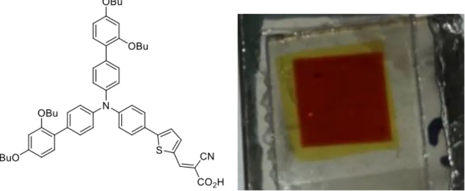
performances of the solar cells were compared with those prepared according to the classical screen-printed technique using dye loading by soaking overnight the electrodes into a dye solution. The solar cells were sensitized with the classical push-pull organic dye D35 using the liquid electrolyte based on iodide/triiodide redox mediator (Figure 1). Interestingly, the digital printing technology enables to shorten the fabrication time of the solar cell, to reach higher efficiencies than those measured with equivalent screen-printed film. Moreover, the fabrication of solar cells on significant surface area (1 cm2) was achieved
underscoring the great potential of this new technique to prepare DSSCs quickly and efficiently.
Figure 1. Structure of the D35 dye and picture of the 1 cm2 DSSC prepared by KELENN digital printing
4
Results and discussion
Scanning Electron Microscopy (SEM)
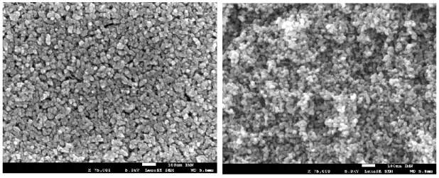
The morphology of the inner structure of the TiO2 layer was investigated by SEM. Figure 2 shows the
cross-sectional SEM images of the TiO2 electrodes mechanically broken with a glass cutter and deposited either
by screen printing or by DMD technology. It can be seen that TiO2 nanoparticles have approximately a
spherical shape and are randomly distributed in both cases. Interestingly, the TiO2 film deposited by DMD
seems to have slightly higher porosity possibly due the absence of the mechanical/shear stress on TiO2
paste during the printing process.
screen printed deposited by DMD
Figure 2. Cross-sectional SEM images of the TiO2 electrodes mechanically broken with a glass cutter
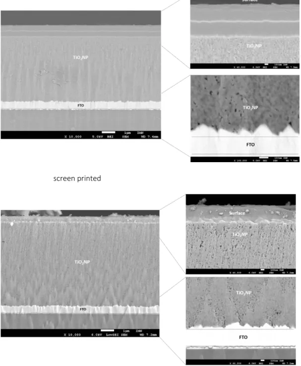
5 screen printed
Deposited by DMD
Figure 3. Cross-sectional images of the electrodes prepared by polishing with an Ar-ion beam and deposited by screen printing (top) or by DMD technology (bottom) with a zoom on the top and the bottom part of the layer.
Figure 3 shows the cross-sectional images of the electrodes prepared by polishing with an Ar-ion beam, with a magnification of the top and the bottom part of the layer. First, the nanocrystalline-TiO2 layer
6
appears very homogeneous, smooth and flat with both printing techniques. Second, the porosity does not seem to be completely homogeneous throughout the film, with a higher porosity on the upper layer and a more tightly packed structure on the bottom (see magnifications). However, with DMD printing, the upper part of the layer appears more porous than with screen printing. This larger open structure obtained by DMD could increase the infiltration of the electrolyte, which then enhance the photocurrent density.
Photovoltaic performances
The digital printed TiO2 films were then used to fabricate DSSC with the D35 sensitizer and using the classical
iodide/triiodide redox mediator (details see experimental part) and the photovoltaic performances were compared with DSSC prepared with conventional screen printed TiO2 nanoparticles. In this study, 0.25 cm2
and 1 cm2 active surfaces were tested. The metrics of the solar cells such a short circuit current density
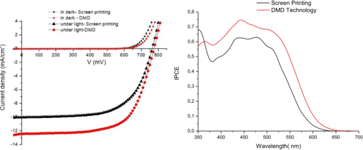
(Jsc), open circuit voltage (Voc), fill factor (ff) and power conversion efficiency (PCE) are gathered in Table 1 (average of about 6 different cells). Typical current/voltage and IPCE spectra are shown in Figure 4.
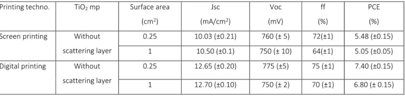
Table 1. Metrics of the solar cells fabricated either by digital printing or screen printing using D35 as sensitizer and illuminated with calibrated AM1.5 (100 mW/cm2).
Printing techno. TiO2 mp Surface area
(cm2) Jsc (mA/cm2) Voc (mV) ff (%) PCE (%) Screen printing Without
scattering layer
0.25 10.03 (±0.21) 760 (± 5) 72(±1) 5.48 (±0.15) 1 10.50 (±0.1) 750 (± 10) 64(±1) 5.05 (±0.05) Digital printing Without
scattering layer
0.25 12.65 (±0.20) 775 (±5) 75 (±1) 7.40 (±0.15) 1 12.70 (±0.10) 750 (± 2) 70 (±1) 6.80 (± 0.15)
The performances of the DSSC fabricated by screen printed method compare very well with previously reported ones[23-25] by other groups with the same dye and for the same surface area and with scattering layer (the highest performances are 6.74%, for 0.25 cm2)[24], indicating that the preparation of the solar
cells was realized according to the good practices. Second, independently of the surface area of the DSSC, the DMD technology gives better performing solar cells than conventional screen-printing technique (Table 1). The champion DSSC made by DMD on 0.25 cm2 surface area gives even 7.7 % efficiency (Jsc= 13.5
mA/cm2, Voc= 760 mV, FF=74%) and 7.1% efficiency on 1 cm2 (Jsc = 12.71 mA/cm2, Voc= 771 mV, FF =71
7
Figure 4. IPCE spectra (left) of the DSSC fabricated by screen printing (black) and by DMD (red) and current/voltage characteristics of the cells (right).
The higher power conversion efficiencies measured with the cells fabricated by DMD are essentially due to a higher short circuit current density (Jsc) and partly due to a higher open circuit voltage (Voc) and fill factor (ff). The origin of these differences are elucidated by IMVS and IMPS measurements and can be explained by a higher charge collection efficiency of the solar cells made by DMD (see below). The amount of dye loading were measured by desorption experiments (see experimental part) and they demonstrate that within experimental error, the quantity of the dyes was very similar for the two printing technology. An average value of 60 nmol/cm2 is in good agreement with a previous report.[25] This indicates that first the
short dying process made by DMD is as efficient as the conventional soaking and second that the higher photocurrent densities measured in DMD prepared DSSC is not due to a higher light harvesting efficiency of the electrodes.
Intensity‑modulated photocurrent spectroscopy (IMPS) and intensity‑modulated photovoltage spectroscopy (IMVS)
To elucidate the origin of the improved performances of DMD DSSCs, IMPS and IMVS measurements [ 26-27] were undertaken to determine the dynamics of the electron transport (τd) and electron lifetime (τe-) in
TiO2 film, and consequently to extract the electron diffusion length (Ln) and the charge collection efficiency
(
η
collect) in each device (DMD technology vs screen printing).350 400 450 500 550 600 650 700 0,0 0,1 0,2 0,3 0,4 0,5 0,6 0,7 0,8 IPC E Wavelength( nm) Screen Printing DMD Technology
8
Figure 5. (a) Electron transport time, (b) electron lifetime, (c) diffusion coefficient, (d) diffusion length, (e) charge collection efficiency, all vs. incident light intensity.
With both
printing
techniques, it can be observed that the electron transport time (τd) decreases whenthe light intensity increases, this is logical since the conductivity is enhanced as the concentration of electrons in TiO2 mesoporous layer is raised due to higher charge injection density [26]. In other words,
de-(a) (b)
(c ) (d)
9
trapping of the injected electrons is increased when electron concentrations are high, because the traps are filled. Interestingly, the effective diffusion coefficient (Dn) of the electron into nanocrystalline TiO2 film
is significantly higher in the DMD printed film than in the screen printed one (Figure 5b). The electron lifetime (τe-) corresponds to the average time that the injected electrons in TiO2 survive before charge
recombination either with the oxidized dye or with triiodide redox mediator in the electrolyte take place. Figure 5b shows that the electron lifetime (τe-) is longer in DMD printed cells than in screen printed DSSC
resulting in longer electron diffusion length (Ln) as shown in Figure 5d. The average electron diffusion length (Ln) and charge collection efficiency (
η
collect) can be calculated according to the equations below:Ln = √𝐷𝑛 × 𝜏2 e‑
η
collect= (1- τ
d/τ
e-)
Inspection of these two parameters, which are plotted in Figures 5d and 4e as a function of light intensity, reveals that the solar cells printed by DMD deliver higher Jsc essentially thanks to a higher charge collection efficiency coming from a longer electron lifetime and a faster electron transport time. This result can be explained by the larger porosity of TiO2 photoelectrode printed with DMD which facilitates the infiltration
of the electrolyte in the structure and most probably by a better passivation of the defects which improves the transport and collection of the electrons.
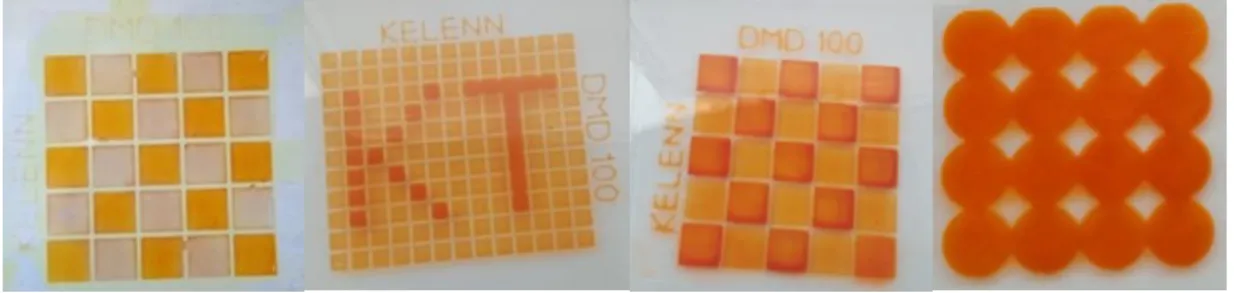
Figure 6. Pictures of some patterns printed on a FTO substrate by DMD.
Finally to demonstrate the versatility of patterns, which can be made by the digital printing
technology (DMD), we have printed different TiO
2patterns and sensitized them (Figure 6).
10
Infrared Spectroscopy study
To elucidate if the adsorption state of the D35 dye differ with the mode of preparation of the TiO2 electrode,
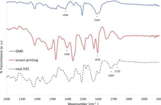
Attenuated Total Reflectance-Fourier Transform Infrared Spectroscopy (ART-FTIR) was used. Toward this goal, the ATR-FTIR spectra of D35 chemisorbed on TiO2 were compared with that of neat D35 dye (Figure
7). Inspection of the ATR-FTIR spectra reveals that they are not superimposable indicating that the environment are not exactly identical on DMD and screen printed film. More specifically, the mode of binding can be analyzed with the position of the wavenumber values associated with the transitions of the carboxylic acid vibrator.
Figure 7. ART-FTIR spectra of neat D35 dye and chemisorbed on TiO2 film prepared either by DMD or screen printing. Asterisks show the wavenumber of the most meaning full signals.
D35 powder shows two strong peaks at 1684 and 1720 cm-1 which are attributed to ν(C=O) stretching peaks
of the carboxylic acid group.[26] When the dye is grafted on the TiO2 surface, the stretching bands of the
carboxyl group disappeared; this indicates the formation of a covalent linkage with TiO2 surface involving
the carbonyl group, excluding thus the monodentate ester like mode. Moreover, the asymmetric stretching mode (as) can be observed at about the same value (1595 cm-1) for both DMD and screen printed films.
On the other hand, the symmetric stretching mode (s) of the carboxylate group can be identified at 1384
cm-1 and 1396 cm-1 for DMD and screen printed electrodes respectively. It was reported that the
11
a tool to diagnose the mode of binding.[27, 28] It is accepted that: (unidentate ester like) > (bridging chelating) > (bidentate). The value for DMD and screen printing electrode is 210 cm-1 and 199 cm-1
respectively, two close and low values, which pleads in favor of a bidendate binding for both materials.[29, 30] In conclusion, the ATR-FTIR study indicates that the environment of the material is not completely similar within DMD and screen printed electrode as also evidenced with the SEM pictures, however, the mode of binding of the D35 dye on the TiO2 surface is very close in both cases and can be assigned to a
bidendate mode. Accordingly, the mode of binding between the two materials is certainly too similar to account for the difference of photovoltaic properties. In addition, let us highlight that the dyeing step is different whether screen printed films (overnight impregnation in a dye bath) or DMD printed films (5 minutes by DMD printing) are used, and this could affect the FTIR spectrum. We precise that all electrodes were thoroughly washed after dyeing to avoid contamination by excessive non-adsorbed dye molecules.
Conclusion
In this work, we have investigated the fabrication of DSSC with a new digital printing technology on 0.25 and 1 cm2 surface areas without scattering layer enabling thus to design transparent solar cells. DMD
technology was used for both the printingof the commercial TiO2 nanoparticles ink and for the sensitization
of the nanocrystalline porous layer. It is important to note that the coating of the TiO2 surface with dye
takes only 10 minutes with the DMD technology, decreasing thus very significantly the duration of the DSSC fabrication process. The photovoltaic performances of solar cells fabricated by DMD are higher than those prepared by conventional screen printing with scattering layer and dyed by soaking the electrodes overnight into a solution of the sensitizer. Moreover, the printing of the TiO2 NPs by DMD can be achieved
with less mechanical strain, resulting thus with a better 3D structuration (porosity and morphology) of TiO2
photoelectrodes enhancing the electron collection efficiency and consequently the efficiency of the solar cells. Finally, this technology simplifies the DSSC fabrication process with reduction of the material consumption and represents an innovative alternative for printing DSSCs devices to conventional screen printing, spray-coating, and inkjet printing technologies.
This work reports the efficiency of a new digital printing technology on the 3D structuration (porosity and morphology) of TiO2 photoelectrodes and his effect on the DSSC overall performances. The
12
scattering layer. In the other side, the DMD technology offers several advantages over screen printing, spray-coating, and inkjet printing. Among them, the printing of the TiO2 NPs without mechanical strain.
Finally, this technology simplifies the DSSC fabrication process with reduces the material consumption and presents an innovative alternative for printing DSSCs devices.
Experimental part
Conductive glass substrates (F-doped SnO2) were purchased from Solaronix (TEC15 and TEC7, sheet
resistance 15 Ω/sq and 7 Ω/sq respectively) were used as the substrates for the photoanodes and counter electrodes, respectively. The substrates were first ultrasonically cleaned in acetone, water with detergent and isopropanol for 30 min, respectively. Then, the substrates were sintered at 500 °C for 30 min. All films have been printed with new printing technology of Digital Materials Deposition. Starting with the printing of diluted solution in ethanol (75 wt% ) of TiO2 blocking layer at 40°C on cleaned FTO at low pressure with
high printing speed. Then, TiO2 pastes (P25) with average particle sizes of about 20 nm were printed with
low printing pressure and speed to obtain a transparent nanocrystalline mesoporous layer of thickness around 6 µm and area 0.25 cm2 and 1 cm2. The photoanodes were sintered at 500°C, 30 min to remove the
additives in the pastes as ethyl cellulose and terpineol. After sintering, the TiO2 films were treated with 40
mM TiCl4 aqueous solution at 70°C for 30 min with DMD process and rinsing with water and ethanol then
sintering again the films. This process healed the defect and increased the contact between the TiO2
nanoparticles. The D35 dye (2 mg/ml in ethanol) was loaded in TiO2 photoanodes with very low printing
speed (0.05 m/min) for 5 min and then washed with ethanol to remove the excess. The TiO2 photoanodes
were assembled with a platinized counter electrode using a hot-melt surlyn film. The redox electrolyte composed of: 30 mM I2, 50 mM Lithium Iodide (LiI), 0.5 M 4-tertbutyl pyridine and 0.6 M
N-propyl-N′-ethyl-methylimidazolium iodide in acetonitrile for the I3−/I− electrolyte, was introduced through a hole drilled in
the back of the counter electrode. Finally, the hole was also sealed with the surlyn film.
DMD100 printing system:
The DMD100 is a printing system based on a x, y, z platform which integrates one patented DMD “Digital Material Deposition” nozzle (with a range size from 80 to 500 µm).The system is described in detail on the patent.[31] The machine presents a vacuum heating flat bed and a printing area of 200 mmx200 mm. The TiO2 ink is similar as that used for screen printing and the electrodes were coated with D35 using an ethanol
solution (2 mg/ml in ethanol) at 30°C (substrate heated with integrated hot-stage) and abundantly washed with EtOH after 5 minutes. The rest of the fabrication follows the same procedure as that described above for screen printed films.
13
Characterizations
The printing technology has a significant impact on the morphology and thickness of the photoanode, dye loading, and electrolyte. Those parameters have a strong impact on DSSC photovoltaic performance. Therefore, some characterization techniques have been used as photocurrent-voltage (J-V) measurement, incident photon to current conversion efficiency (IPCE), scanning electronic microscopic (SEM), (IMVS/IMPS) and UV-vis to investigate the influences of this digital printing technology on the DSSC performance.
The ATR-FTIR spectra were recorded in the ATR mode using a FTIR Bruker Vertex 70 spectrometer.
The current-voltage characteristics were determined by applying an external potential bias to the cell and measuring the photocurrent using a Keithley model 2400 digital source meter. The solar simulator is an Oriel Lamp calibrated to 100 mW/cm². The overall conversion efficiency (PCE) of the photovoltaic cell is calculated from the integral photocurrent density (Jsc), the open-circuit photovoltage (Voc), the fill factor of the cell (FF), and the intensity of the incident photon-to-current conversion efficiency (IPCE) data were collected at the wavelength range of 350−800 nm. The thickness, the morphologies of TiO2 film and sizes
of TiO2 NPs were characterized by using a scanning electron microscope (SEM), the absorption and
desorption of the dye by UV-Visible absorption spectrometer.
Electron transport time and electron lifetimes or recombination were measured by intensity modulated photocurrent spectroscopy (IMPS) and intensity modulated photovoltage spectroscopy (IMVS) respectively. A white-light emitting diode (LED; WLR02) from Zahner controlled by PP211 (Zahner) analyzer was used as the light source for these studies. IMPS and IMVS responses were measured at different bias light intensities. 20, 50, 100, 150, 200, 250 and 300 W/m2. The electron diffusion coefficient (Dn) within
TiO2 film and the electron transport time (τd), this is showed the time for an injected electron to improve
the current density through a TiO2 film, were calculated from the IMPS measurements following the
equations (1) and (2): τd = ½πfmin (IMPS) (1)
Dn = L2 /2.5τ d(2)
where fmin(IMPS) is the characteristic frequency at the minimum of the imaginary component and L is the
thickness of the TiO2 film, which is around 3 μm for all TiO2 films in this work. The calculated τd and Dn
14
information such as the electron lifetime (τe-)and electron diffusion length (Ln)in the TiO2 photoanode and
charge collection rate (ηcc) can be obtained according to the following equations: 3, 4 and (5).
τn = ½πfmin (IMVS) (3)
Ln = (Dnτe-)1/2 (IMVS) (4)
ηcollect = (1- τd/ τe- ) (5)
where fmin(IMVS) is the characteristic frequency at the minimum of the imaginary component.
Dye-Loading measurements
The dyed electrode was soaking for few minutes in about 1 mL of a solution of 0.1 M (CH3)4NOH in
acetonitrile and rinsed with the same solution until having a precise volume of 2 mL. The UV-vis absorption spectrum of the solution was then measured, and the dye loading was estimated from the absorbance. For the calculation, an average of three independent measurements was used.
Acknowledgement
Région des Pays de la Loire is gratefully acknowledged for the financial support of these researches through the program LUMOMAT.
References
[1] B. O'Regan, M. Grätzel, 1991. A low-cost, high-efficiency solar cell based on dye-sensitized colloidal TiO2 films. Nature 353 (6346), 737-740.
[2] A. Hagfeldt, G. Boschloo, L. Sun, L. Kloo, H. Pettersson, 2010. Dye-Sensitized Solar Cells. Chem. Rev. 110 (11), 6595-6663.
[3] L. M. Gonçalves, V. de Zea Bermudez, H. A. Ribeiro, A. M. Mendes, 2008. Dye-sensitized solar cells: A safe bet for the future. Energy Environ. Sci. 1 (6), 655-667.
[4] M. Freitag, J. Teuscher, Y. Saygili, X. Zhang, F. Giordano, P. Liska, J. Hua, S. M. Zakeeruddin, J.-E. Moser, M. Grätzel, A. Hagfeldt, 2017. Dye-sensitized solar cells for efficient power generation under ambient lighting. Nature Photonics 11 372.
[5] A. Mishra, M. K. R. Fischer, P. Bäuerle, 2009. Metal-Free Organic Dyes for Dye-Sensitized Solar Cells: From Structure: Property Relationships to Design Rules. Angew. Chem. Int. Ed. Engl. 48 (14), 2474-2499. [6] Y. Ooyama, Y. Harima, 2012. Photophysical and Electrochemical Properties, and Molecular Structures of Organic Dyes for Dye-Sensitized Solar Cells. ChemPhysChem 13 (18), 4032-4080.
[7] M. Wang, C. Grätzel, S. M. Zakeeruddin, M. Grätzel, 2012. Recent developments in redox electrolytes for dye-sensitized solar cells. Energy Environ. Sci. 5 (11), 9394-9405.
[8] B. Pashaei, H. Shahroosvand, P. Abbasi, 2015. Transition metal complex redox shuttles for dye-sensitized solar cells. RSC Adv. 5 (115), 94814-94848.
15
[9] S. Mathew, A. Yella, P. Gao, R. Humphry-Baker, B. F. E. Curchod, N. Ashari-Astani, I. Tavernelli, U. Rothlisberger, M. K. Nazeeruddin, M. Grätzel, 2014. Dye-sensitized solar cells with 13% efficiency achieved through the molecular engineering of porphyrin sensitizers. Nature Chem. 6 242.
[10] A. Yella, H.-W. Lee, H. N. Tsao, C. Yi, A. K. Chandiran, M. K. Nazeeruddin, E. W.-G. Diau, C.-Y. Yeh, S. M. Zakeeruddin, M. Grätzel, 2011. Porphyrin-Sensitized Solar Cells with Cobalt (II/III)–Based Redox Electrolyte Exceed 12 Percent Efficiency. Science 334 (6056), 629.
[11] K. Kakiage, Y. Aoyama, T. Yano, K. Oya, J.-i. Fujisawa, M. Hanaya, 2015. Highly-efficient dye-sensitized solar cells with collaborative sensitization by silyl-anchor and carboxy-anchor dyes. Chem. Commun. 51 (88), 15894-15897.
[12] P. Wang, L. Yang, H. Wu, Y. Cao, J. Zhang, N. Xu, S. Chen, J.-D. Decoppet, S. M. Zakeeruddin, M. Grätzel, 2018. Stable and Efficient Organic Dye-Sensitized Solar Cell Based on Ionic Liquid Electrolyte. Joule doi.org/10.1016/j.joule.2018.1007.1023.
[13] A. Fakharuddin, R. Jose, T. M. Brown, F. Fabregat-Santiago, J. Bisquert, 2014. A perspective on the production of dye-sensitized solar modules. Energy Environ. Sci. 7 (12), 3952-3981.
[14] M. Saifullah, J. Gwak, J. H. Yun, 2016. Comprehensive review on material requirements, present status, and future prospects for building-integrated semitransparent photovoltaics (BISTPV). J. Mater. Chem.A 4 (22), 8512-8540.
[15] S. H. Kang, S.-H. Choi, M.-S. Kang, J.-Y. Kim, H.-S. Kim, T. Hyeon, Y.-E. Sung, 2008. Nanorod-Based Dye-Sensitized Solar Cells with Improved Charge Collection Efficiency. Adv. Mater. 20 (1), 54-58.
[16] G. K. Mor, K. Shankar, M. Paulose, O. K. Varghese, C. A. Grimes, 2006. Use of Highly-Ordered TiO2 Nanotube Arrays in Dye-Sensitized Solar Cells. Nano Lett. 6 (2), 215-218.
[17] M. Adachi, Y. Murata, J. Takao, J. Jiu, M. Sakamoto, F. Wang, 2004. Highly Efficient Dye-Sensitized Solar Cells with a Titania Thin-Film Electrode Composed of a Network Structure of Single-Crystal-like TiO2 Nanowires Made by the “Oriented Attachment” Mechanism. J. the Am. Chem. Soc. 126 (45), 14943-14949. [18] S. G. Hashmi, M. Özkan, J. Halme, S. M. Zakeeruddin, J. Paltakari, M. Grätzel, P. D. Lund, 2016. Dye-sensitized solar cells with inkjet-printed dyes. Energy Environ. Sci. 9 (7), 2453-2462.
[19] Y. Kunugi, Y. Shimoyama, S. Umezu, 2013. Fabrication of Dye-sensitized Solar Cells Using Electrostatic Inkjet Printing. J. Photopolym. Sci. Tec. 26 (3), 383-385.
[20] S. G. Hashmi, M. Ozkan, J. Halme, K. D. Misic, S. M. Zakeeruddin, J. Paltakari, M. Grätzel, P. D. Lund, 2015. High performance dye-sensitized solar cells with inkjet printed ionic liquid electrolyte. Nano Energy 17 206-215.
[21] M. Özkan, S. G. Hashmi, J. Halme, A. Karakoç, T. Sarikka, J. Paltakari, P. D. Lund, 2017. Inkjet-printed platinum counter electrodes for dye-sensitized solar cells. Organic Electronics 44 159-167.
[22] H.-G. Han, H. C. Weerasinghe, K. Min Kim, J. Soo Kim, Y.-B. Cheng, D. J. Jones, A. B. Holmes, T.-H. Kwon, 2015. Ultrafast Fabrication of Flexible Dye-Sensitized Solar Cells by Ultrasonic Spray-Coating Technology. Sci. Reports 5 14645.
[23] D. P. Hagberg, X. Jiang, E. Gabrielsson, M. Linder, T. Marinado, T. Brinck, A. Hagfeldt, L. Sun, 2009. Symmetric and unsymmetric donor functionalization. comparing structural and spectral benefits of chromophores for dye-sensitized solar cells. J. Mater. Chem. 19 (39), 7232-7238.
[24] X. Jiang, K. M. Karlsson, E. Gabrielsson, E. M. J. Johansson, M. Quintana, M. Karlsson, L. Sun, G. Boschloo, A. Hagfeldt, 2011. Highly Efficient Solid-State Dye-Sensitized Solar Cells Based on Triphenylamine Dyes. Adv. Funct. Mater. 21 (15), 2944-2952.
[25] X. Jiang, T. Marinado, E. Gabrielsson, D. P. Hagberg, L. Sun, A. Hagfeldt, 2010. Structural Modification of Organic Dyes for Efficient Coadsorbent-Free Dye-Sensitized Solar Cells. J. Phys. Chem. C 114 (6), 2799-2805.
[26] A. Abbotto, N. Manfredi, C. Marinzi, F. De Angelis, E. Mosconi, J.-H. Yum, Z. Xianxi, M. K. Nazeeruddin, M. Grätzel, 2009. Di-branched di-anchoring organic dyes for dye-sensitized solar cells. Energy Environ. Sci. 2 (10), 1094-1101.
16
[27] K. S. Finnie, J. R. Bartlett, J. L. Woolfrey, 1998. Vibrational Spectroscopic Study of the Coordination of (2,2'-Bipyridyl-4,4'-dicarboxylic acid)ruthenium(II) Complexes to the Surface of Nanocrystalline Titania. Langmuir 14 (10), 2744-2749.
[28] M. Nara, H. Torii, M. Tasumi, 1996. Correlation between the Vibrational Frequencies of the Carboxylate Group and the Types of Its Coordination to a Metal Ion: An ab Initio Molecular Orbital Study. J. Phys. Chem. 100 (51), 19812-19817.
[29] M. K. Nazeeruddin, R. Humphry-Baker, D. L. Officer, W. M. Campbell, A. K. Burrell, M. Grätzel, 2004. Application of Metalloporphyrins in Nanocrystalline Dye-Sensitized Solar Cells for Conversion of Sunlight into Electricity. Langmuir 20 (15), 6514-6517.
[30] M. Yanagida, T. Yamaguchi, M. Kurashige, K. Hara, R. Katoh, H. Sugihara, H. Arakawa, 2003.
Panchromatic Sensitization of Nanocrystalline TiO2 with
cis-Bis(4-carboxy-2-[2'-(4'-carboxypyridyl)]quinoline)bis(thiocyanato-N)ruthenium(II). Inorg. Chem. 42 (24), 7921-7931.
[31] T. Berthelot, D. Rousseau System for depositing material and associated method. 2019, patent WO2019228821 (A1).