HAL Id: hal-00961422
https://hal-mines-paristech.archives-ouvertes.fr/hal-00961422
Submitted on 1 Apr 2014HAL is a multi-disciplinary open access archive for the deposit and dissemination of sci-entific research documents, whether they are pub-lished or not. The documents may come from teaching and research institutions in France or abroad, or from public or private research centers.
L’archive ouverte pluridisciplinaire HAL, est destinée au dépôt et à la diffusion de documents scientifiques de niveau recherche, publiés ou non, émanant des établissements d’enseignement et de recherche français ou étrangers, des laboratoires publics ou privés.
An Overview of Molten Polymer Drawing Instabilities
Yves Demay, Jean-François Agassant
To cite this version:
Yves Demay, Jean-François Agassant. An Overview of Molten Polymer Drawing Instabilities. Inter-national Polymer Processing, 2014, 29 (1), pp.128-139. �10.3139/217.2832�. �hal-00961422�
An overview of molten polymer drawing instabilities
Yves Demay1 Jean-Francois Agassant2
1 Université de Nice Sophia-Antipolis, Laboratoire Jean Alexandre Dieudonné, UMR CNRS 6621, 06108 Nice Cedex 2, France
2 Mines-Paristech, Centre de Mise Forme des Matériaux, UMR 7635 CNRS, 06904 Sophia Antipolis, France
Abstract
Drawing instabilities and rupture are a serious limitation in polymer fibre and film processing. Onset of these defects depends on the processing conditions, on heat transfer, and on the rheology of the polymer even if some may be encountered for Newtonian fluids. The main part of this paper is devoted to the different forms of the draw resonance instability encountered in fibre spinning, cast-film and film blowing. The time dependent equations are presented for the simplified situation of constant width cast-film. Results of the two possible modelling strategies, linear stability analysis and direct simulation, applied to the different fibre and film processes are discussed.
1. Introduction
Numerous polymer processes (fibre spinning, cast film or film blowing) involve a stretching step after the initial extrusion step. Drawing instability (draw resonance) is a typical defect encountered during stretching in air. The existence of an air-polymer interface allows the onset of a periodic instability leading to very large variations of thickness, width and diameter. This paper deals with the different forms of the drawing instabilities encountered in classical processes such as fibre spinning, cast-film and blown film.
In fibre spinning, a polymer (generally Polyester or Polyamide) is first melted by heat transfer and viscous dissipation in a screw/barrel device and then forced in a spinning pack consisting of a metal plaque with several (hundred) holes (typical diameter between 0.3 and 1 mm). The several hundred filaments emerging from the spinning pack are then stretched in order to obtain the final required diameter of textile filaments (several ten micrometers). This requires high draw ratios (ratio between the drawing wheel velocity and the die exit velocity), under severe cooling conditions (air jet or water bath) in order to obtain a solidified spun fibre at the drawing wheel. In addition, stretching the filament allows the development of appropriate mechanical properties. The stretching distance may vary from a few centimeters for water bath cooling systems to several meters for classical air jet cooling.
There are two families of processes for polymer film production:
• In the cast-film process, the polymer is melted in an extruder and forced in a coat hanger flat die to produce an initial web (1 or 2 m in width, 1 mm in thickness) which needs then to be stretched between the die and a chill roll in order to obtain the required film thickness (several ten microns is required for packaging applications).
• In the blown film process, the molten polymer is forced within a tube die. This tube is then simultaneously stretched in the vertical direction by nip rolls, inflated by an internal pressure and cooled by external air rings. A more precise description of these processes may be found in Agassant et al. (1996).
Let us note that both diameter of the holes of a spinning pack and final gap of a coat-hanger or tube die need to be sufficiently large in order to limit the required extrusion pressure. It leads naturally to an important stretching rate (Draw ratio Dr). In fibre and film production, two kinds of defects may be observed at high draw ratios, periodic fluctuations of the diameter (fiber spinning) or of both the film thickness and width (cast-film) or the film thickness and the bubble diameter (film blowing) but also filament or web rupture. All these phenomena depend on the stretching distance, the cooling conditions and the rheology of the molten polymer, but it is important to mention that some of these instabilities may be encountered even for Newtonian fluids (glass fibre processing for example).These instabilities are the more drastic limitation for process productivity, and at present it is a real challenge to master and then to postpone their occurrence.
Several extensive review papers have been devoted to the experimental and theoretical analyses of these instabilities : Co (2005) for cast film, Jung and Hyun ( 2005, 2006) for fibre spinning and film blowing.
In the present paper, various drawing instability experiments performed at CEMEF-Mines ParisTech or in cooperation with Ecole Polytechnique-Montreal are presented in the next paragraph. The time dependent stretching equations for the constant width cast film process are presented as a reference case in the third paragraph. The different strategies used to explain draw resonance instabilities as well as fibre or web breakage at high draw ratios are discussed in the last paragraphs.
2. Experiments
Most of the published experiments have been devoted to filament stretching instabilities. The basic experiment may be done with purely viscous (corn syrup for example, Chang and Denn, 1979) or viscoelastic (molten polymers) fluids (Kase, 1974; Ishihara and Kase, 1975; Demay, 1983). The experiments consist in extruding a fluid from a capillary die at a constant flow rate (velocityu ) and increasing progressively the take-up velocity0 u imposed at a short L distance from the die, which corresponds to a quasi-isothermal situation. The fiber diameter is continuously recorded along the stretching path and after solidification (for molten polymers). Stretching step intensity is evaluated by the so called Draw ratio (a dimensionless number) defined as DruL/u0. At low Draw ratio, the stretching flow is stable which means that the filament diameter is constant in time and any perturbation decreases and goes to zero with time (figure 1a). When increasing the Draw ratio above a critical value Dr*which is of the order of magnitude of one to several tens, the flow becomes unstable: This means that a sustained periodic diameter fluctuation develops (figure 1b). It appears just at the die exit and then propagates till the extremity of the stretching path (Hyun, 1999). When the Draw ratio is increased again, the amplitude of the periodic instabilities increases till very large values (a ratio of 10 between the maximum and the minimum diameter may be reached) (figure 1c). Ghiljels and Ente (1980) identified directly the occurrence of these instabilities by recording continuously the stretching force which is obviously very small (of the order of several milli-Newton). When increasing the stretching distance, the process becomes progressively non isothermal and the critical Draw ratio Dr*increases too (Blyler and Gieniewski, 1980; Gupta and Drechsel, 1981; Demay, 1983). When the stretching distance L is sufficiently large, more complex phenomena occur as stress induced crystallization involving changes in the temperature field. This may result in a strong necking phenomenon in the crystallization zone which prevents from the drawing instability development (Shin et al., 2006; Kohler and McHugh, 2008). When stretching polymers of increasing elasticity in quasi-isothermal conditions, the critical Draw ratio remains first more or less constant and then the periodic instability disappears and frequent filament breakages are then observed (Chang and Denn,
1979). Spinning experiments have been performed with Polyesters of various macromolecular architecture, which results in different viscoelastic properties (White and Yamane, 1985). As pointed out by Demay and Agassant (1985) different instabilities may be observed depending on the viscoelastic properties (figure 2). The Deborah number De weights the mean relaxation time of the polymer to a characteristic time of the processL u . For polyester A and C, / 0 whatever the value of the extrusion velocityu , the spinning process becomes unstable for 0 critical draw ratios Dr*between 15 and 20. For Polyester B, the periodic instability is never encountered, but filament breakage. The behaviour of polyester D is in-between the preceding ones: periodic instabilities at low extrusion velocity (low Deborah number) and filament breakage at high extrusion velocity (high Deborah number).
In the cast-film process, both thickness and width periodic fluctuations are observed above a critical Draw ratio of the same order of magnitude as in fibre spinning. But the phenomenon is more complex because film stretching induces also width reduction (called neck-in) and related lateral over-thicknesses (called dog-bone defect). This is the reason why very few experimental results are available. Barq et al. (1990) performed careful and tedious width and thickness fluctuation measurements (in the central part of a PET film and along the edges) on very long distances (figure 3). They point out periodic fluctuations with the same period for width and thickness. The maximum thickness in the central part of the film corresponds more or less to the minimum width, but the two periodic fluctuations do not balance with another which means that the flow rate at take-up is also a function of time. Shin et al. (2007a) recorded the film thickness in the central part of HDPE and LDPE films as a function of time. Agassant et al. (2006) were able to identify the occurrence of the cast film instability by recording continuously the stretching force as a function of time for various LLDPE films (figure 4). This is easier than in fibre spinning because the stretching force is much more important (several Newtons). Bourrigaud et al. (2006) showed for a series of LDPE of various viscoelastic properties that web rupture may be observed at a Draw ratio which decreases when the Deborah number increases (figure 5).
In film blowing, stretching intensity is evaluated by the Draw ratio but also by the Blow-up ratio (BurRL/R0, R is the final bubble radius and L R the tube die radius). The 0 same type of phenomenon as in cast-film may be expected, that means a periodic fluctuation of thickness and diameter (figure 6) (Kanai and White, 1984; Minoshima and White, 1986; Ghaned-Fard et al., 1996; Laffargue et al., 2002, 2010). In fact a non-axisymmetric instability may also be observed, which corresponds to a helical shape of the bubble between the die exit and the film freezing line (figure 7). Ghaned-Fard et al. (1996) developed a sophisticated optical device to capture quantitatively simultaneously the diameter of the bubble and the location of its centre at each position between the die exit and the freezing line. Figure 8 shows, for a Blow-up ratio (Bur) of 2.75, that the bubble radius remains constant for a Draw ratio (Dr) of 9.4. When increasing Dr to 9.9, pronounced periodic radius variations are observed. When decreasing again Dr to 9.4, the bubble radius stabilizes. At the same time, the centre of the bubble remains stable. On the contrary, for a Bur of 3.25, the bubble radius remains constant when increasing Dr from 6.6 to 7.1, but at the same time the centre of the bubble rotates (figure 9) in an horizontal plane giving a helical shape to the bubble. Laffargue et al. (2010) performed film blowing experiments on various extrusion lines but with the same LLDPE. They point out the existence of a stability hill splitting stable and unstable blowing conditions (for both axisymmetric and helical instabilities (figure 10)).
The physics which governs the appearance of the drawing instability may be explained qualitatively. Having in mind that the requirement of the process is to accelerate the molten polymer from the die exit (velocityu ) to the take up wheel (velocity0 u ), one may consider L that this may be done in two different ways:
- at low Draw ratio the velocity increases progressively from x=0 to x=L, the flow is steady and the dissipated energy is mainly due to stretching,
- at higher Draw ratio, a time dependant flow will require less energy than the steady one: first flow packets are formed at die exit and then these packets are accelerated from
0
u to u at low deformation rate and then at low energy expense because inertia is L negligible.
Models will be built to account for the onset and the development of the draw resonance instability but “without necessarily revealing the fundamental cause of the instability itself” (Hyun, 1999). The first step consists in obtaining a time dependant model for the stretching flow. A web with an initial thickness e0 1mm is stretched between a die and a chill-roll (or a water bath) on a distance L10cm. The width W of the web is supposed to be constant (the neck-in phenomenon is neglected) and the velocity u and the current thickness e are assumed to be uniform in each cross-section (figure 11). As the aspect ratio ( e0/L) of the stretching flow is small, it is possible to build a simple but realistic membrane model (Yeow, 1976; Antukar and Co, 1988 ; Barq et al., 1990, 1994). Let us note x the distance to the extrusion die (0<x<L) and t the time.
- Mass conservation writes: ( )e (eu) 0
t x
(1)
- Assuming a Newtonian behaviour (viscosity ) and neglecting the shear terms in front of the elongation terms leads to the Trouton equation for film stretching:
xx 4 du dx
(2) - The force balance writes, neglecting mass forces and inertia:
F eWxx= constant (3) - Boundary conditions imposed by the process are the following:
u(t; 0) =u0 ; u(t; L) =uL ; e(t; 0) = e0 (4) Let us recall that u0 and uL are respectively velocity at die exit and take up. It is to notice that the final thickness is imposed only if the process is steady. It is then possible (and in this case very easy) to compute a steady (not time dependant) flow. It writes:
( ) 0( ) x L u x u Dr ( ) 0( ) x L e x e Dr (5) The key point is to know if this steady flow is stable (really observed in the experiments). It means that a small perturbation of the steady state solution (5) introduced in equations [1-4] decreases with time up to vanish. Two different strategies (giving in fact complementary information) may be used.
- The first one is direct numerical simulation. Equations [1-4] are numerically solved according to variables t and x using a suited time and space scheme. The initial data at t = 0 is the stationary solution slightly disturbed. If this initial perturbation decreases and goes to zero, the process is stable. If the initial perturbation develops, the process is unstable. This method is relatively costly because of the time and space discretization
but is efficient to determine the periodic flow far away from transition (at relatively high Draw ratio). Some examples will be presented in the next paragraph.
- The other one is linear stability analysis which allows determining rapidly the critical parameters (critical draw ratio) for onset of the instability. In this case a perturbed solution of the following form is introduced.
u x( )u x( )exp(t u x) ( )ˆ e x( )e x( )exp(t e x) ( )ˆ (6) In this equation, is an eigenvalue (a complex number) and u xˆ( )and e xˆ( )are eigenfunctions. Linearized equations are obtained by substituting the perturbed values of velocity and thickness (equation 6) in equations [1-4] and neglecting terms of order 2 according to u x and ˆ( ) e x . This system allows computing the dominant eigenvalues ˆ( ) (there are theoretically an infinite number of eigenvalues) and associated eigenfunctions. The steady flow is stable if all the eigenvalues have a negative real part. The steady flow becomes unstable if the real part of a pair of complex conjugate dominant eigenvalues vanishes for Dr=Dr* ( ) and becomes positive for Dr > Dr*. This is the general framework of the i Hopf bifurcation theory. For Dr > Dr* the steady flow becomes unstable and generally a stable periodic flow appears. At transition between stable and unstable flow, the period is determined by the corresponding imaginary part of the eigenvalue (T2 / ). This simple model predicts the onset of the instability for a critical Draw ratio Dr*=20.2 and it will be seen in the following that mechanical and thermal processing conditions as well as polymer rheology can influence largely the value of the critical Draw ratio. However this order of magnitude is in good agreement with experimental measurements.
These mathematical approaches described in a simple case have to be extended to account for more realistic situations:
- Geometry and kinematics: neck-in and varying thickness for the cast film process, axisymmetric situation in fibre spinning, non-uniform velocity profile through the thickness when the stretching distance decreases (the aspect ratio is no more small), non-axisymmetric bubble shape to account for the helical defect in film blowing.
- Heat transfer: as soon as the stretching distance is significant, the polymer temperature decreases and the energy equation as well as the temperature dependence of the viscosity have to be accounted for.
- Constitutive equations: The Newtonian behaviour is a crude approximation for polymer stretching. Viscoelastic constitutive equations need to be accounted for and, surprisingly, even an upper-convected Maxwell constitutive equation provides qualitative results.
Jung and Hyun (2005) proposed a more physical understanding of the development of these drawing instabilities based on different kinematic waves travelling along the stretching line.
In the following sections, the stability of the different stretching processes will be studied, taking progressively into account heat transfer, enriched kinematics and constitutive equations.
4. Cast-film process 4.1. Influence of cooling
In the cast-film process, the stretching distance is generally as small as possible in order to limit neck-in and the related dog bone defect (Silagy, 1996) and so temperature remains more or less uniform. For some coating application, this stretching distance is more important (for geometrical constraints) and temperature decreases, but crystallization temperature is generally not reached before the contact point with the chill roll. The temperature balance equation writes: ( ) c( ) T T ce u h T T t x (7)
In this equation denotes the polymer density (function of the temperature), c the heat capacity, T the mean temperature in the thickness, (which is consistent with the shell approximation for the kinematics), T the surrounding temperature (a complex compromise between air and tool temperature) and h the heat transfer convection coefficient (free or c forced convection depending on the web velocity). System of equations [1-4, 7] is completed to account for the influence of temperature on viscosity. Using the same perturbation procedure as in the preceding paragraph, the stability of the process is determined as a function of the Stanton number St which represents a non-dimensional value of the heat transfer coefficient. It is found that cooling stabilizes largely the process up to conditions stable for any values of the draw ratio at large enough values of the Stanton number.
4.2. Influence of the neck-in phenomenon
In order to account for the width reduction the thin shell membrane model is enriched in two successive steps:
- First, both thickness and velocity in the stretching direction u(x) are supposed to remain constant through the width of the web W(x). The velocity component v(x,y) in the transverse direction has to be introduced but the continuity equation allows to express it as a function of x: v x y( , ) yf x( ) . The linear stability analysis allows computing the value of the critical Draw ratio Dr* as a function of the shape factor of the film A=L/W (Silagy et al., 1996, 1998). The case A=0, corresponds to a very short stretching distance and in this situation the constant width cast-film analysis developed in the preceding paragraph is valid (the critical draw-ratio is Dr*=20.2). Increasing A value means increasing the drawing distance and the critical Draw ratio Dr* increases too. For example, for A=1, the value of the critical Draw ratio is increased by 50% as compared to A=0 (figure 12).
- The membrane model is then enriched to capture both development of the dog bone defect and neck-in by considering thickness and mean velocities in stretching and transverse directions to be functions of x and y (e(x,y), u(x,y) and v(x,y)). Direct numerical simulation was used by Silagy et al., (1998). Figure 13 shows the thickness as a function of time for increasing values of the Draw ratio after introducing at t=0 a small arbitrary perturbation of the steady flow (A= 0.5). For Dr<21, the initial perturbation vanishes rapidly. For Dr=27, a small, but non periodic, perturbation is observed. For Dr=31.5 a periodic well marked perturbation develops and grows slowly in amplitude. It becomes very important for Dr=36 and saturation of the amplitude is rapidly reached (with a ratio of eight between the maximum and the minimum thickness). As compared to the linear stability analysis, the border between stable and unstable drawing regime is less precisely defined but it allows predicting the shape of the film in unstable conditions: figure 14 shows that width and thickness fluctuations (in the central part and at the periphery of the film) as a function of time are in phase opposition which is in agreement with experiments
of figure 3. Figure 12 compares the 2D direct numerical stability simulation and the 1D linear stability analysis. The development of the dog bone defect in the 2D model could contribute to increase the stability of the process: for A=1, the critical Draw ratio is around 40 for the 2D model as it was around 30 for the 1D model.
4.3 : Validity of the membrane model : 2D transverse simulation
The membrane model previously described assumes a constant velocity profile through the thickness. This hypothesis is clearly valid in the stretching part of the flow i.e at a distance x larger than one or several thickness of the die gap. To describe precisely rearrangement from a shear flow in the slit die (the extremity of the coat hanger die) to a stretching flow, it is necessary to use a 2D model in the (x, z) plane (coordinates of figure 11). For sake of simplicity it is assumed as previously that the fluid has a Newtonian behaviour and that mass forces, inertia and surface tension are neglected. A 2D Stokes problem has to be solved on an unknown domain and determination of the polymer-air interface is a part of the solution. It is a so called free interface problem and two strategies are then possible:
- If a surface tracking method is used the kinematic and dynamic interface boundary conditions are explicitly enforced. The Stokes problem is solved on a computation domain which is restricted to the polymer flow. Interface with air is determined by successive iterations (by adjusting the position of the nodes on the interface) to satisfy the kinematic interface equation. This first strategy is relatively precise but unable to describe transient evolution of the interface. The linear stability method is then used to predict onset of draw resonance (Souli et al.,1993).
- If a surface capturing method is used the computation domain is extended to the neighbourhoods of the air interface and the Stokes problem is coupled with a transport equation. Classical approaches are the level set and the Volume of Fluid method. A complex mesh refinement is required in the vicinity of the interface but it allows capturing severe topological changes of the flow domain. Then a time and space numerical scheme (direct numerical simulation) is used to predict onset of draw resonance. In this case the periodic solution is obtained even for high values of the Draw ratio (Fortin et al.,1995).
If this represents an important increase in the computation complexity, it brings also important precision illustrated in the following by two examples obtained at a Draw ratio Dr = 18 using the tracking method and modelling both extrusion and stretching.
- Figure 15a presents the mesh and the flow domain computed for an aspect ratio = 1/15. A significant swelling at the die exit is observed as it would be expected that drawing will eliminate die swell. This explains that the experimental critical Draw ratios are always less than the theoretical ones (figure 2). The dominant eigenvalue ( =-0.084 + i11.99) is very close to the limit of stability (real ( ) =0). It is interesting to notice that this critical Draw ratio Dr* =18 accounting for the transition between the slit die and the stretching flow is near the critical Draw ratio of the 1D membrane model Dr* = 20.2 .
- Figure 15b presents the mesh and the flow domain computed for an aspect ratio =1/5.There is no more visible swelling in this case and the flow is more stable as the real part of the eigenvalue ( =-0.38 + i12.149) is much more negative. It points out that 2D simulation is required to determine stability conditions when the stretching distance decreases. Figure 16 illustrates the variation of the real part of the dominant eigenvalues as a function of the stretching distance.
4.4. Influence of the rheology
As a first approach, the viscoelastic behaviour of the polymer may be introduced through the simple upper-convected Maxwell (UCM) model which writes for the constant width model: ( xx xx 2 ) 2 xx xx du du µ u t x dx dx (8a) ( zz zz 2 ) 2 zz zz du du µ u t x dx dx (8b) µ is the relaxation time and and xx are the extra-stress components of the stress tensor. zz The thin shell approximation writes:
xx xx (8c) zz Solving stationary equations is not possible for every value of the Draw ratio Dr and the Deborah number De (it is the non-dimensional value of the relaxation time µ : u0
De L
).
This has been mentioned by Denn et al. (1975) and Antukar and Co (1988) who pointed out the existence of an unattainable drawing region in the vicinity of which the stretching force increases by several orders of magnitude (figure 17) and this is related to the dramatic increase of the elongation viscosity observed for the upper-convected Maxwell model. Even the use of more realistic viscoelastic models, limiting the increase of the elongation viscosity, leads to non-physical values of the stretching force (Silagy et al., 1998). This could explain web breakage experimentally observed by Bourrigaud et al. (2006) for a collection of LDPE of varying viscoelasticity (figure 5). It is interesting to notice that the shape of the experimental film stretching limit is similar to the theoretical one, even if the experimental Draw ratios at rupture are more important than the ones theoretically predicted with the upper-convected Maxwell model.
For stability analysis, equations [1, 3, 8] are linearized in the same way as in the preceding paragraph. Figure 18 discriminates stable and unstable drawing conditions in the (Dr, De) plane for different values of the film shape factor A. At low Deborah number, which corresponds to a weak elasticity of the polymer, a low extrusion velocity or a long stretching distance, the critical draw ratio Dr* is slightly dependent on the film shape factor A. Above a critical Deborah number De*, which decreases markedly when the film shape factor increases, the periodic instability disappears. It is note-worthy to observe another stable region, for small Deborah numbers, at high draw ratios. This is not a mathematical artifact and an US patent has been applied (Chambon et al., 1998) to draw films in these super-stable conditions. Silagy et al. (1998) and Kim et al. (2005) coupled the UCM model with a 2D membrane model accounting for width and thickness reduction. Kim et al. (2005) computed the transient thickness and width responses to small perturbations using a time-space numerical scheme. Shin et al. (2007a) developed the same approach but with a Phan-Thien Tanner model which limits the increase of the elongation viscosity.
These models lead to the following interesting conclusions about the stability of the cast film process.
- For short stretching distances, periodic thickness and width instabilities may be observed for a Draw ratio higher than a critical value around 20.
- Increasing the stretching distance will stabilize the process, due to both neck-in and cooling phenomena, but then the dog bone defect develops which necessitates trimming lateral sides of the film.
- Curiously, decreasing the stretching length to a distance of the order of magnitude of the die gap dimension will also stabilize the process.
- Using polymers of increasing viscoelasticity only slightly affects the web stability until a critical value above which the process becomes much more stable. The development of periodic instabilities is then no more a limitation, but web rupture may be observed. Let us point out that swelling at die exit will increase too and it is expected that it modifies the critical Draw ratio computed from the membrane model. Accounting for the coupled flow in the die and along the stretching distance for a viscoelastic fluid remains a challenge for a viscoelastic behavior as it is difficult in this case to deal with the stress singularity at die exit.
5. Fibre spinning
The basic equations of the fibre spinning process are essentially the same as for the constant width cast-film process. As a consequence the critical Draw ratio in isothermal Newtonian fibre spinning is equivalent (Dr*=20.2) (Kase and Matsuo, 1965; Pearson and Matovich, 1969; Kase, 1974; Ishihara and Kase, 1975; Fischer and Denn, 1975; Demay and Agassant, 1982) and this is in agreement with experiments presented in paragraph 2.
In high velocity fibre spinning process (up to 5000 m/mn for Polyamide or Polyester) the stretching distance is important (several meters) and additional air-jet is applied in order to cool the filament which makes the process highly non-isothermal (Kase and Matsuo, 1965). The first linear stability analysis show (Shah and Pearson, 1972; Demay and Agassant, 1982) that the critical Draw ratio increases rapidly with the non-dimensional heat transfer coefficient when neglecting crystallization. This is in agreement with PET experiments (figure 19).
When introducing a viscoelastic UCM constitutive equation, the same phenomena are obtained as in the constant width cast-film situation (Fisher and Denn, 1976; Demay, 1983): an unstable region with the development of periodic instabilities at moderate Deborah numbers and intermediate Draw ratios, and an unattainable region at high Deborah number and high Draw ratios where the stretching force becomes infinite which would explain filament breakage. This is consistent with experiments (figure 2). More realistic viscoelastic models have been introduced by Lee et al. (2001) as Jung et al. (1999) coupled the UCM model and heat transfer. Lee et al. (2005), Shin et al. (2006) as well as Kohler and McHugh (2007, 2008) introduced stress induced crystallization and the corresponding crystallization energy in the temperature balance equation. Kohler and McHugh (2007, 2008) used a linear stability analysis and both Giesekus and Pom-Pom viscoelastic models to describe the response of the spinning line to a small variation of a spinning parameter in stable processing conditions. Interestingly, Shin et al. (2006) followed the real part of the dominant eigenvalue as a function of the take-up speed and pointed out the stabilizing effect of the necking phenomenon.
The following conclusions may be drawn for the fibre spinning process.
- As soon as the stretching distance and the cooling conditions are important, the periodic instability is not a true limitation.
- When increasing the extrusion velocity or (and) the relaxation time at constant Draw ratio, the stretching force increases dramatically which induces breakage.
- The rheology of the polymer during the crystallization step, especially at the high cooling rates encountered in the process, is not well mastered and this is the main limitation of the existing models (Jarecki and Ziabicki, 2004).
4.3. Film Blowing
At a first glance, one may consider that film blowing is simply a non-isothermal rolled up cast-film process, with a uniform thickness and with an increasing width instead of a width reduction (neck-in). Heat transfer would stabilize the process and viscoelasticity would cause web breakage at high Draw ratios. However experiments listed in section 2 showed unexpected phenomena: the existence of axisymmetric instabilities (which after unrolling correspond to both thickness and width variations) but also of non-axisymmetric instabilities. The reason is that the molten polymer tube is subjected to a Draw ratio, but also to a pressure differential (between the air inside the bubble and the atmospheric pressure) which induces a Blow-up ratio (Bur) and that is the combination of these two orthogonal drawings which makes the stability of the process much more complex.
It is surprising that modeling such a widely used process presents so many mathematical difficulties. All models use a membrane approximation leading to a system of partial differential equations according to the drawing distance z and time t. Computation of the steady state solution remains a numerical challenge for some operating conditions: both non existence or multiplicity of numerical solutions are found according to processing parameters values. The early steady state Newtonian isothermal model (Pearson and Petrie, 1970) has been extended to account for non-isothermal effects (Han and Park, 1975) coupled with crystallization (Kanai and White, 1984, 1985). Introducing an isothermal Maxwell (UCM) viscoelastic constitutive equation may lead to multiple solutions depending on the boundary conditions (Cain and Denn, 1988). Andre et al. (1998) studied the Maxwell non-isothermal film blowing process and pointed also out that no or multiple solutions may be obtained depending on the processing conditions. Hyun et al. (2004) introduced a viscoelastic Phan-Thien Tanner (PTT) non isothermal model. Doufas and McHugh (2001) and Pirkle and Braatz (2010) introduced flow induced crystallization with a two-phase model.
If the time dependent equations for the axisymmetric model were early introduced, the transient studies remain difficult because the boundary condition inside the bubble is not clear (fixed air volume or fixed pressure as a function of time). Yeow (1976), Cain and Denn (1988), Yoon and Park (1999) assume a Newtonian isothermal behavior and developed the same kind of linear stability analysis as in fibre spinning or cast film. They point out the big influence of the boundary condition inside the bubble on the instability onset. Pirkle and Braatz (2003) performed time dependent simulations and obtained the steady state result by integrating transient equations for a sufficient long time. Shin et al. (2007b) studied the stability of a PTT non-isothermal model as Henrichsen and McHugh (2007) used a viscoelastic Giesekus constitutive equation and compared there results to LDPE film blowing experiments. Both used a constant air volume condition inside the bubble.
All these models are only focused on the axisymmetric instabilities. Following Housiasdas and Tsamopoulos (1998), Laffargue et al. (2010) wrote and solved the film blowing equations in the frame affixed to the die geometry. This leads to complex developments which are detailed in Laffargue (2003) and Laffargue et al. (2010) but this allows capturing both axisymmetric and helical instabilities. Each variable (bubble radius,
bubble thickness, velocity, vertical stress, pressure, temperature…) is expressed as the sum of the stationary solution and a perturbation which writes:
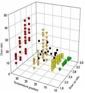
X t z( , , ) X t z( , ) exp( tim) ( )X zˆ (9) In this equation X corresponds to any geometrical, kinematics, stress or temperature variable listed before. X is the corresponding stationary solution and ˆX is an eigenfunction. The complex number is as previously an eigenvalue describing growth or decay of perturbations. The positive integer m is the azimuthal wave number: m=0 corresponds to an axisymmetric instability as m=1 corresponds to a helical instability (higher order instabilities (m>1) have not been investigated yet). Figure 20 shows the real part of the most important eigenvalue as a function of the Draw ratio for m=0 (axisymmetric case) and for m=1 (helical case) when the Blow-up ratio (Bur) is 2. For m=0, the eigenvalue becomes positive for a Draw ratio of 29, as the eigenvalue corresponding to m=1 is negative. This means that the axisymmetric instability will be activated. On the contrary, figure 21 shows the real part of the eigenvalue corresponding to m=1 as a function of Bur for a fixed Dr=6. The real part of the eigenvalue remains negative till Bur=3.5 and then becomes positive. In that blowing situation the eigenvalue corresponding to m=0 is negative which means that the helical instability will be activated. Figure 22 summarizes the results in the (Dr, Bur) plane: When varying the temperature gradient along the bubble (which means varying the air flow in the surrounding air ring) it is possible to build an envelope delimiting stable and unstable film blowing conditions (figure 23). This figure allows drawing interesting conclusions for the stability of the film blowing process:
- For given heat transfer conditions, increasing the Blow-up ratio stabilizes first the process (which means it is possible to impose more important Draw ratios and so to decrease significantly the film thickness in stable conditions) as it was likely to speculate the contrary.
- Above a critical Bur, Dr needs to decrease in order to remain in stable conditions. - This “stability hill” is less pronounced when the temperature gradient (the air flow in
the surrounding ring) increases.
Recently Lee et al. (2011a) showed that crystallization may stabilize the film blowing process as in fibre spinning. Using a constant blowing pressure inside the bubble in a viscoelastic non-isothermal model, Lee et al. (2011b) showed very different results than with the classical constant air volume boundary conditions.
5. Conclusions
Instabilities are encountered in most polymer forming processes. In extrusion or co-extrusion, these instabilities are directly linked to the viscoelastic behaviour of the polymer. In fibre and film stretching processes, drawing instabilities are present even for purely Newtonian fluids which means that their occurrence is, at the first order, governed by dissipation minimization mechanisms. However heat transfer and viscoelasticity will influence the onset and the development of the defect, and even suppress it. In shear dominant flows, as encountered in extrusion dies, sophisticated constitutive equations have to be used in order to account for instabilities. In fluid stretching operations, even a simple constitutive equation, as for example the upper-convected Maxwell model, is able to capture the main features. The reason is that in confined flows, a wide distribution of shear rates is present, as
in fluid stretching the elongation rates remain within a narrow range which induces activation of a dominant relaxation time.
References
Agassant, J. F., Avenas, P., Sergent, J.Ph., Vergnes, B., Vincent, M., “La Mise en Forme des Matières plastiques”, Techniques et Documentation (Lavoisier), Paris (1996).
Agassant, J.F., Bouamra, R., Peiti, C., Haudin J.M., “Cast film extrusion, geometrical defects and stability”, Proceedings of the Polymer Processing Society Meeting, Yamagata (Japan) (2006).
Andre, J.M., Agassant, J.F., Demay, Y., Haudin, J.M., Monasse, B., “Numerical modelling of the polymer film blowing process”, Int. J. of Forming Processes, 1, 197-210, (1998). Anturkar, N.R., Co, A., “Draw resonance in film casting of viscoelastic fluids: a linear
stability analysis”, J. Non-Newt. Fluid Mech., 28, 287-307, (1988).
Barq, P., Haudin, J.M., Agassant, J.F., Roth, H., Bourgin, P., “Instability phenomena in film casting process. Experimental and numerical approaches”, Intern. Polym. Proc., 5, 264-271, (1990).
Barq, P., Haudin, J.M., Agassant, J.F., Bourgin, P., “Stationary and dynamic analysis of film casting process, Intern. Polym. Proc., 9, 350- 358, (1994).
Blyler, L.L., Gieniewski, C., “Melt spinning and draw resonance of a poly(-methyl styrene/silicone) block copolymer”, Polym. Eng. Sci., 28, 140-148, (1980).
Bourrigaud, S., Marin, G., Dabas, V., Dupuy, C., Silagy, D., “The Draw ratio-Deborah number diagram: A useful tool for coating applications”, Polym. Eng. Sci., 46, 372-380, (2006).
Cain, J.J., Denn, M.M., “Multiplicities and instabilities in film blowing”, Polym. Eng. Sci., 28, 1527-1541, (1988).
Chambon, F., Silagy, D., Demay, Y., Agassant, J.F., Ohlsson, S., “A method to reduce draw resonance”, Patent 94P 6B 004/006, (1998).
Chang, J.C., Denn, M.M. “An experimental study of isothermal spinning of Newtonian and viscoelastic liquid”, J. Non-Newt.Fluid Mech., 5, 369-385, (1979).
Co, A., “Draw resonnance in film casting”, Chap.10 in Polymer Processing Instabilities: Control and Understanding, edited by Hatzikiriakos, S.V. and Migler, K.B., Marcel Dekker, New York, (2005).
Demay, Y., “Instabilité d’étirage et bifurcation de Hopf”. Thèse de Doctorat d’Etat, Université de Nice, (1983).
Demay, Y., Agassant, J.F., “Application de la stabilité linéaire à l'étude du filage textile isotherme et non-isotherme”, J. Meca. Theo. Appl., 1 , 763-782, (1982).
Demay, Y., Agassant, J.F., “Experimental study of the draw resonance in fiber spinning”, J. Non-Newt. Fluid Mech., 18, 187-198, (1985).
Denn, M.M., Petrie, C.J.S., Avenas, P., “ Mechanics of steady spinning of a viscoelastic liquid”, AICHE J., 21, 791-799, (1975).
Doufas, A.K., McHugh, A.J., “Simulation of film blowing including flow-induced crystallisation”, J.Rheol., 45, 1085-1104, (2001).
Fischer, R.J., Denn, M.M., “Finite-amplitude stability and draw resonance in isothermal melt spinning”, Chem. Eng. Sci., 30, 1129-1134, (1975).
Fischer, R.J., Denn, M.M., “A theory of isothermal melt spinning and draw resonance”, A.I.Ch.E. J., 22, 236-246, (1976).
Fortin, A., Carrier, P., Demay, Y., “Numerical simulation of coextrusion and film casting”. Int. J. Numer. Meth. Fluids, 20, 31–57, (1995).
Ghaneh-Fard, A., Carreau, P.J., Lafleur, P.G.,“Study of instabilities in film blowing”, A.I.Ch.E. J., 42, 1388-1396, (1996).
Ghiljels, A., Ente, J.J.S.M., “Draw resonance studies on polypropylene melts”, Proceedings of the International Conference on Rheology, Naples, (1980).
Gupta, R.K., Drechsel, P.D., “Draw resonance in the non-isothermal spinning of polypropylene”, 2nd World Congress of Chemical Engineering, Montréal, Canada, (1981). Han, C.D., Park, J.M., “Studies on blow film extrusion. I. Experimental determination of
elongational viscosity”, J Appl Polym Sci, 19, 3257-3276 , (1975).
Henrichsen, L.K., McHugh, A.J., “Analysis of film blowing process with flow enhanced crystallisation - Part 2: linearized sensitivity and stability behaviour”, Int. Polym. Proc.,22, 190-197, (2007).
Housiadas, K., Tsamopoulos, J., “Unsteady flow of an axisymmetric annular film under gravity”, Phys of Fluids, 10, 2500-2516, (1998).
Hyun, J.C., “Draw resonance in polymer processing: a short chronology and a new approach”, Korea-Australia Rheology Journal, 11, 279-285, (1999).
Hyun, J.C., Kim, H., Lee, J.S., Song, H.S., Jung, H.W., “Transient solutions of the dynamics in film blowing processes”, J. Non-Newt. Fluid Mech., 121, 157-162, (2004).
Ishihara, H., Kase, S., “Studies on melt spinning. V. draw resonance as a limit cycle”, J. Appl. Polym. Sci., 19, 557-566, (1975).
Ishihara, H., Kase, S., “Studies on melt spinning. VI. Simulation of draw resonance using Newtonian and power law viscosities”, J. Appl. Polym. Sci., 20, 169-191, (1976).
Jarecki, L., Ziabicki, A., “Viscosity effects in computer modeling of fiber spinning from crystallizing polymer melts”, Polimery, 49, 101-109, (2004).
Jung, H.W., Song, H.S., Hyun, J.C., “Analysis of the stabilizing effect of spinline cooling in melt spinning”, J. Non-Newt. Fluid Mech., 87, 165-174, (1999).
Jung, H.W., Hyun, J.C.,” Fiber Spinning and Film Blowing Instabilities”, Chap. 11 in Polymer Processing Instabilities: Control and Understanding, edited by Hatzikiriakos, S.V. and Migler, K.B., Marcel Dekker, New York, (2005).
Jung, H.W., Hyun, J.C., “Instabilities in extensional deformation polymer processing”, Rheology Review,The British Society of Rheology,131-164, (2006).
Kanai, T., White, J.L., “Kinematics, dynamics and stability of the tubular film extrusion of various polyethylenes”, Polym. Eng. Sci., 24, 1185-1201, (1984).
Kanai, T., White, J.L., “Dynamics, heat transfer and structure development in tubular film extrusion of polymer melts: a mathematical model and predictions”, J. Polym. Eng., 5, 135-157, (1985).
Kase, S., Matsuo, T., “Studies on melt spinning I: Fundamental equations on the dynamics of melt spinning”, J. Polym. Sci. A, 3, 2541-2554, (1965).
Kase, S., “ Studies on melt spinning IV: On the stability of melt spinning”, J.Appl.Polym.Sci.,18, 3278-3304, (1974).
Kim, J.M., Lee, J.S., Jung, H.W., Hyun, J.C., “Transient solutions of the dynamics of film casting process using a 2-D viscoelastic model”, J. Non-Newt. Fluid Mech.,132, 53-60, (2005).
Kohler, W.H., McHugh, A.J., “Sensitivity analysis of low-speed fiber spinning of isotactic polypropylene”, Chem. Eng. Sci., 62, 2690-2697, (2007).
Kohler, W.H., McHugh, A.J., “Prediction of the influence of flow-enhanced crystallization on the dynamics of fiber spinning”, Polym. Eng. Sci.,48 , 88-96, (2008).
Laffargue, J., Parent, L., Lafleur, P.G., Carreau, P.J., Demay, Y., Agassant, J.F., “Investigation of bubble instabilities in film blowing process”, Intern. Polym. Proc., 17, 347-353, (2002).
Laffargue, J., “Etude et modelisation du procédé de soufflage de gaine”, Thèse de doctorat, Mines-ParisTech, (2003).
Laffargue, J., Demay, Y., Agassant, J.F., “Investigation of polymer stretching instabilities: application to film blowing”, Intern. Polym. Proc., 25, 356- 371, (2010).
Lee, J.S., Jung, H.W., Kim, S.H., Hyun, J.C., “Effect of fluid viscoelasticity on the draw resonance dynamics of melt spinning”, J. Non-Newt. Fluid Mech., 99, 159-166, (2001). Lee, J.S., Shin, D.M., Jung, H.W., Hyun, J.C., “Transient solutions of the dynamics in fiber
spinning process accompagnied by flow-induced crystallization”, J. Non-Newt. Fluid Mech.,130, 110-116, (2005).
Lee, J.S., Jung, H.W., Hyun, J.C., “Transient solutions of non-linear dynamics in film-blowing accompanied by on-line crystallisation”, J. Rheol., 55, 257-271, (2011).
Lee, J.S., Jung, H.W., Hyun, J.C., “Non-linear dynamic behaviour of non-isothermal film blowing process under the condition of constant bubble pressure”, AICHE J., 57, 3565-3570, (2011).
Minoshima, W., White, J.L., “Instability phenomena in tubular film and melt spinning of rheologically characterized high density, low density and linear low density polyethylenes”, J. Non-Newt. Fluid Mech., 19, 275-302, (1986).
Pearson, J.R.A., Matovich, M.A., “Spinning of a molten threadline stability”, Ind. Eng. Chem. Fund., 8, 605-609, (1969).
Pearson, J.R.A., Petrie, C.J.S., “The flow of a tubular film, Part 1: Formal mathematical representation”, J. Fluid Mech., 40, 1-19, (1970).
Pirkle, J.C., Braatz, R.D., “Instabilities and multiplicities in non-isothermal blown film extrusion including the effect of crystallisation”, J.Process Control, 21, 405-414, (2003). Pirkle, J.C., Braatz, R.D., “A thin-shell two-phase microstructural model for blown film
extrusion”, J.Rheol., 54, 471-505, (2010).
Shah, Y.T., Pearson, J.R.A., “On the stability of non-isothermal fiber spinning”, Ind. Eng. Chem. Fund., 46, 145-149, (1972).
Shin, D.M., Lee, J.S., Jung, H.W., Hyun, J.C., “High-speed fiber spinning process with spinline flow-induced crystallization and neck-like deformation”, Rheologica Acta, 45, 575-582, (2006).
Shin, D.M., Lee, J.S., Jung, H.W., Hyun, J.C., “Transient and steady-state solutions of 2-D viscoelastic non-isothermal simulation model of film casting process via finite element method”, J. Rheol., 51, 393-407, (2007).
Shin, D.M., Lee, J.S., Jung, H.W., Hyun, J.C., “Multiplicity, bifurcation, stability and hysteresis in dynamic solutions of film-blowing process”, J.Rheol., 51, 605-621, (2007). Silagy, D., “Modélisation du procédé d’extrusion de film à plat de polymère”, Thèse de
Doctorat, Ecole des Mines de Paris, (1996).
Silagy, D., Demay, Y., Agassant, J.F., “Study of the stability of the film casting process”, Polym. Eng. Sci., 36, 2614-3625, (1996).
Silagy, D., Demay, Y., Agassant, J.F., “Stationnary and stability analysis of the film casting process”, J. Non-Newt. Fluid Mech., 79, 563-583, (1998).
Souli, M., Demay, Y., Habbal, A., “Finite element study of the draw resonance instability”, Eur. J. Mech., B/Fluids, 12, 1-13, (1993).
White, J.L., Yamane, H., “ A collaborative study of the rheological properties and unstable melt spinning characteristics of linear and branched polyethylene terephthalates”, Pure&Appl.Chem., 57, 1441-1452, (1985).
Yeow, Y.L., “Stability of tubular film flow: a model of the film-blowing process”, J. Fluid Mech.,75, 577-591, (1976).
Yoon, K.S., Park, C.W., “Stability of a blown film extrusion process”, Intern. Polym. Proc.,14, 342-349,(1999).
Captions for the figures
Figure 1: Recording of diameter vs time showing the response to an increase of take-up speed. The stretching ratio goes from 46.6 to 57 for (a), from 57 to 65.6 for (b) and from 65.6 to 75.3 for (c) (from Demay and Agassant, 1985).
Figure 2: Theoretical and experimental critical draw-ratio Dr* vs. Deborah number De. A, B, C, D, refer to different polyesters. (▲) corresponds to u =2.09 cm/s. (0
●)
corresponds to u =4.18 cm/s (from Demay and Agassant, 1985). 0Figure 3: Experimental measurement of thickness (a) and width (b) instabilities in the polyester cast-film process; Dr = 28.4 (from Barq et al., 1990).
Figure 4: Stretching force as a function of time for various take-up velocities (from Agassant et al., 2006).
Figure 5: Experimental unattainable zone for different LDPE films produced by the cast film process (from Bourrigaud et al., 2006).
Figure 6: Axisymmetric film blowing instability. Figure 7: Helical film blowing instability.
Figure 8: Bubble radius variation and location of the centre of the bubble as a function of time for varying Draw ratio and a constant Blow up ratio (Bur= 2.75) (from Laffargue et al., 2002).
Figure 9: Bubble radius variation and location of the centre of the bubble as a function of time for varying Draw ratio and a constant Blow up ratio (Bur=3.25) (from Laffargue et al., 2002).
Figure 10: Experimental stability map with the same LLDPE and various film blowing machines (from Laffargue et al., 2010)
Figure 11: Sketch of a constant width cast-film model.
Figure 12: Influence of the shape factor A on the critical Draw ratio Dr* :( ) 1D model; () 2D stable situation; (●) 2D unstable situation (from Silagy et al., 1998).
Figure 13: 2D cast-film model, film thickness as a function of time after imposing a small initial perturbation. The film shape factor is A = 0.6. (a) Dr = 10; (b) Dr = 15; (c) Dr = 18; (d) Dr = 21; (e) Dr = 24; (f) Dr = 27; (g) Dr = 31.5; (h) Dr = 36 (from Silagy et al., 1998)
Figure 14: 2D Newtonian unsteady cast-film computation : Dr = 33 ; A = 0.44 ; (a) width fluctuations ; (b) film thickness fluctuations at the periphery of the film; (c) Film thickness fluctuations in the centre of the film (from Silagy et al., 1998).
Figure 15: Coupled die and stretching flow computation: (a)e0/L1/15; (b) 0/ 1/ 5
e L .
Figure 16: Real part of the leading eigenvalue as a function of the stretching distance (a dimensionless value is obtained using the residence time L u . / 0
Figure 17: Unattainable stretching zone as a function of the Draw ratio and the Deborah number.
Figure 18:1D viscoelastic cast-film model: influence of the film shape factor A on the drawing stability (from Silagy et al., 1998).
Figure 19: Critical Draw ratio as a function of the Stanton number; ( ) theoretical result (from Demay and Agassant, 1982); (●) measurements (from Demay and Agassant, 1985).
Figure 20: Real part of the dominant eigenvalue as a function of the Draw ratio for the axisymmetric mode (m = 0) and the helical mode (m = 1) (Bur = 2 ) (from Laffargue et al., 2010).
Figure 21: Real part of the dominant eigenvalue as a function of the Blow-up ratio for the helical mode (m = 1) (Dr = 6) (from Laffargue et al., 2010).
Figure 22: Stability curve in the (Dr, Bur) frame (from Laffargue et al., 2010).
Figure 23: 3D stability map as a function of the Draw ratio, the Blow-up ratio and the temperature gradient (from Laffargue, 2003).
Figure 1
Figure 2
Figure 3 500 520 540 560 580 600 620 640 660 680 700 2050 2100 2150 2200 2250 2300 2350 2400 2450 Time(s) F o rce (g) 0,1 0,15 0,2 0,25 0,3 0,35 R o ll er vel o city (m/s) Force (g) Roller velocity (m/s) Figure 4 Figure 5 Figure 6
Figure 7
Figure 8
Figure 10 L W y x z u0 uf filière L W y x z u0 uf filière Figure 11 Figure 12
Figure 13
Figure 14
Figure 15b
Figure 16
Figure 18
Figure 19
Figure 21
Figure 22