HAL Id: hal-01757007
https://hal.archives-ouvertes.fr/hal-01757007
Submitted on 24 Oct 2019
HAL is a multi-disciplinary open access
archive for the deposit and dissemination of
sci-entific research documents, whether they are
pub-lished or not. The documents may come from
teaching and research institutions in France or
abroad, or from public or private research centers.
L’archive ouverte pluridisciplinaire HAL, est
destinée au dépôt et à la diffusion de documents
scientifiques de niveau recherche, publiés ou non,
émanant des établissements d’enseignement et de
recherche français ou étrangers, des laboratoires
publics ou privés.
Energy Harvesting using a Lead Zirconate Titanate
(PZT) Thin Film on a Polymer Substrate
Thibault Dufay, Benoit Guiffard, Raynald Seveno, Jean-Christophe Thomas
To cite this version:
Thibault Dufay, Benoit Guiffard, Raynald Seveno, Jean-Christophe Thomas. Energy Harvesting using
a Lead Zirconate Titanate (PZT) Thin Film on a Polymer Substrate. Energy Technology, Wiley, 2018,
6 (5), pp.917-921. �10.1002/ente.201700732�. �hal-01757007�
Energy Harvesting using a Lead Zirconate Titanate (PZT)
Thin Film on a Polymer Substrate
Thibault Dufay,*
[a]Benoit Guiffard,
[a]Raynald Seveno,
[a]and Jean-Christophe Thomas
[b]Introduction
Nowadays, energy harvesting from ambient and renewable sources is an objective so that we can become independent from fossils energies. This objective is now close to be reached because many research teams are working toward this goal. For example, when the wind is taken as an energy source, there are already various scales of power that could be generated. Giant offshore windmills that are being devel-oped will soon provide enough energy to power cities. On a smaller scale, a personal windmill could be used to power a single house. In addition, the design of the windmill could be modified in order to integrate it into the city landscape.[1]
However, when the power needed is very small, for example for powering small sensors requiring few hundreds of mW in operation, it would not be interesting to use those kinds of wind energy harvesters which would waste part of the har-vested energy. That is why some researchers are working on low power energy harvesters that are capable of harvesting energy from low speed wind.
Piezoelectric vibrating energy harvesters are a part of the family of the mechanical energy harvesters and they could be efficient enough to scavenge energy from low speed wind such as a breeze. Realization of this type of generators, which are able to withstand large wind flow induced deflec-tions, requires the development of an active thin-layer on flexible and insulating substrates. The use of piezoelectric polymers was not possible due to their low piezoelectric properties and the weak electro-mechanical coupling. Thus, the challenge is to obtain a piezoelectric ceramic material, which requires high crystallization temperatures (> 600 8C), on a polymer substrate that cannot withstand such high tem-peratures. In this case, two main methods may be envisaged: to develop a complete low temperature process or to transfer
the piezoelectric material from a primary substrate to the polymer substrate.
Our research team has recently developed reliable tech-niques for the fabrication of thin films of lead zirconate tita-nate (PZT) on a flexible metallic substrate, a commercial aluminum (Al) foil with thickness less than 30 mm.[2]The
fab-rication process is based on chemical solution deposition (CSD) method and is cost effective. The light weight and the weak stiffness of the micro-generator make it sensitive to air flow. This PZT/Al structure has been thoroughly character-ized[3–5] and shows promising results for energy harvesting
under mechanical stress.[6] However, the
metal-insulator-metal (MIM) structure with full electrodes that has been tested implies a huge capacitance, which limits the obtained electrical energy density. A more efficient design for energy harvesting is the interdigitated electrodes (IDE) structure (without ground plane), which also presents the advantage of working in the 33 (longitudinal) piezoelectric mode whose piezoelectric coefficient d33 is roughly twice as large as the
d31in transverse mode.
A composite structure with an highly flexible polymer sub-strate and a thin film of lead zirconate titanate, Pb(Zr,Ti)O3
(PZT), is realized using an all-chemical process. The fabrica-tion of the structure comprises three steps: first, PZT is de-posited on an aluminum thin foil, then the PZT thin film is bonded to a polymer, and, finally, aluminum foil is removed by selective c h e m i c a l etching. Structural characterization techniques are used to ensure the quality of the PZT/poly-mer composite structure. Electrical measurements are also
performed to confirm the ferroelectric characteristics of the composite. Finally, energy harvesting measurements are real-ized with interdigitated electrodes structure. A maximal energy density of 20 mJ cm@2 is obtained with manual
me-chanical excitation and an output voltage up to 35 V under free oscillations conditions in bending mode. This demon-strates that the recently developed PZT/polymer thin films are very promising for low-frequency vibrating energy-har-vesting applications.
[a]T. Dufay, Prof. B. Guiffard, R. Seveno
IETR UMR CNRS 6164, Facult8 des Sciences et Techniques Universit8 Bretagne Loire, Universit8 de Nantes
2 rue de la HoussiniHre, BP 92208,44322 Nantes Cedex 3 (France) E-mail: thibault.dufay@univ-nantes.fr
[b]J.-C. Thomas
GeM (Institute for Research in Civil and mechanical Engineering), UMR CNRS 6183
Universit8 de Nantes-Ecole Centrale Nantes
To obtain an IDE structure, PZT films must be deposited on an insulating substrate with good flexibility. Specific poly-mer materials including some thermoplastics are good candi-dates because they present the required properties. However, the direct synthesis of PZT onto the polymeric substrate is avoided by the low melting temperature of the soft polymers. One solution is to transfer the PZT thin film, obtained by classical methods on rigid substrates, onto the polymeric sub-strate. This solution was used to realize PZT on a polymer, but the method employed—laser lift-off—is expensive and could be difficult to transfer to the industry.[7–9] This process
is based on chemical solution deposition of PZT on high-cost rigid and transparent substrate (e.g., sapphire). After this, the polymer substrate is attached to PZT. The flexible piezo-electric structure is released from the rigid substrate by mul-tiple laser shots (squared spots of 500 mm X 500 mm) to cover all the centimetric surface of the sample. The steps require high cost equipment and are not easily adaptable for serial production. This is why the current study is devoted to the development of a simple method to achieve a PZT/polymer structure.
Here, we focus on the process developed to transfer a pie-zoelectric PZT thin film from aluminum foil to a flexible polymer substrate. Photographs of PZT/Al and PZT/polymer bilayers are presented in Figure 1. Polyethylene terephtalate (PET) is the most used polymer as insulating and flexible substrate. The chemical process is cheap and simple, and would be easily transferred to an industrial scale. In addition, with this method, the metallic substrate is removed from the complete surface (~ 6 cm2) of PZT thin film in one step
whereas the laser lift-off method implies several laser shots to separate PZT from the first substrate. Structural and elec-trical characterizations of the PZT/polymer thin film are also presented to confirm the good quality of the transferred PZT thin film. Finally, energy harvesting measurements with IDE structures after the transfer to the polymer substrate are re-alized to explore the possibilities of this new generator.
Results and Discussion
The method described in Experimental Section demonstrates how to transfer a PZT thin layer onto a flexible substrate. The interesting point is that it is possible using a simple chemical method. The obtained piezoelectric thin film on a polymer substrate has been characterized. IDE design was
realized to study the energy harvesting properties of the transferred PZT thin film.
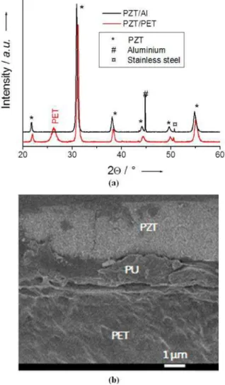
Structural characterizations are given in Figure 2: panel (a) X-ray diffraction (XRD) patterns of PZT on aluminum and transferred to PET, and panel (b) cross-section SEM image of PZT transferred on PET. XRD patterns of PZT/Al and PZT/PET are roughly the same except for the substrates peaks. All the peaks of PZT remain at their positions but the peak of aluminum disappears in the pattern of PZT/PET and is replaced by the peak of the polymer substrate. The slight difference in 2V angle observed is a consequence of the flexi-ble substrates used. They induce different base surfaces for the two cases, leading to shifts in the 2V angle.
The cross-section SEM image of transferred PZT (Fig-ure 2 b) has been realized to estimate the bond strength be-tween PZT and PU and bebe-tween the two layers of polymer. SEM observations reveal good adhesion between the oxide layer and the stack of polymers.
The transferred structure (PZT/PET) must be poled before any electric tests. In order to induce macroscopic pie-zoelectric properties to the transferred PZT, a static electric field is applied through the interdigitated electrodes. A
pho-Figure 1.Photographs of a) PZT/Al structure and b) PZT/PET IDE structure.
Figure 2.a) XRD patterns of PZT before and after transfer from the aluminum substrate to the PET substrate. b) Cross-section SEM images of PZT trans-ferred onto polymer.
tograph of the poling bench is presented in Figure 3. The sample is preheated at a temperature of 100 8C by using a hot plate. This is realized to prevent the risks of electric breakdown during the poling step. A DC field of 50 kV cm@1
is applied for 2 hours and the electric field is maintained while the temperature of the PZT/PET returns to ambient. With higher electric field values, many breakdowns occur and damage the PZT sample or the IDE.
Bending mechanical excitations around 2 Hz are applied manually on a PZT/PET beam clamped at one end. The order of magnitude of the deflection at the free end is 10 mm. The delivered voltage is recorded using an oscillo-scope with three different load resistances. The sample ex-hibits a very weak capacitance around 1.6 pF, which leads to a high optimal load resistance, close to 49 GW. In the labora-tory, the maximal load resistance available is only 100 MW, which allows extrapolation of the maximum power that a micro-generator PZT/PET could deliver. Theoretical curves were calculated for harmonic deformations of 2 Hz with a piezoelectric current of 115 nA. They are plotted in Figure 4 with the three experimental measurements realized at load resistances of 1, 10, and 100 MW. Good agreement between the experiment and the theory is observed.
In theory, the open-circuit voltage may be of 5.6 kV and the maximal power could reach 160 mW at the optimal load resistance. The energy density, Emax, of the micro-generators
is calculated using the following formula where I0is the
pie-zoelectric current, C is the capacitance, S is the active sur-face, and f is the mechanical excitation frequency:
Emax¼ I2
0
8pCSf2
A maximal energy density of 20 mJ cm@2 is obtained with
an active surface of 4 cm2(red perimeter in Figure 7). These
theoretical results are promising but need to be confirmed by measurements.
The experimental set-up is an important point in the output power measurements because of the characteristics of the external stress (magnitude, frequency if harmonic excita-tion) applied to micro-generators. Thus, it is difficult to com-pare results from the literature data directly. The closest me-chanical excitation features we have found in the literature are those used by Park et al.[7]With their high-cost process, a
micro-generator made of PZT on polymer reached a maxi-mal energy density of 259 mJ cm@2.[7] This value is 10 times
larger than the harvested energy with PZT transferred onto polymer presented in this article but the excitation is still not exactly the same. A quasi-harmonic deformation was used for the measurements presented here, while the Park team applied punctual stress in both the upward and downward di-rections. In the two cases, the voltage signals appear to be si-nusoid, but when the method employed by Park is used, higher output voltages are obtained, as it is demonstrated in the following paragraph.
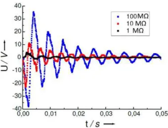
Other promising results were obtained with bending PZT/ PET samples when they are punctually deflected and subse-quently released. The three curves presented in Figure 5 cor-respond to the signal delivered by the micro-generator with the 1, 10, and 100 MW load resistances. High voltage peak amplitudes around 35 V were recorded with a load resistance of 100 MW. This is promising for future applications that will be developed to harvest energy from low frequency mechani-cal excitations.
The piezoelectric current produced with the IDE structure is smaller than the one already obtained with the same PZT Figure 3.PZT poling bench for IDE samples.
Figure 4.Voltage, current, and power delivered by PZT/PET under mechanical excitation at 2 Hz: a) experiment and theory, b) zoom on power and voltage curves.
with an MIM structure ( & 2 mA[4]). That means that the
pie-zoelectric properties of PZT samples with IDE structure are certainly lower than those with MIM electrodes structure. A solution to improve the piezoelectric properties of the PZT with IDE is to optimize the poling procedure.
Conclusions
A chemical process for transfer of PZT to a polymer sub-strate is described in this article. The realization of the PZT by CSD on a sacrificial substrate is complementary with chemical techniques used to transfer the piezoelectric layer onto the polymer. The developed process could be easy to industrialize. Structural characterizations were realized to ensure good adhesion between the different layers after the transfer and to check the crystalline quality of the PZT. It appears that the transfer is effective and that the crystalline quality is preserved after transfer. Finally, energy harvesting tests were made after implementing an IDE structure on the top surface of the PZT thin film with a polymer substrate. Only three load resistances were tested due to the very low capacitance of the generators, which implies a shift of the op-timal load towards the high resistance values. The three ex-perimental values of output current, voltage, and harvested power are in good agreement with the theoretical curves. A theoretical maximum value of 5600 V was found for the open-circuit voltage. A maximum power of 160 mW and a maximum energy density of 20 mJ cm@2 were calculated by
extrapolation with the theory. Those interesting values should be weighted by the fact that they are only obtained using theoretical calculations. An experiment with higher load resistance is already envisioned to confirm the results presented in this article.
Experimental Section
PZT thin layer fabrication began with the preparation of a pre-cursor solution, which was obtained by mixing different chemical
products. Initially, lead acetate was dissolved in a solution of acetic acid using a reflux technique. Zirconium n-propoxide and titanium n-propoxide were mixed in the desired proportions to obtain a Zr/Ti ratio of 54/46 and added to the lead solution. The final precursor solution was obtained by adding ethylene glycol, which limited the crack formations in PZT thin film during its thermal treatment.
The precursor solution was then deposited using a spin-coating technique on a sacrificial substrate, that is, an aluminum thin foil, which could be etched later using a simple chemical process. A stainless steel support was used in order to facilitate the spin-coating deposition. This technique allowed the formation of a piezoelectric film on the complete surface of the aluminum sub-strate. The rotation speed (6000 rpm) and spinning duration (20 s) were chosen according to the desired thickness of the thin layer (300 nm). After each spin-coating step, the material was subjected to a thermal treatment at temperature of 650 8C for the duration of 2 min to crystallize the PZT thin layer. In prac-tice, the thickness of the PZT thin layer obtained after the exe-cution of one time spin-coating step was about 300 nm. Thus, to form a thicker PZT thin film, deposition step could be repeated as many times as necessary to obtain a thin film of several micro-meters. Figure 6 provides schematic illustrations of the next three steps of the PZT transfer on plastic substrate.
To ensure good adhesion between the piezoelectric layer and the further substrate, a thin adhesive layer of polyurethane (PU, NOA81, Norland OpticsU) was added onto PZT by spin-coating. The adhesive layer was exposed to UV light for 2 h, to evaporate solvents and reach the final mechanical properties of the adhe-sive layer (UV curing). Polyurethane NOA81 has elastic nature, which is required for the fabrication the flexible piezoelectric structure and it ensured good bond strength between the PZT and the polymeric materials. The separation from the aluminum ground plane needed to occur before the realization of IDE. However, PZT thin films are not enough rigid to stand alone, so they must be fixed on the new polymer substrate.
A thick elastic polymer layer of 75 mm was attached on the PU adhesive using a thermofusing technique: a small pressure and heat were applied to create good adhesion between the two poly-mer layers. The permanent substrate of the final flexible
piezo-Figure 5.Voltage delivered by PZT/PET following a punctual deflection and subsequent release.
electric structure was then formed. Commercial polyethylene ter-ephthalate (PET) was a suitable thermoplastic material for the new substrate because it is an elastically deformable and low-cost polymer. Furthermore, several PET thicknesses were avail-able to tune the mechanical properties of the final multilayer in-cluding stiffness and flexibility.
At this point, the obtained structure still comprised the alumi-num sacrificial substrate. This structure was immersed in an iron chloride solution of formula FeCl3to undergo a selective
chemi-cal etching of the aluminum foil. The chemichemi-cal agent iron chlo-ride FeCl3etched aluminum in less than 5 min when a pure
solu-tion was used at room temperature. It appeared to be inactive in the presence of piezoelectric and polymeric materials (PZT, PU, and PET).
A basic flexible piezoelectric structure was finally obtained after the total dissolution of aluminum. The crystalline piezoelectric thin film was fixed on a stack of elastically deformable polymeric layers, which were used as the flexible permanent substrate. This structure was free of ground plane and completely flexible. To finalize the interdigitated structure, electrodes were evaporat-ed through a shadow mask. The dimensions of the IDE design were given in Figure 7.
The whole active surface was around 4 cm2 including all the
digits and the connexions lines. The length of one digit was 1.5 cm, its width was 200 nm, and the gap between two digits was
300 nm. Gold and aluminum electrodes of 200 nm of thickness were tested. The best results were obtained with gold because of its better flexibility. With aluminum, electrode discontinuity could happen during experiments.
XRD patterns were obtained using a Bruker D8 diffractometer with CuKaradiation (l = 1.5406 c) and scanning from 2q = 208 to
2q = 608 at a 0.038 scan rate. A Carl Zeiss Merlin SEM was used to realize cross-section images with electron energy set to 3 keV.
Acknowledgements
The authors would like to thank Jean-Emmanuel LechÞne from Cookson SAS (Cholet, France) for his receptiveness to supply the shadow masks required for electrode deposition. This work was supported by the French region Pays de la Loire through the 2014 07965 contract.
Conflict of interest
The authors declare no conflict of interest.
Keywords: chemical transfer · energy conversion · interdigitated electrodes · polymers · PZT thin films
[1] L’USINE Nouvelle, http://www.usinenouvelle.com/editorial/l-eton- nant-arbre-a-vent-de-new-wind-agite-ses-feuilles-et-electrise-la-cop21.N367355, accessed in February 2016, in French.
[2] R. Seveno, D. Averty, J. Sol-Gel Sci. Technol. 2013, 68, 175 – 179. [3] T. Dufay, B. Guiffard, J.-C. Thomas, R. Seveno, J. Appl. Phys. 2015,
117, 204101.
[4] R. Seveno, J. Carbajo, T. Dufay, B. Guiffard, J. C. Thomas, J. Phys. D 2017, 50, 165502.
[5] R. Seveno, B. Guiffard, J.-P. Regoin, Funct. Mater. Lett. 2015, 08, 1550051.
[6] R. Seveno, B. Guiffard, T. Dufay, J. C. Thomas, 2015 Jt. IEEE Int. Symp.on the Appl. Ferroelectr.(ISAF), Int. Symp. on Integr. Funct.(I-SIF), and Piezoelectric Force Microsc. Workshop (PFM), 2015, IEEE CFP15ISA-POD, ISBN 978-1-4799-9975-0, pp. 94 – 97.
[7] K.-I. Park, J. H. Son, G.-T. Hwang, C. K. Jeong, J. Ryu, M. Koo, I. Choi, S. H. Lee, M. Byun, Z. L. Wang, K. J. Lee, Adv. Mater. 2014, 26, 2514 – 2520.
[8] Y. H. Do, W. S. Jung, M. G. Kang, C. Y. Kang, S. J. Yoon, Sens. Actua-tors A 2013, 200, 51 – 55.
[9] Y. H. Do, M. G. Kang, J. S. Kim, C. Y. Kang, S. J. Yoon, Sens. Actua-tors A 2012, 184, 124 – 127.