1
Classification of flow patterns in rectangular shallow reservoirs
MATTHIEU DUFRESNE, postdoctoral researcher, University of Liège (ULg), ArGEnCo department, MS2F sector, Hydrology, applied hydrodynamics and hydraulic constructions (HACH), Chemin des chevreuils, 1, bât B52/3, étage +1, 4000 Liège, Belgium. E-mail: [email protected]
BENJAMIN J. DEWALS, postdoctoral researcher of the Belgian fund for scientific research (F.R.S.-FNRS), University of Liège (ULg), ArGEnCo department, MS2F sector, Hydrology, applied hydrodynamics and hydraulic constructions (HACH), Chemin des chevreuils, 1, bât B52/3, étage +1, 4000 Liège, Belgium. E-mail: [email protected]
SÉBASTIEN ERPICUM, laboratory manager, University of Liège (ULg), ArGEnCo department, MS2F sector, Hydrology, applied hydrodynamics and hydraulic constructions (HACH), Chemin des chevreuils, 1, bât B52/3, étage +1, 4000 Liège, Belgium. E-mail: [email protected]
PIERRE ARCHAMBEAU, research scientist, University of Liège (ULg), ArGEnCo department, MS2F sector, Hydrology, applied hydrodynamics and hydraulic constructions (HACH), Chemin des chevreuils, 1, bât B52/3, étage +1, 4000 Liège, Belgium. E-mail: [email protected]
MICHEL PIROTTON, professor, University of Liège (ULg), ArGEnCo department, MS2F sector, Hydrology, applied hydrodynamics and hydraulic constructions (HACH), Chemin des chevreuils, 1, bât B52/3, étage +1, 4000 Liège, Belgium. E-mail: [email protected]
Abstract
This work focuses on the experimental classification of flow patterns in rectangular shallow reservoirs, including symmetric flows without any reattachment point to asymmetric flows with one reattachment point, two reattachment points, or two reattachment points and one detachment point. The median position and the natural variability of the reattachment lengths
2
of asymmetric flows were measured for forty geometric and hydraulic conditions. The effects of dimensionless flow depth, Froude number, lateral expansion ratio and dimensionless length on the median reattachment lengths were analyzed. A number of regression equations were proposed. For “high” dimensionless flow depths and a Froude number of 0.20, a shape parameter was proposed for predicting the transition between symmetric and asymmetric flows. The results of this study are useful knowledge for improving current methods to predict the trapping efficiency and the preferential regions of deposition in reservoirs.
Keywords: Asymmetric flow, classification, flow pattern, reattachment, shallow reservoir, symmetry
1 Introduction
Flow detachment and reattachment processes are common in hydraulic engineering; examples are flows over lateral expansions (Abbott and Kline 1962, Chu et al. 2004), flows over groynes (Uijttewaal et al. 2001, Yeo et al. 2005), or flows in tanks (Frey et al. 1993, Stovin and Saul 1994, Oca et al. 2004), involving generally flows with sudden geometric variations. This study focuses on turbulent free-surface flows in rectangular shallow reservoirs in the context of reservoir sedimentation (Garde et al. 1990). Since the flow primarily controls sedimentation, the knowledge of its pattern is a prerequisite for determining the spatial distribution of deposits, to well-define a sediment removal strategy for a reservoir.
It is assumed that the flow is governed by nine parameters, namely L = length of reservoir, ΔB = lateral expansion, b = widths of inlet and outlet channels, h = flow depth, U = mean depth-averaged velocity, τ = bed shear stress, ρ = water density, μ = water viscosity and g = gravitational acceleration. Using dimensional analysis (Langhaar 1951), these variables involving time, mass and length unities can be reduced to six dimensionless parameters:
3
Lateral expansion ratio ΔB/b, dimensionless length L/ΔB, dimensionless flow depth h/ΔB, Froude number F = U/(gh)1/2, Reynolds number R = 4ρUh/μ, and bed friction number cfΔB/2h. Here, cf = 2τ/ρU2 = bed friction coefficient, estimated using a ‘Colebrook’ formula,
as recommended by the ASCE Task Force (e.g. Henderson 1966).
Abbott and Kline (1962) demonstrated that the recirculation zones at each side of double-lateral expansions were equal in length for an expansion ratio lower than 0.25 (symmetric flow with two reattachment points) but different in length for an expansion ratio larger than 0.25 (asymmetric flow with two reattachment points).
Kantoush (2008) noted that decreasing the dimensionless length (from 3.2 to 2.7) induced a transition from asymmetric flow to symmetric flow without any reattachment. Based on his test data and additional numerical simulations, several attempts were made to define a criterion for predicting the flow pattern in rectangular shallow reservoirs, from the simplest length to breadth ratio (Kantoush 2007) to more complex criteria involving reservoir length, its width (eventually the lateral expansion) and the inlet channel width (Kantoush 2008, Dewals et al. 2008, Dufresne 2008). However, the relatively few conditions investigated raise the question of the general validity of these criteria.
When decreasing the dimensionless flow depth (but increasing F at the same time), Kantoush (2008) indicated that the flow was not steady anymore but starts to meander. This behavior is similar to observations of Giger et al. (1991) on plane turbulent jets in shallow water and those of Chen and Jirka (1995) on turbulent wakes generated by two-dimensional (2D) bodies in shallow water.
Several studies indicate that the length of the recirculation zone over unilateral expansions depends only on the lateral expansion for small values of the bed friction number; for large values, however, the reattachment length depends only on a friction length scale (Babarutsi et al. 1989, Babarutsi and Chu 1991, Chu et al. 2004).
4
Abbott and Kline (1962) claimed that the flow pattern was not sensitive to the Reynolds number R, provided that the flow is fully turbulent upstream of the expansion. Casarsa and Giannattasio (2008) showed that the effect of R on the shorter recirculation length is not completely negligible. As the present study only focuses fully turbulent flows, transitions from symmetric to asymmetric flows encountered at small R are not further considered (e.g. Cherdron et al. 1978, Fearn et al. 1990, Maurel et al. 1996).
To the authors’ knowledge, the effect of F on the flow pattern has never been thoroughly studied. Only Kantoush (2008) carried out one test, decreasing F from 0.10 to 0.05 while keeping constant the dimensionless flow depth. His results did not highlight any significant effect of this parameter.
The aim of this study is firstly to describe the flow patterns encountered in rectangular shallow reservoirs, secondly to investigate the effects of the lateral expansion ratio, dimensionless length, dimensionless flow depth and Froude number, provided that the Reynolds and the bed friction numbers are high and low, respectively, so that they do not significantly influence the flow pattern. Thirdly, predictive criteria for the flow patterns are determined. This work therefore consists of an extension of results available in terms of lateral expansion ratio, and dimensionless length, adding original investigations on the effects of dimensionless flow depth and Froude number.
2 Experimental investigation
2.1 Experimental set-up
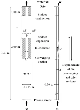
The tests were carried out at the laboratory of engineering hydraulics, University of Liège, Belgium. The experimental set-up shown in Fig. 1 consisted of a 10.40 m long and 0.985 m wide glass channel in which blocks were arranged to reproduce various geometries of rectangular reservoirs. The flume base was horizontal. The flow entered the channel from a
5
stilling basin through a porous screen to prevent fluctuations in water level and make the velocity field uniform. The flow was then contracted to the inlet channel width b along a converging section of circular shape. The reservoir inlet section with straight parallel walls was 2.00 m long. At reservoir entrance, the flow abruptly expanded to the reservoir width B = b + 2ΔB. At the reservoir exit, the flow then suddenly contracted to the outlet channel width b, whose length was 1.00 m; its downstream control involved a gate and a waterfall. All surfaces were made of glass, except for the two parallel PVC walls of the inlet and outlet channels and the converging section made of metal sheet. To vary the lateral expansion ratio, blocks of ΔB = 0.250 and 0.350 m were used, and an additional glass wall was placed along one flume wall for selected tests to reduce the reservoir width from B = 0.985 m to 0.780 m.
Figure 1 Sketch of test set-up (a) plan, (b) side view
Discharge was measured with an electromagnetic flowmeter upstream of the flume and with a triangular weir downstream of the waterfall. The reservoir flow depth was measured axially with a level meter downstream of the reservoir entrance and 0.10 m
6
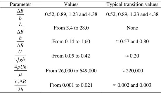
upstream of the reservoir exit. The maximum difference between the two values was 0.002 m. Therefore, only the upstream value is reported below. The range of test conditions is given in Table 1; “typical transition values” refer to these investigated as the horizontal geometry was varied to define the transition between symmetric and asymmetric flows. The water temperature was between 18 and 20°C. To check reproducibility, all tests for which the flow was stable were repeated. The tolerance in the reservoir dimensions was about ±0.0025 m. The uncertainty was about ±0.001 m in flow depth and about ±0.005 m/s in velocity, except for low flow depths of h ≈ 0.050 m and the narrow inlet channel of b = 0.080 m for which it was up to ±0.02 m/s. Detailed test conditions and results are available on request (Dufresne 2009).
Table 1 Range of test conditions
Parameter Values Typical transition values
B b ∆ 0.52, 0.89, 1.23 and 4.38 0.52, 0.89, 1.23 and 4.38 L B ∆ From 3.4 to 28.0 None h B ∆ From 0.14 to 1.60 ≈ 0.57 and 0.80 U gh From 0.05 to 0.42 ≈ 0.20 4 Uhρ µ From 26,000 to 649,000 ≈ 220,000 2 f c B h ∆ From 0.001 to 0.021 ≈ 0.002 and 0.003 2.2 Flow tests
Visual investigations employing dye injection indicated the flow patterns: Symmetry or asymmetry, number of circulation zones, and approximate locations of reattachment points. Because of the wake zone located downstream of the reservoir entrance, successive dye injections were generally needed to describe a “mean” behavior.
7
The reattachment length is defined as the distance from the beginning of the lateral expansion to the location upstream of which the longitudinal velocity is negative (from downstream to upstream) and downstream of which the longitudinal velocity is positive (from upstream to downstream). To the knowledge of the authors, only the median position has been reported in the literature, using, for example, visualization of displacement of confetti on the water surface (Babarutsi et al. 1989, Babarutsi and Chu 1991, Chu et al. 2004). Only Abbott and Kline (1962) characterized fluctuations of the reattachment lengths by carrying out a large number of tests. Herein, these fluctuations are characterized by determining the velocity distribution along the wall near the median reattachment point. This information is crucial since a strong unsteadiness is likely to cause resuspension of deposits over a large area. Once the reattachment point had been roughly located by dye visualization, the method consisted in injecting drops of dye with a syringe against the wall near the reattachment point at various streamwise locations x. At each point, 100 drops of dye were injected at a frequency of one drop per 2 s; for each drop, the flow direction was observed by eye at the syringe exit. A dye displacement from up- to downstream corresponded to a positive velocity, whereas a displacement from down- to upstream to a negative velocity. The number of injected drops and the duration of measurement (100 times 2 s) were selected after preliminary tests to ensure a statistically significant result. As the present objective was to study deposits, the reattachment lengths were measured 0.04 m above the reservoir bottom. A “reasonable” two-dimensionality of the flow was checked by dye visualization.
A 95% confidence interval of the proportion of negative velocities was calculated using a small sample method to estimate the “uncertainty” of each measurement (Wonnacott and Wonnacott 1977). The 95% confidence intervals of the median reattachment lengths were determined using interpolations of the upper-bounds and lower-bounds of the confidence intervals between locations for which the proportions are closest to 50%.
8
Additional information concerned the reattachment lengths fit by a normal distribution. By minimizing the sum of the differences between measured and normal proportions in square, its mean µi, and the standard deviation, σi of a Gaussian distribution were determined.
All the test results are available on request (Dufresne 2009).
3 Results
3.1 Flow patterns
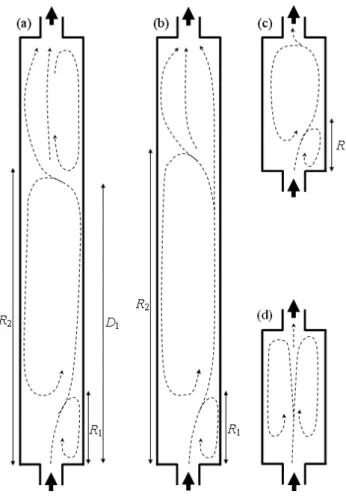
Dye visualizations highlighted five different flow patterns (Fig. 2). For short reservoirs, the flow follows a symmetric behavior S0, with a straight jet from the reservoir entrance to the exit, forming two symmetric circulation zones along either jet side (Fig. 2d).
Figure 2 Schemes of four stable flow patterns: (a) A3, (b) A2, (c) A1, (d) S0
Symmetry disappears by increasing dimensionless reservoir length, resulting in pattern A1. The jet is deflected on either reservoir side, depending on test conditions. It reattaches the
9
wall after a distance R1, leading to the formation of a large circulation zone (Fig. 2c). A
smaller circulation zone occurs upstream of the reattachment point.
For intermediate dimensionless reservoir lengths, the flow does not stabilize despite steady boundary conditions, fluctuating between the symmetric (S0) and asymmetric (A1) flow patterns. These fluctuations were not periodical and appeared to be completely random. This flow pattern is denoted by A1/S0. Even if the flow was unsteady in this situation, it differed from the meandering jet with a periodic behavior, as observed by Kantoush (2008) by decreasing the flow depth near the transition between symmetric and asymmetric flows.
Increasing again dimensionless reservoir length, the flow still remains asymmetric with pattern A2 (Fig. 2b). As for the pattern A1, the flow reattaches on one reservoir side at distance R1 but further on the opposite wall at distance R2. The flow was then fully reattached
in the reservoir downstream zone.
For long reservoirs, decreasing the dimensionless flow depth eventually led to the formation of a third recirculation zone. The flow then detaches from the wall of the first reattachment at distance D1 from the reservoir entrance. This third asymmetric pattern is
denoted by A3 (Fig. 2a).
3.2 Unsteadiness of reattachment
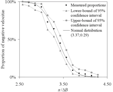
Figure 3 shows the negative velocity distribution near the first reattachment for Test F4-a (ΔB/b = 1.23, L/ΔB = 20.0, h/ΔB = 0.57, F = 0.20; R = 210,000, cfΔB/2h = 0.003), involving
flow pattern A2. The abscissa is the ratio of distance from the upstream face to the lateral expansion. Using Fig. 3, the median reattachment length and the fluctuations range of the reattachment length may be determined. For example, the median value of the dimensionless reattachment length R1 is between 3.31 and 3.46 at a confidence level of 95%. Using the
10
between about 3.01 and 3.74 during 80% of the time; it was smaller than 3.01 during 10%, and larger than 3.74 during 10% of the time. Still velocities in Fig. 3 is cut at the end
Figure 3 Proportion of negative velocities near first reattachment point of Test F4-a A comparison with the results obtained for the second reattachment length for the same Test F4-c highlights the different nature of the two reattachment lengths. Whereas the first was almost steady with σ1/ΔB = 0.29, the second was highly unsteady with σ2/ΔB = 6.0
(Dufresne 2009). Therefore, the second reattachment length fluctuated over a longer distance on the reservoir wall. For example, the dimensionless reattachment length was smaller than 10.6 during 10% of the time whereas the median value was 18.3. An increase of the median reattachment length also induces an increase of the natural variability. For Test F19-a (ΔB/b = 0.52, L/ΔB = 28.0, h/ΔB = 0.80, F = 0.20, R = 224,000, cfΔB/2h = 0.002), σ2/ΔB =
2.0 if μ2/ΔB = 10.0, as compared to 6.0 and 18.3 for Test F4-c, respectively.
The effects of dimensionless flow depth, Froude number, lateral expansion ratio and dimensionless length on the median reattachment lengths were investigated for the asymmetric flow patterns. This investigation mainly focused on the first reattachment length and only few tests were conducted on the second, because of the generally large “characteristic time”. For the same reason, detachment lengths were not measured precisely.
11 3.3 Influence of dimensionless flow depth
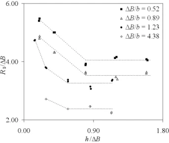
The effect of dimensionless flow depth on the first reattachment length was investigated for “long” reservoirs (ΔB/b = 20.0 and 28.0) at F ≈ 0.20 (Fig. 4). As the dimensionless flow depth is increased, the first median reattachment length decreases until reaching a minimum level (dotted lines). The threshold of dimensionless flow depth above which the median reattachment is constant is around 0.8. Moreover, it was noticed that all reattachment lengths were almost constant if the dimensional flow depth was larger than ≈ 0.200 m; therefore, only this value was used below.
Figure 4 Effect of dimensionless flow depth on first median reattachment length
3.4 Effect of Froude number
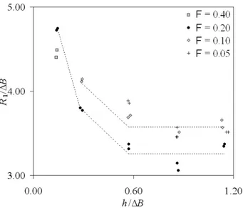
The Froude number was investigated in the range 0.05 ≤ F ≤ 0.40 for a lateral expansion ratio of 1.23 and a dimensionless length of 20.0. The tests were limited by the measurement validity of the reattachment lengths using dye visualization, because this method cannot be used if the flow is too fast, and by the discharge inaccuracy below 1.5 l/s. From Fig. 5, the dimensionless median reattachment length increases by decreasing F (despite intuitively the opposite is expected). Comparison between F of 0.20 and 0.10 indicates that the curve of
12
dimensionless median reattachment length versus dimensionless flow depth is translated downward as F increases, with the mean difference of 0.34. Whereas a similar reduction is observed for the single test condition at F = 0.40, the results obtained at F = 0.05 are close to these obtained at F = 0.10, except near the dimensionless flow depth of 0.60. Therefore, no conclusion can be drawn for F ≤ 0.10.
Figure 5 Effect of Froude number F on first median reattachment length 3.5 Effect of lateral expansion ratio
The results obtained for “long” reservoirs with ΔB/b = 20.0 and 28.0, “high” flow depths > 0.200 m and F ≈ 0.20 are now considered. The natural logarithm of R1 is plotted as a
function of the natural logarithm of the lateral expansion ratio in Fig. 6 (black points), suggesting a linear relationship. The first median reattachment length can be expressed for lateral expansion ratio in the range 0.52 to 4.38 and F ≈ 0.20 as
25 . 0 75 . 0 1 3.43 B b R ≈ ∆ (1)
Assuming the same power law and the same values of powers by modifying the Froude number, the value 3.43 should be replaced by 3.79 if F ≈ 0.10. Using limited test data on the second reattachment length and assuming the same type of power law, the second median reattachment length R2 can be expressed for F ≈ 0.20 as
13 7 . 0 7 . 1 2 15.9 − ∆ ≈ B b R (2)
From Eqs. (1) and (2), the width of the inlet channel has an opposite effect on the two reattachment lengths: Increasing b, the first increases whereas the second decreases. The same tendency was found by Abbott and Kline (1962). A re-analysis of their data leads to the following regressions for the “two-dimensional zone of separation” if the lateral expansion ratio ranges 0.25 and 2.00. The length of the shorter 2D zone of separation m1 was found to be
≈ 3.5ΔB0.8
b0.2; the lengths of the lower (subscript min) and upper (subscript max) bounds of Abbott and Kline (1962) for the longer 2D separation zone are m2,min≈ 9.2ΔB1.1b-0.1 and
m2,max≈ 10.9ΔB1.2b-0.2, respectively.
Figure 6 Effect of expansion ratio on first median reattachment length for “long” reservoirs and for “last” asymmetric flows
3.6 Effect of dimensionless length
For each lateral expansion ratio, tests were conducted to investigate the effect of dimensionless length on the median reattachment length near the transition from asymmetric to symmetric flow patterns. All these tests were made for a velocity of ≈ 0.28 m/s and a flow depth of ≈ 0.200 m, with F ≈ 0.20, and dimensionless flow depths from ≈ 0.57 to 0.80. The
14
effect of dimensionless length is shown in Fig. 6 by comparing dimensionless reattachment lengths obtained for “long” reservoirs and for the smallest lengths for which the flow pattern was asymmetric (referred to as “last”). For large lateral expansion ratios (1.23 and 4.38), the dimensionless median reattachment length slightly decreases by decreasing dimensionless length, as if the flow were longitudinally confined by the downstream reservoir walls. For an expansion ratio of 0.89, the dimensionless reattachment length was almost constant by decreasing dimensionless length. For 0.52, even if the 95% confidence intervals are partially overlapped (Dufresne 2009), the dimensionless median reattachment length is seen to slightly increase by decreasing dimensionless length. From Fig. 6 it can be concluded that the “last” median reattachment length can be approximated as
40 . 0 60 . 0 1 3.27 B b R ≈ ∆ (3)
Using Eq. (3) leads to a value of 2.74 m for the median reattachment length of the last asymmetric flow pattern (L = 6.000 m, ΔB = 1.875 m, b = 0.250 m) as observed by Kantoush (2008). This is consistent with the mean value that he extracted from his velocity data (≈ 2.65 m, Figure 4.16 of his thesis).
3.7 Forecasting criteria
Figure 7 illustrates all the experimental flow patterns observed as the geometry for “high” flow depths and F ≈ 0.20 was varied. The x- and y-axes of this figure are respectively the natural logarithms of the dimensionless length and the natural logarithm of the lateral expansion ratio. Do not state this here and even introduce new variables, these are just the ln functionsBased on the test results, the shape parameter (L/ΔB0.60b0.40) was defined as a combination of dimensionless length and lateral expansion ratios. The values of 6.2 and 6.8 are relevant to describe the transition between symmetric and unstable flow patterns, and the transition between unstable and asymmetric flow patterns, respectively. These two threshold
15
values are consistent with the results of Kantoush (2008), even if they were obtained for smaller dimensionless flow depths in the range of 0.11 to 0.60, and F = 0.10.
Figure 7 Classification diagram for flow patterns as a function of rectangular shallow reservoir geometry
The exponents of the shape parameter are identical to those of Eq. (3). A comparison between these two formulations highlights that the transition between asymmetric and symmetric flow patterns roughly occurs as the median reattachment length is half of the reservoir length.
4 Conclusions
The objective of this work was to classify the flow patterns in rectangular shallow reservoirs. Four dimensionless parameters were considered: Lateral expansion ratio, dimensionless length, dimensionless flow depth and Froude number. The flexibility of the experimental set-up enabled to easily change the reservoir length, its width and that of the inlet channel.
Four stable flow patterns were identified, from symmetric pattern without any reattachment point to asymmetric patterns with one reattachment point, two reattachment points, or two reattachment points and one detachment point. Near the transition between
16
symmetric and asymmetric patterns, an unstable flow pattern was also identified. The median position and the variability of the reattachment lengths of asymmetric flows were measured for forty geometric and hydraulic conditions, a useful database for further numerical modeling. The effects of dimensionless flow depth, Froude number, lateral expansion ratio and dimensionless length on the median reattachment lengths were analyzed, and a number of regressions were proposed. For “high” dimensionless flow depths and a Froude number of 0.20, a shape parameter was proposed to predict the transition between symmetric and asymmetric flows.
Since the flow is the primary control on sedimentation, the present classification of flow patterns is useful knowledge to predict preferential regions of deposition. Further investigations are currently in progress to investigate the effect of flow pattern on the trapping efficiency. The authors question whether the relative inaccuracy of the current empirical methods is because the reservoir trapping efficiency does not account for the flow pattern. The present work will be useful for improving this aspect.
Acknowledgments
The authors acknowledge Alain Dewart, Didier Lallemand, Maurice Salme and Dieudonné Stouvenakers for help to building the experimental set-up. The authors also acknowledge University of Liège for allocating a postdoctoral fellowship to the first author. Finally, the second author acknowledges the Laboratory of Hydraulic Constructions, EPFL, Lausanne for fruitful discussions on the topic during his postdoctoral stay in 2006-2007.
Notation
b = Width of inlet channel (m) B = Width of reservoir (m)
17 cf = Bed friction coefficient (-)
D1 = Median detachment length (m)
F = Froude number (-)
g = Gravitational acceleration (m/s2) h = Flow depth (m)
L = Length of reservoir (m)
m1 = Length of shorter 2D separation zone (m)
m2 = Band of length of longer two-dimensional separation zone (m)
R = Reynolds number (-)
R1 (R2) = First (second) median reattachment length (m)
U = Velocity in inlet channel (m/s)
x = Distance between measurement and upstream reservoir face (m) ΔB = Lateral expansion width (m)
μ = Water viscosity (kg/m/s)
μi = Mean of normal distribution around reattachment point (m)
ρ = Water density (kg/m3
)
σi = Standard deviation around reattachment point (m)
τ = Bed shear stress (kg/m/s2
)
References
Abbott, D.E., Kline, S.J. (1962). Experimental investigation of subsonic turbulent flow over single and double backward facing steps. J. Basic Engng. 84, 317-325.
Babarutsi, S., Chu, V.H. (1991). Dye-concentration distribution in shallow recirculating flows. J. Hydraulic Engng. 117(5), 643-659.
18
Babarutsi, S., Ganoulis, J., Chu, V.H. (1989). Experimental investigation of shallow recirculating flows. J. Hydraulic Engng. 115(7), 906-924.
Casarsa, L., Giannattasio, P. (2008). Three-dimensional features of the turbulent flow through a planar sudden expansion. Physics of Fluids 20(1), 5103:1-15.
Chen, D., Jirka, G.H. (1995). Experimental study of plane turbulent wakes in a shallow water layer. Fluid Dynamics Res. 16(1), 11-41.
Cherdron, W., Durst, F., Whitelaw, J.H. (1978). Asymmetric flows and instabilities in symmetric ducts with sudden expansions. J. Fluid Mech. 84(1), 13-31.
Chu, V.H., Liu, F., Altai, W. (2004). Friction and confinement effects on a shallow recirculating flow. J. Environmental Engng. Sci. 3(5), 463-475.
Dewals, B.J., Kantoush, S.A., Erpicum, S., Pirotton, M., Schleiss, A.J. (2008). Experimental and numerical analysis of flow instabilities in rectangular shallow basins. Env. Fluid Mech. 8(1), 31-54.
Dufresne, M. (2008). La modélisation 3D du transport solide dans les bassins en assainissement: Du pilote expérimental à l’ouvrage réel [Three-dimensional modelling of sediment transport in sewer detention tanks: Physical model and real-life application]. PhD thesis. Université Louis Pasteur, Strasbourg, France [in French]. Dufresne, M. (2009). Ecoulement et dépôt de sédiments dans les bassins rectangulaires peu
profonds [Flow and sediment deposition in rectangular shallow reservoirs]. Postdoctoral thesis. Université de Liège, Belgium [in French].
Fearn, R.M., Mullin, T., Cliffe, K.A. (1990). Nonlinear flow phenomena in a symmetric sudden expansion. J. Fluid Mech. 211, 595-608.
Frey, P., Champagne, J.Y., Morel, R., Gay, B. (1993). Hydrodynamics fields and solid particles transport in a settling tank. J. Hydraulic Res. 31(6), 736-776.
19
Garde, R.J., Ranga Raju, K.G., Sujudi, A.W.R. (1990). Design of settling basins. J. Hydraulic Res. 28(1), 81-91.
Giger, M., Dracos, T., Jirka, G.H. (1991). Entrainment and mixing in plane turbulent jets in shallow water. J. Hydraulic Res. 29(5), 615-642.
Henderson, F.M. (1966). Open channel flow. Macmillan, New York.
Kantoush, S.A. (2008). Experimental study on the influence of the geometry of shallow reservoirs on flow patterns and sedimentation by suspended sediments. PhD thesis 4048. EPFL, Lausanne, Switzerland.
Kantoush, S.A. (2007). Symmetric or asymmetric flow patterns in shallow rectangular basins with sediment transport. Proc. 32nd IAHR Congress, Venice, Italy (CD-Rom).
Langhaar, H.L. (1951). Dimensional analysis and theory of models. Wiley, New York.
Maurel, A., Ern, P., Zielinska, B.J.A., Wesfried, J.E. (1996). Experimental study of self-sustained oscillations in a confined jet. Physical Review E 54(4), 3643-3651.
Oca, J., Masaló, I., Reig, L. (2004). Comparative analysis of flow patterns in aquaculture rectangular tanks with different water inlet characteristics. Aquacultural Engng. 31 (3-4), 221-236.
Stovin, V.R, Saul, A.J. (1994). Sedimentation in storage tank structures. Water Sci. and Tech. 29(1-2), 363-372.
Uijttewaal, W.S.J., Lehmann, D., van Mazijk, A. (2001). Exchange processes between a river and its groyne fields: Model experiments. J. Hydraulic Engng. 127(11), 928-936. Wonnacott, T., Wonnacott, R. (1977). Introductory statistics, 3rd ed. Wiley, New York.
Yeo, H.K., Kang, J.G., Kim, A.J. (2005). An experimental study on tip velocity and downstream recirculation zone of single groynes of permeability change. KSCE J. Civil Engng. 9(1), 29-38.