HAL Id: hal-01008225
https://hal.archives-ouvertes.fr/hal-01008225
Submitted on 10 May 2018HAL is a multi-disciplinary open access archive for the deposit and dissemination of sci-entific research documents, whether they are pub-lished or not. The documents may come from teaching and research institutions in France or abroad, or from public or private research centers.
L’archive ouverte pluridisciplinaire HAL, est destinée au dépôt et à la diffusion de documents scientifiques de niveau recherche, publiés ou non, émanant des établissements d’enseignement et de recherche français ou étrangers, des laboratoires publics ou privés.
Finite element damage prediction of composite
structures
Laurent Gornet
To cite this version:
Laurent Gornet. Finite element damage prediction of composite structures. The 12th International Conference on Composite Materials: ICCM12, 1999, Paris, France. �hal-01008225�
FINITE ELEMENT DAMAGE PREDICTION OF
COMPOSITE STRUCTURES
L. Gornet
Laboratoire Mécanique et Matériaux, Division Mécanique des Structures, Ecole Centrale Nantes, 1 rue de la noë,BP 91101, 44321 Nantes cedex 03, France
SUMMARY: This study recalls the basic principles of a general damage computational
approach for laminates and shows its possibilities for simulating the complete fracture phenomenon in the case of complex structures. For composites, continuum damage mechanics models are recalled. They are constitutive relations which, when included in a structural analysis code, are able to predict the damage state at any time and at any point of the studied structure until final fracture. The predictions are obtained with an extended version of the Finite Element code Castem 2000 (C.E.A.) developed specifically for laminate composite structures. This study describes, for carbon-fiber/epoxy-resin laminated composites, some examples of damage and delamination predictions by means of a damage mechanics computational approach.
KEYWORDS: Damage Mechanics, Finite Element Predictions, Delamination .
INTRODUCTION
The aim of this paper is to present examples of damages and delamination predictions by means of a damage mechanics computational approach. Three-dimensional non-linear Finite Element (FE) analyses are conducted for standard delamination tests. Damage refers to the more or less gradual development of microvoids and microcracks which lead to macrocracks and then to fracture. Brittle and progressive damage mechanisms are both present. To simulate the complete fracture phenomenon, a mesomodelling of the material is recalled. This is a semi-discrete damage mechanics approach where the material is described on an intermediate and preferential scale known as the meso-scale. The use of classical damage modelling for the simulation of failure has led to many theoretical and numerical difficulties which are well understood at the present time. With the concept of meso-model, where the state of damage is uniform in each meso-consistuent, main of these difficulties are overcome. This type of modelling, which has a strong physical significance, is not a continuous mechanical one but a semi-discrete one and particular lengths are introduced: the thickness of a single layer for example. In order to obtain a complete consistent computational damage approach, damage model with delay effects has been used. For this model, a variation of the stresses does not lead to an instantaneous variation of the damage variable which is physically correct. There is a certain delay defined by the characteristic time included in the model. In quasi-static problems, the use of such damage evolution laws implicitly introduces a length scale into the governing equations of the problem and then avoids the pathological mesh sensitivity for composite structures. Even though the purpose of this work is quite general, this application concerns the M55J/M18 carbon-fiber/epoxy-resin material which a high
modulus carbon-fiber/epoxy-resin material. Examples of comparisons between prediction and experimental results are provided.
GENERAL TOOLS AND CONCEPTS
Damage concept
The main idea is originally due to Kachanov [1] and Rabotnov [2]: the deterioration of a material can be described by its effects on the elastic coefficients. The classical theory of isotropic damage developed in particular by Lemaitre [3] for metallic is not sufficient to study composite materials. A general approach which is useful in describing damage mechanisms, associated forces and constitutive laws, has been proposed by Ladeveze [4] [5] [6]. Applications to different material composites are given in [7] [8]. Other approachs for composites are proposed by Talreja [9], Allen et al [10]. At the present time, continuum damage mechanics approaches are numerous. The predictions are obtained with an extended version of the Finite Element code Castem 2000 (C.E.A.) [11] developed specifically for laminate composite structures. This code include the damage mesomodel based on two constituents: the elementary layer and the interface. The code is able to compute at any time and at any point, the "intensity" of the different damage mechanisms occurring in the different layers and interfaces. Examples of delamination predictions are shown in [12].
Meso-modeling-concept
For laminates, three different scales can easily be defined: the micro-scale of the individual fiber, the meso-scale associated with the thickness of the elementary ply, and the macro-scale which is the structural one. Due to the low thickness of the elementary ply and the kinematics of the deterioration inside the ply (fiber-oriented), it is possible and worthwhile to derive a material model at the scale. The one proposed in [6] is defined by two meso-constituents: a single layer, and an interface which is a mechanical surface connecting two adjacent layers and dependent on the relative orientation of their fibers (see Fig. 1).
ply
-ply +
interface
1
2
3
Fig. 1: Laminate modeling and Orthotropic directions of the interface
A meso-model is then defined by adding another property: a uniform damage state is prescribed throughout the thickness of the elementary ply. This point plays a major role when trying to simulate a crack with a damage model. With this property, Damage Mechanics integrate Fracture Mechanics, i. e. it yields a correct value of the critical energy release rate. Let us recall that in order to be able to perform complete analyses of three-dimensional delamination process cases, damage models with delay effects are introduced for the in-plane direction of both the layer and interface. One limitation of the proposed meso-model is that the fracture of the material is described by means of only two types of macrocracks,
delamination cracks within the interfaces and orthogonal cracks to the laminate with each cracked layer being completely cracked in its thickness. Let us recall that the single-layer model and its identification, including damage such as fiber-breaking and transverse micro-cracking, as well as inelastic effects were previously developed in [6][8].
Interface modeling
The interface model is detailed next. The interlaminar connection is being modeled as a two-dimensional entity that ensures stress and displacement transfers from one ply to another(see Fig. 1). This model was previously developed in [13], and F.E. examples of delamination predictions are shown in [12]. The notions and framework that govern the interface damage model are similar to those which are used to derive the layer damage model [6][8]. The effect of the deterioration of the interlaminar connection on its mechanical behavior is taken into account by means of internal damage variables. The different types of damageable behavior in "tension" and in "compression" are distinguished by splitting the strain energy into "tension-energy" and "compression-energy". More precisely, we use the following expression, proposed in [6] for the energy per unit area :
ED = 1 2
[
<-σ33>2 + k30 + <σ33>2 + k30 (1-d3) + σ2 32 k20 (1-d2) + σ312 k10 (1-d1)]
(1) Thus three internal damage indicators, associated with the three Fracture Mechanics modes, are introduced (see Fig. 2).! " " " ! ! # # # !"#$%& !"#$%' !"#$%(
Fig. 2: Fracture Mechanics modes
where k i0 is an interlaminar stiffness value and di the internal damage indicator associated with its Fracture Mechanics mode, while subscript i corresponds to an orthotropic direction of the interface (see Fig. 2). Classically, the damage energy release rates, associated with the dissipated energy φ by damage and by unit area, are introduced as:
Yd3 = 1 2 <σ33>2 + k30 (1-d3)2 ; Y d1 = 1 2 σ2 31 k10 (1-d1)2 ;Yd2 = 1 2 σ2 32 k20 (1-d2)2 (2)
and φ = Yd3d. 3 + Yd1d. 1 + Yd2d.
2 (3)
with (3) to satisfy the Clausius-Duheim inequality. In what follows, an "isotropic" damage evolution law is described. In this model, as proposed in [14], the damage evolution law is assumed to be governed by means of an equivalent damage energy release rate of the following form:
Y (t) = sup
τ ≤ t[
(
(Yd3) α + (γ 1Yd1)α + (γ2Yd2)α)
∧τ 1/α]
(4)The evolution of the damage indicators is thus assumed to be strongly coupled. γ1, γ2 and α are material parameters. A damage evolution law is then defined by the choice of a material function ω, such that:
d3 = d1 =d2 = ω(Y) if d3 < 1 ; and d 3 = d1 =d2 = 1 otherwise (5) One simple case, used for application purposes, is:
ω(Y) = [ n n+1 <Y-Yo>+ Yc-Yo ] n (6)
where a critical value Yc and a threshold value Yo are introduced. High values of the n case
correspond to a brittle interface. To summarize, the damage evolution law is defined by means of the six intrinsic material parameters Yc,Yo, γ1, γ2, α and n. It will be shown in the next
paragraph that Yc, γ1, γ2 and α are all related to the critical energy release rates. The high values of the "n" case correspond to a brittle interface.
Links with Fracture Mechanics
A simple way of comparing Damage Mechanics with Linear Elastic Fracture Mechanics is to compare the mechanical dissipation yielded by the two approaches. This was performed in [13] and only the results are presented below. In the case of pure-mode situations, when the critical energy release rate reaches its stabilised value at the propagation denoted by (7), we obtain:
GcpI = Yc ; GcpII = Yc γ1 ; Gc p III = Yc γ2 (7)
For a mixed-mode loading situation, we simply derive a standard LEFM model:
GI GcIp α + GII GcIIp α + GIII GcIIIp α =1 (8)
wherein α governs the shape of the failure locus in the mixed mode. The identification of this interface model for the M55J/M118 material is given in [15].
Damage model with delay effects
It is well known that classical damage models lead inevitably to strain softening responses. From a fundamental point of view, this effect poses some severe mathematical difficulties that are now well understood. From a computational perspective, the numerical solution with classical local damage models exhibits a severe mesh dependence in the presence of strain softening, which leads to completely useless results. One way to avoid such difficulties is to use localization-limiter models. A large class of limiter models has been proposed. In order
to obtain, in all cases, a consistent model for the description of rupture, a variant of the previous damage model, that introduces delay effects is applied [16][17] [18]. In quasi-static problems, the use of such damage evolution laws implicitly introduces a length scale into the governing equations of the problem and then avoids the pathological mesh sensitivity for composite structures. This variant damage model ensures both that the physical variation of the driving force Y does not lead to an instantaneous variation of damage variable d3 and that the damage rate is bounded. More precisely, the rate of the damage indicator is defined by:
Y (t) =
[
(
(Yd3)α + (γ1Yd1)α + (γ2Yd2)α)
1/∧τα]
(9) d.
3 = k < ω (Y) - d3 >+n if d3<1; d3=1 otherwisewith ω (Y) < 1 ; w(Y) =1 otherwise d
.
1 = d.
2 = d.
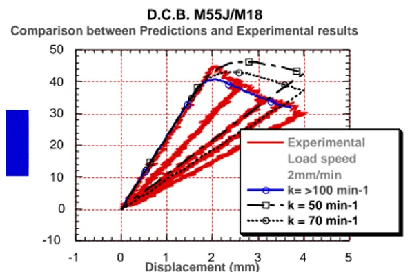
3 if d1<1; d1=1In many practical situations, a model without delay effect is sufficient. This is the case, in particular, for problems where the crack is described by a line. For example, in the case of a Double-Cantilever Beam (DCB) test, results are mesh-independent. But in the general case (three-dimensional delamination shape), the delay effect model must be used to unforced for example the mesh independence. In the case of the DCB fracture mechanics test, it is possible to identify the parameter k (inverse of a characteristic time Fig. 3) which governs the strain-softening response. -10 0 10 20 30 40 50 -1 0 1 2 3 4 5 D.C.B. M55J/M18 Experimental Load speed 2mm/min k= >100 min-1 k = 50 min-1 k = 70 min-1 Displacement (mm)
Comparison between Predictions and Experimental results
Fig. 3: Identification of the damage delay effect's characteristic time parameter (k=100min-1).
F.E. implementation of the delay effect model
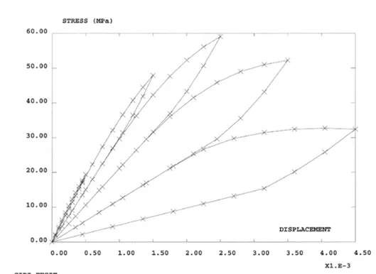
In this work, solid mechanics problems are solved by means of the finite element displacement method. The predictions are obtained with an extended version of the Finite Element code Castem 2000 (C.E.A.) [11] developed specifically for laminate composite structures. The principe of this method consists of solving, in an incremental way, the discretized equilibrium equations and the material governing equations. A special interface element of zero thickness has been used [19]. Here, we focus our attention on the implementation used to solve the delay effect damage model in the finite element code. An implicit Euler algorithm is employed, and the non-linear discretized damage equation is solved by the Newton Method. The numerical integration of the constitutive model is summarized in Table 1. A mode I prediction is shown in Fig. 4.
Table 1:
Delay Effect Damage Model Implementation: an implicit Euler algorithm is employed.
1. Compute ω(Yn+1)
2. Initialize
i =0, d3ni+1= d3n
3. Check the residual :
Rni+1=d3ni+1−d3n − ∆t k3< ω(Yn+1)−d3ni+1>n+
4. Check for convergence :
If Rni+1 <Tol, Then d3 n+1=d3ni++11 Goto5. Else :∆d3n+1 = −Rni+1 ∂Rn+1 i ∂d3 n+1 −1 ; d3 ni++11=d 3n+1 i + ∆d 3n+1 i=i+1, Goto 3. 5. Compute damages d1, d2: d1n+1 =d1n+(d3n+1−d3 n) d2n+1 =d2n +(d3 n+1−d3n) 6. Compute stress :
σ33 n+1=k30(1−d3n+1)[U3]n+1, σ23n+1 =k20(1−d2 n+1)[U2]n+1 σ13n+1=k10(1− d1n+1)[U1]n+1
7. Update and exit.
.
Fig. 4: Mode I prediction for damage delay effect's characteristic time parameter (k=40 min-1).
FINITE ELEMENT DAMAGE PREDICTION OF SPECIMEN TESTS
Several tests of delamination propagation: Double-Cantilevered Beam (DCB), Edge-Notched Flexure (ENF) and Mixed-Mode Flexure (MMF) or of initiation: edge delamination, are considered. In this study, crack growth and strain energy release rates are predicted and compared with experimental results obtained by the Aerospatiale Company for DCB, ENF and MMF tests Here we pay special attention to the basic aspects of finite element simulations of the inter laminar and intralaminar damages. Finite element prediction of classical Fracture Mechanics coupon tests are analyzed. A computation of the initiation and propagation of delamination, and more generally of laminated specimen test is presented and compared to the experiments. Tridimensional F.E. predictions of fracture mechanics specimen tests are conducted, the shape of the delaminaton front is also predicted. The tests of crack propagation in interlaminar fracture specimens are usually conducted on beam specimens with an initiated crack at the studied interface. Our specimens are 300 mm long and 20 mm wide. An anti-adhesive film 40 mm long and 25 mm in thickness is inserted at the mid-plane in order to initiate cracking. From an computational point of view, an interface of zero stiffness rigididy is used combined with unilateral contact conditions to model the initial crack (anti-adhesive film) in the F.E. predictions. The evolution of the damaged area is then refined for all test predictions. Experimental results and Finite Element predicted values exhibit good correlation (Fig. 5-6). In particular the lengths of the debonding area are found to be closed.
-10 0 10 20 30 40 50 -1 0 1 2 3 4 5 #)*)+)%!,,-.!'/%01213 456789:67%;<=>6? $@A658B6C:<=%56?>=:? $%&'()*+ ,-./0&123245()33+ 51 mm 58 mm 65 mm 67 mm 74 mm
Fig. 5: F.E. Mesh of a D.C.B. specimen test. Evolution of the delamination area at the end of the test is 23mm. Prediction of a D.C.B. test . Comparison between experimental results and predicted
-50 0 50 100 150 200 250 300 -0,5 0 0,5 1 1,5 2 2,5 Predicted values Experimental results Load (N) Displacement (mm) E.N.F. M55J/M18 [0,0] 68 mm 77 mm -50 0 50 100 150 200 -0,5 0 0,5 1 1,5 2 2,5 3 Predicted values Experimental results Load (N) Displacement (mm) M.M.F. M55J/M18 a=45.38/L=90
a=53.96 a=59.90 a=6.58 a=70.96
a=78.15
Fig. 6: Prediction of an E.N.F. test. Comparison between experimental results and predicted values. The initial crack closure is a=68mm. The evolution of the delaminattion area at the end of the test is 77mm. Prediction of an M.M.F. test. Comparison between experimental results and predicted values. The initial crack closure is a=45mm. The evolution of the delaminattion area at the end of the test is 32.77mm.
A computation of the initiation and propagation of delamination, and more generally of damages, in an M55J/M18 laminated plate is also presented and compared to the experimental data. Numerical simulations of delamination onset near the free edge of carbon-epoxy composite specimens under tension or compression have been previously studied. In this previous study, all of the damage phenomena were modeled as being concentrated on the interface. In this present work, the edge effects are computed by taking into account the damage modeling of both the interface and the layer. As another example of the possibilities of our F.E. code, let us consider the laminate structure defined in Fig. 7 where a tension loading is applied. These initial results have been obtained with the M55J/M18 material's parameters. During the loading history of the structure, a crack in the central interface (see Fig. 8)of the specimen test first appears; at the same time, cracks grow until rupture in the (+-45) layers. The usual mesh sensitivity difficulties are not present. Results are given in Fig. 7 and 8. 6 (789 : ; 6 <:3325=:(/0&42 ,>$?@A*?BAC*((DEC*B F F F ((89 (89((( (789 GF((( 0 100 200 300 400 500 600 700 800 -0,4 -0,2 0 0,2 0,4 0,6 COMPARISON SPECIMEN TEST M55J/M18 [(0)3/±(45)2/90]s F.E. CODE PREDICTION
Test up 1 : longi Test up 1 : trans Test down 2 : trans Test down 2 : longi F.E. Code
Stress (MPA)
Strain (%) Strain gages Trans Longi
Fig. 7: the laminate is a [03, (+-45)2, 90]sym M55J/M18 stacking sequence distribution layers. Response of the laminate and the F.E. prediction
Fig.8: The laminate is a [03, (+-45)2, 90]sym M55J/M18 stacking sequence distribution layers. Comparison between the prediction of the crack in the central interface of the specimen and X-ray delamination photography
CONCLUSIONS
A meso-damage mechanics modeling of laminates, whose aim is to predict the behavior of any composite structure with respect to delamination through knowing only a few characteristics of the interface, has been detailed. Predictions was conducted on M55J/M18 material specimens. Finite element examples show that this approach is promising in the prediction of delamination under various circumstances. Numerical tools, which allow the computation up to failure of the behaviour of any stacking sequence, was presented. This work represents the first step towards a global prediction of composite structures up to the complete fracture.
REFERENCES
1. Katchanov, L.M., "Time of the rupture process under creep conditions", Izv Akad Nauk
S.S.R. otd Tech Nauk, 8, 1958, pp. 26-31.
2. Rabotnov, YN, "Creep rupture", Proc. XII, Int. Cong. Appl. Mech., Stanford-Springer, 1968.
3. Lemaitre, J., "How to use Damage Mechanics", Nuclear Engineering and Design, 80, 1984, pp. 233-245.
4. Dumont, J.P., Ladevèze, P. , Poss, M. and Remond, Y., "Damage mechanics for 3D composites", Composite Structure, Vol 8, 1987 pp. 119-1414.
5. Ladevèze, P, "Sur un modéle d'endomagement anisotrope", Rap int n°34 (1983), LMT Cachan.
6. Ladevèze, P , "Sur la Mécanique de l'Endommagement des composites", CR des JNC 5, C. Bathias & D. Menkès eds, Pluralis Publication, Paris, 1986, pp. 667-683.
7. Ladevèze, P, "A Damage Approach for Composite Structures : Theory and Identification", Mechanical Identification of Composites, Vautrin, A., and Sol, H., eds., Elsevier, 1991, pp. 44-57.
8. Ladevèze, P. and Le Dantec, E. , "Damage modelling of the elementary ply for laminated composites", Comp. Sci. & Technol., Vol 43, 1992, pp. 257-267.
9. Talreja, R., "Transverse cracking and stiffness reduction in composite laminates", J. of
Comp. Mat., Vol. 19, 1985, pp. 355-375.
10. Allen, D.H., Harris, C.E. and Groves, S.E., "A Thermomechanical constitutive theory for elastic composites with distributed damage", Int. J. of Solids and Structures, Vol. 23, No. 9, 1987, pp. 1301 - 1338.
11. Verpeaux P., Charras T. et Millard A. Castem 2000., "Une approche moderne du calcul de structures", JM Fouet, P Ladeveze R Ohayon, Vol. 2, 1988, pp. 261-227.
12. Gornet L., Hochard C., Ladevèze P., Perret, L, "Examples of Delamination Predictions by a Damage Computational Approach", Proceedings DFI-1, Damage and
Failure of Interfaces, Vienna, Austria, A.A.Balkema, Rotterdam, 1997, pp. 161-169.
13. Allix, O. and P. Ladevèze, "Interlaminar interface modelling for the prediction of laminates delamination", Composite Sructures, Vol. 22, pp. 235-242., 1992.
14. Allix, O., Corigliano, A. and P. Ladevèze, "Damage analysis of interlaminar Fracture specimens", Composite Sructures, Vol. 31, 1995, pp. 61-74.
15. Allix, O., Lévêque, D. and Perret, L., "Identification and forcast of interlamination in composite laminates by an interlaminar interface model", Composite Sructures, Vol. 31, 1995, pp. 61-74.
16. Gornet, L,. "Simulation des endommagements et de la rupture dans les composites stratifiés", Thesis, Université Pierre et Marie Curie Paris 6/LMT/ENS-Cachan, ISBN 2-11-088-9705, 1996.
17. Ladevèze, P., "A damage computational method for composite structures", J.
Computer and Structure, Vol .44 (1/2), 1992, pp. 79-87.
18. Ladevèze, P. 1995. "A damage computational approach for composites: Basic aspects and micromechanical relations", Computational Mechanics, Vol. 17, 1995, pp. 142-150.
19. Beer, G., "An isoparametric joint/interface element for finite element analysis", Int.J.


![Fig. 7: the laminate is a [0 3 , (+-45) 2 , 90]sym M55J/M18 stacking sequence distribution layers.](https://thumb-eu.123doks.com/thumbv2/123doknet/8210601.275925/9.892.118.775.822.1049/fig-laminate-sym-m-stacking-sequence-distribution-layers.webp)
