an author's https://oatao.univ-toulouse.fr/26574
https://doi.org/10.1109/JMASS.2020.3013325
Apvrille, Ludovic and Saqui-Sannes, Pierre de and Vingerhoeds, Rob A. An Educational Case Study of Using SysML and TTool for Unmanned Aerial Vehicles Design. (2020) The IEEE Journal on Miniaturization for Air and Space Systems (J-MASS), 1 (2). 117-129. ISSN 2576-3164
1
An Educational Case Study of Using SysML and
TTool for Unmanned Aerial Vehicles Design
Ludovic Apvrille, Pierre de Saqui-Sannes, Member, IEEE, and Rob Vingerhoeds, Member, IEEE
Abstract—The paper shares an experience in using the Systems Modeling Language (SysML) for the de-sign and formal verification of UAVs. In particular, the paper shows how our approach helps detecting early design errors. A UAV in charge of taking pictures serves as educational and running example throughout the paper. The SysML model of the UAV is simulated and formally verified using the free and open-source tool named TTool. This educational case study gives the authors of the paper an opportunity to draw lessons from teaching SysML.
Index Terms—SysML, UAV, Educational Case
Study, Model Simulation, Model Formal Verification.
I. Introduction
T
HE purpose of the paper is to illustrate a Model-Based Systems Engineering (MBSE) approach for the development of a UAV (Unmanned Aerial Vehicle) and the early detection of the potential design errors for such vehicles. The benefits of MBSE over document-centric approaches have been acknowledged in the literature [14]. With a MBSE approach, a model serves as a reference for the early debugging of the system under design: the earlier you detect design errors in the life cycle of the system, the more possibilities you have to correct them with less impact and the more you save development costs [29].To implement a MBSE approach, a system designer needs a modeling language, one or several tools and a method guiding him or her through the use of the language and the tool(s). In terms of language, the paper proposes the use of SysML, the Systems Modeling Language co-developed by OMG (Objet Management Group) and IN-COSE (INternational COuncil on Systems Engineering), and standardized by OMG [21]. Examples of the use of SysML can be found in trains [6], helicopters [2], space [32], Industry 4.0 [4] and medicine [3] [13]. For a survey on SysML usage, one may refer to [9] and [33].
In terms of tools, the paper discusses the use of the free and open-source SysML tool TTool [28]. TTool in-cludes a SysML diagram editor, a model simulator, several formal verification modules, code generators and a test sequence generator. Whereas SysML is not associated with a methodology, TTool is associated with an incremental modeling approach [24]. This method has already been
2L. Apvrille is with LTCI, Telecom Paris, Institut Polytechnique
de Paris, [email protected]
P. de Saqui-Sannes and R. Vingerhoeds are with ISAE-SUPAERO, Universit´e de Toulouse, France [email protected], [email protected]
applied to several case studies [15] [25]. The case study presented in this paper, a UAV in charge of taking pic-tures, underlies for the first time the presentation of the entire method.
The paper is organized as follows. Section II overviews TTool, the SysML diagrams it supports and the method it is associated with. Section III specifies the UAV that serves as running example throughout the paper. Sections IV, V respectively address modeling assumptions, requirement capture, analysis, and design steps of the method exposed in Section II. Discussion goes on in Sections VI and VII to apply simulation and formal verification techniques to the diagrams presented in Section V. Section VIII draw lessons from teaching SysML and real-time systems modeling using TTool. Section IX surveys related work. Section X concludes the paper.
II. TTool
The Systems Modeling Language [21] is a diagrammatic modeling language for systems engineering. At this point it is important to note that the SysML standard defines a notation, but not a way of using it. A real challenge is therefore to convince practitioners of the benefits they would have if they were to incorporate SysML into the method in use in their development approaches and indeed in their company.
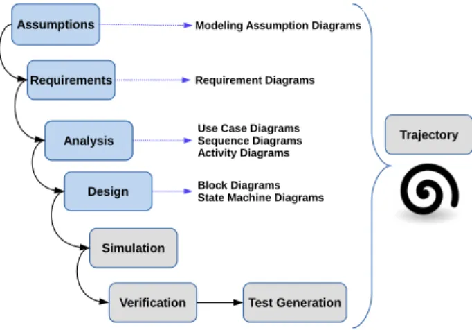
TTool [28] customizes SysML [21] to meet the needs of real-time systems modeling, addressing a specific part of systems development where the most important problem concerns matching the behavior of cooperating dynamic systems (at least one of which is a computer system) [17]. TTool has been associated with a methodology that applies to a broad variety of real-time systems. Modeling with SysML and TTool is an incremental process that starts with a very simplified model and progressively alleviates modeling assumptions to come up with a more realistic model. Each iteration in the incremental process follows the trajectory depicted by Figure 1.
• Assumptions capture. Modeling Assumptions Di-agrams are not part of the SysML standard, but are a TTool extension. They describe the set of assump-tions under which a system model is valid [24]. • Requirement capture. User and stakeholder
re-quirements are captured and related in requirement diagrams.
• Analysis is use case driven. A use case diagram is
documented by scenarios (sequence diagrams) and flow-charts (activity diagrams).
Assumptions Requirements Analysis Analysis Design Simulation
Verification Test Generation
Trajectory Modeling Assumption Diagrams
Requirement Diagrams
Use Case Diagrams Sequence Diagrams Activity Diagrams Block Diagrams State Machine Diagrams
Fig. 1: Design Trajectory
• Design defines the architecture of the system in the
form of a block instance diagram 1. Each block has a behavior expressed with a state machine diagram. The simulator of TTool animates SysML design dia-grams and enables early debugging of SysML models. The model checker and the verification by abstraction module of TTool deeply explore the behavior of the SysML model, as soon as the state space of the latter is of reasonable size. Next sections step-wise apply the method to the UAV in charge of taking pictures.
III. Case Study
Recent technological advances have allowed enormous progress in the development of UAVs. In the current case-study, we focus on drones. Recent advances in drone technology allow for more and more complex tasks to be performed, for example the use of drones for autonomous inspection purposes. For instance, Nokia suggests to use drones to inspect towers, test line of sight and plan radio sites with as goal the optimization of the telecommunica-tion networks [18]. Boeing also investigates the usage of drones for inspections [8]. The use of drones for inspection of buildings during the construction process for example is being studied, with as main goals to improve time efficiency, to insure workers safety, and to automate as much as possible the process [5]. Other examples include monitoring sites, carrying out delicate operations with dangerous/toxic products, delivering packages, etc.
In this paper, attention is focused on the use of drones for inspection activities taking pictures of specific objects. Such drones can be equipped with an embedded intelli-gence allowing them to decide in real time the path to take, which pictures to take, how to take them, when and how to avoid (or bypass) fixed or moving obstacles. Moreover,
1Unlike standard SysML, the version of SysML supported by
TTool does not distinguish between Block Definition Diagrams and Internal Block Diagrams. This is fully convenient for the style of systems we have been working on: one instance of each block is sufficient. Therefore we may merge the block definition and the block instance.
the drone operates in an environment containing unpre-dictable factors and communicates constantly with various information sources.
The UAV should be able to take off autonomously, fly in a stabilized way, and land at a specified destination or whenever a critical situation is encountered. The main focus here is that the UAV should take pictures at specified locations. Without loss of generality, taking off, route planning, obstacle avoidance, flying and landing actions are not considered here. Only the software related to taking pictures is modeled.
The above paragraph specifies the requirements associ-ated with the UAV controller.
Pictures can be taken only when the drone is flying. A remote control system located in a ground station can send “take picture” orders to the drone. A picture order contains the GPS position of the location where a picture has to be taken. To know its current position, a drone has an integrated GPS. When a picture location GPS point is reached, with regards to a given threshold, the picture is taken, and then stored on a CompactFlash removable storage system. The system needs 2 seconds to take a picture, and between 4 and 5 seconds to store it in on a CompactFlash memory. Pictures may be remotely down-loaded from the ground station using a download order. Pictures can also be read directly from the CompactFlash memory once the drone has come back from its mission.
IV. Modeling Assumptions and Requirements Capture
A. Modeling Assumptions
Experience has shown that models, in the same ways as this applies to software code, are scarcely self-contained and need to be documented to facilitate their sharing and reuse. In particular, when someone does not have information about the simplifications made by the designer of the model, or more generally, the assumptions made, it becomes hard to understand the model as is. For this reason, the authors of the paper advocate for an explicit inclusion of modeling assumptions inside the SysML model of the system. A Modeling Assumption Diagram (MAD), which is not part of the standard SysML definition [21], has accordingly been introduced into the version of SysML supported by TTool [24].
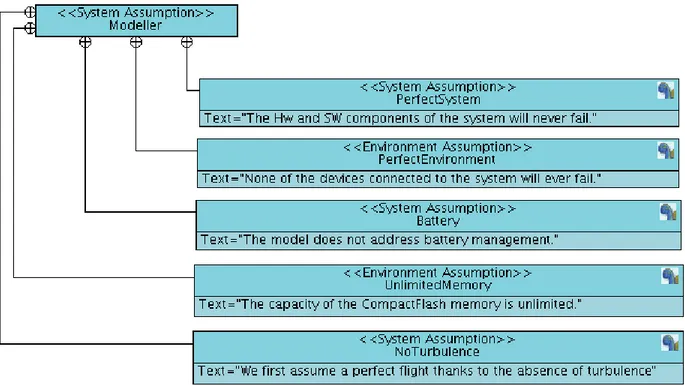
In terms of syntax, a MAD defines a tree-structure of boxes that contain the modeling assumptions. Pairs of boxes may be linked to semantically associate two assumptions. In Figure 2, the containment depicted by a cross inside a circle allows one to split up a complex assumption into elementary ones.
Like many SysML models published in papers and books, the model discussed in this paper ignores the set-up, shutdown and maintenance of the system. Unlike the same paper and books, this paper clearly address these limitations inside the SysML model using a Modeling Assumption Diagram (Figure 2). Another designer can easily trace down the reasons for these exclusions.
3
Fig. 2: Modeling Assumptions Diagram representing what the model leaves apart
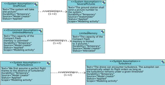
Since the method associated with TTool is incremental, assumptions may evolve at each iteration. Consequently, different modeling versions can be explicitly captured with MADs. Figure 3 exemplifies this with two UAV versions captured within the same SysML model. A first version of the model assumes the UAV takes one picture, whereas version 2 allows the ground station to set the number of pictures taken by the UAV. In addition, the first version of the model considers the CompactFlash memory has an unlimited storage capacity, whereas version 2 of the model decreases the memory capacity up to three pictures only. Finally, versions 1 and 2 of the UAV model differ by air turbulence handling or not.
B. Requirement Capture
The goal of system architecture activities is to define a complete solution based on principles, concepts and properties logically related and consistent with each other. Such solution should have suitable characteristics and properties, matching as well as possible to the problem expressed by a set of system requirements, traceable to mission/business and stakeholder requirements, and trace-able throughout life cycle phases and corresponding engi-neering tools (e.g. mechanical, electronics, software). This underlines the necessity to obtain pertinent requirements and explains why SysML supports requirement diagrams, a type of diagram not taken on board by UML [20].
Usual tabular representations of requirements merely list the latter and possibly organize them into chapters. Since SysML is a language and not a method, there are no constraints on writing style of requirements. In con-trast, an advantage of requirement diagrams as available
in SysML is to encourage system designers to structure and organize the requirements, and to show how the latter relate to other modeling elements of other diagrams. Each requirement node depicted by a box contains one requirement together with its unique identifier, a text, and a categorization between functional and non-functional requirement.
Finally, SysML organizes requirements in a tree struc-ture where pairs of requirements nodes are connected by either of the following relations:
• Containment. An arrow terminating by a cross and surrounded by a circle allows one to split up a high level requirement into elementary ones.
• Refinement. The « refine » relation from R1 to R2 allows R2 to add more precision to R1.
• Derivation. The « deriveReqt » relation from R1 to R2 allows R2 to bring a technical solution to functional requirement R1.
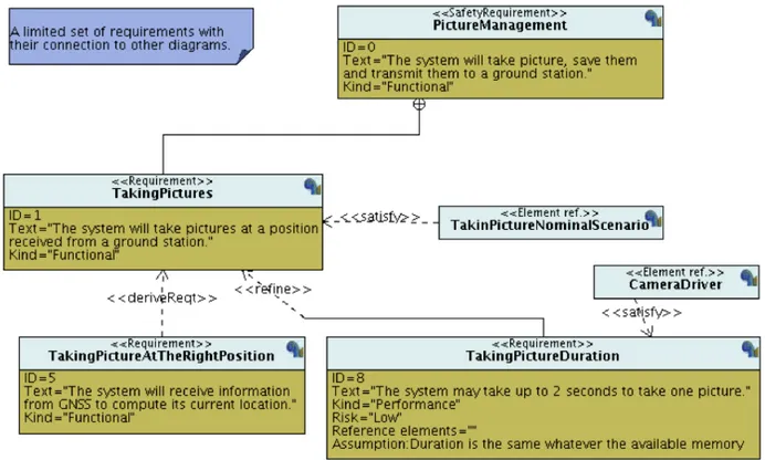
Figure 5 extracts requirements from Figure 4 and uses the «satisfy» relation to link these requirements to other diagrams belonging to the same SysML model. TakingPicture is linked to the sequence diagram (Fig-ure 5) developed during the analysis step of the trajectory introduced in Section 2. TakingPicture is linked to a state machine diagram developed during the design step of the method depicted by Figure 5.
V. Analysis and Design
A. Analysis
Creating a SysML diagram is a matter of decision-making. One of the major decisions the model designer has to take is to clearly delimit the perimeter of the system
<<versioning>> {1->2} <<versioning>> {1->2} <<versioning>> {1->2} <<System Assumption>> NoTurbulence Text="We first assume a perfect flight thanks to the absence of turbulence" Durability="Temporary" Source="Model creator" Status="Applied" Scope="Modeling activity" <<System Assumption>> Turbulence
Text="The drone can encounter turbulence. The autopilot can automatically adapt its flight orders as long as
the turbulence remains under a given threshold" Durability="Temporary" Source="Model creator" Status="Applied" Scope="Modeling activity" <<Environment Assumption>> UnlimitedMemory Text="The capacity of the Compact Flash memory is unlimited" Durability="Temporary" Source="Model creator" Status="Applied" Scope="Modeling activity" ... LimitedMemory Text="The capacity of the Compact Flash memory is limited to 3 pictures." Durability="Temporary" Source="Model creator" Status="Alleviated" <<System Assumption>> OnePicture Text="The system will take one picture" Durability="Temporary" Source="Model creator" Status="Applied" <<System Assumption>> SeveralPictures Text="The ground station shall send a picture number to the system."
Durability="Temporary" Source="Stakeholder" Status="Applied" Scope="Modeling activity"
Fig. 3: Modeling Assumptions Diagram developed to manage versioning
<<deriveReqt>> <<refine>> <<deriveReqt>> <<refine>> <<satisfy>> <<satisfy>> <<Requirement>> PictureProcessingSoftware ID=0
Text="The system shall take pictures, save them and transmit them to a ground station."
<<Requirement>>
TakingPictures ID=1
Text="The system shall take pictures at a position received from a ground station."
Kind="Functional"
<<Requirement>>
SavingPicture ID=2
Text="The system will save pictures to make them readable when the drone has come back from its mission."
<<Requirement>>
CompactFlash ID=21
Text="The system shall save pictures on a compact flash memory." Kind="Functional"
<<Requirement>>
TransmittingPictures ID=3
Text="The system shall transmit images to a ground station upon reception of a download order."
<<Requirement>>
TakingPictureAtTheRightPosition ID=11
Text="The system will receive information from GNSS to compute its current location." Kind="Functional"
<<Requirement>>
TimeToStore ID=211
Text="The flash shall take 4 to 5 seconds to store one picture."
Kind="Non-functional"
<<Requirement>>
TakingPictureDuration ID=12
Text="The system shall need 2 seconds to take one picture."
Kind="Performance"
<<Element ref.>>
EISCDesign_Camera
<<Element ref.>>
EISC216_Design_CompactFlash
Fig. 4: Requirement Diagram for the UAV
he or she intends to design and possibly to develop. The use case diagram, a pillar use case driven analysis, helps to assist the model designer in this task.
The first action the use case diagram creator has to take is to draw a rectangle characterizing the boundary of the system. What the designer puts inside the rectangle is what he or she sets out to design and develop. What he or she places outside the rectangle refers to the environment of the system and, clearly, designing the environment is not part of the duties of the SysML model’s creator.
In terms of SyML syntax, the rectangle contains a set of ovals that materialize the uses-cases containing the high-level functions and services to be offered by the system. Part of these functions makes the system interact with its surrounding environment and the existence of these interactions is depicted by links connecting the use cases to a set of actors belonging to the environment. Other types of links express relations between pairs of use cases located inside the rectangle that delimits the boundary of the system.
The use case diagram identifies the main functions and
services to be offered by the system. A common mistake is to create a use case that is not a high-level function, but an elementary one. If one considers a drink machine controller, a correct use case may be Process Payment. Compute Money or Return Change Back are elementary actions one should not be developed in a use case diagram but within an activity diagram documenting a use case.
On the other hand, the name of the use case, usually characterized by a verb, must convey the point of view of the system, not the point of view of the actors. Again, for a drink machine controller, Process Payment conveys the point of view of the system (the controller) whereas Insert Coin would convey the point of view of the user of the coffee machine.
Figure 6 depicts the use case diagram developed for the UAV model taking into account the above mentioned rules. The diagram uses «include» relations between pairs to denote function inclusions: for instance, ManagePicture necessarily includes two auxiliary functions to take and send pictures, respectively.
5
Fig. 5: Requirements Linked to Other Diagrams
<<include>> <<include>> <<Actor>> Autopilot PictureProcessingSystem <<Actor>> CompactFlash SendPicture SavePicture TakePicture <<Actor>> Camera ManagePosition <<Actor>> GNSSdevice <<Actor>> GroundStation
Fig. 6: Use Case Diagram
of the system interact with the outside environment, it does not specify the type of messages or signals the system uses to interact with the actors belonging to its environ-ment. That role is dedicated to the sequence diagrams that we use to document use cases in the form of scenarios.
Figure 7 depicts the scenario developed for the UAV model and more precisely for the first version of that model. Consequently, Figure 7 depicts a nominal sce-nario for a perfect system and a perfect environment. At this point, the two limitations (battery and memory capacity) are not taken into account. The first version
of the UAV (Figure 7) takes exactly one picture. The sequence diagram shows how the UAV receives an order from the ground station, checks its current position against the required position and corrects its location, takes one picture, saves and transmits it to the ground station.
A sequence diagram represents one possible execution scenario, while emphasizing on the exchanges between the system and its environment (i.e. the interfaces of the system under design). In no way it is intended to represent the entire behavior of the system, nor to list all the messages exchanged between the system and its environment, or the messages exchanged inside the system. The complete list of exchanged messages will appear on the architecture modeled during the design step.
Nevertheless, developing one or several sequence dia-grams helps model designers bridging the gap between the use case diagram and architectural design, given the former and the latter are functional and object-oriented, respectively. Further, the sequence diagram allows discus-sions with stakeholders. Last but not least, scenarios can be later reuse as reference scenarios to be played during testing.
Experience from teaching the use of SysML shows that several conceptual issues are not always easy to grasp for students. SysML textbooks and tutorials usually recom-mend a four-step process to create a use case diagram:
1) define the boundary of the system;
2) identify the actors as external entities that interact with the system;
3) identify the use cases from the goals of the actors; 4) establish the connections between actors and use
flight takePictureOrder(100,100) gotoToPosition(100,100) currentPosition(98,98) takePicture PictureWasTaken(pic) {2..2} savePicture(pic) PictureWasSaved {4..5} transmitPicture() picture(pic) readPicture() pictureData(pic) currentPosition(99, 99) currentPosition(100, 100)
GroundStation GNSSDevice CompactFlash PictureProcessingSystem
CorrectLocationReached
Camera
Human Operator sends the coordinates of the place where the drone must take pictures.
Human Operator initiates the procedure.
Autopilot
ComputeSpeedAndDirection
Fig. 7: Sequence Diagram
cases, and set up relations between pairs of use cases. Usually this methodology is illustrated using a simple system. However, such illustrations do not avoid beginners to be confused when in front of a screen or in front of a white piece of paper. Where to start? Studies conducted with students allowed to identify difficulties with choosing the right type of relationship, defining the direction of the extend relationship and proper naming of elements [35] [36]. These results were confirmed by our own experience. An important problem for students is to appreciate what is supposed to be inside the box and what is supposed to be outside (i.e. what is part of the system to be developed and what is an external role). Our experience has shown this to be a real blocking point, leading to students mixing up internal and external roles. Maintaining the use cases at the right level and not confusing high-level functions and elementary actions is a major difficulty. Such a confusion might lead to an unbalanced design of the system, mixing main functions and implementation details. Other com-mon beginners’ errors may include the absence of verbs in use case names and the use of proper names for actors rather than a common name representing a role.
B. Design
The design step first addresses a fundamental issue: elaborating and fixing the architecture of the system. In SysML, the architecture remains a static structure depicting the system as a set of interconnected “boxes”. Adding state-machine diagrams to the model enables de-scribing the inner workings of the architecture blocks. This ”executable” model can thus be simulated and verified taking into account both its architecture and its behaviour. With SysML, the systems engineering community has developed its own modeling language. At the same time,
the choice was made to propose SysML as a UML pro-file. Therefore, SysML de facto reuses the object-oriented principles of UML even at the price of renaming «class» by «block» and describing systems architectures by block diagrams2 instead of class diagrams.
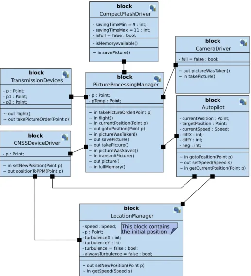
The standardized version of SysML uses two architec-tural diagrams: the block definition diagram (BDD) and the internal block diagram (IBD). By contrast, the version of SysML supported by TTool suggests to merge them in one architectural diagram when the system is simple e.g. there is one instance per block: this is the case of the block diagram depicted by Figure 8. Note: The use case diagram depicted by Figure 6 clearly identifies the boundary of the system to be designed. The architecture elaborated at the design step should therefore be lim-ited to one block named PictureProcessingSystem. The PictureProcessingSystem block cannot be simulated if the signal input actions and signal output actions of its state machine are not respectively triggered by output sig-nal actions and input sigsig-nal actions of the state machines embedded in blocks that model the actors. In practice the later are designed to accept all the signal emissions and signal receptions offered by PictureProcessingSystem. This explains why Figure 8 depicts a simulation-oriented architecture with seven blocks instead of one.
The architecture of Figure 8 lists the signals respectively accepted and emitted by the blocks. The way of creating input and output signals can be sketched as follows. We first introduce signals characterizing communication be-tween the system (here, PictureProcessingSystem) and
2Blocks are to be defined in ”Block Definition Diagrams” and
blocks are to be instantiated and connected in ”Internal Block Diagrams”
7 <<datatype>> Point - x : int; - y : int; <<datatype>> Speed - x : int; - y : int; block CameraDriver - full = false : bool; ~ out pictureWasTaken() ~ in takePicture() block Autopilot - currentPosition : Point; - targetPosition : Point; - currentSpeed : Speed; - diffX : int; - diffY : int; - neg : int; ~ in gotoPosition(Point p) ~ out setSpeed(Speed s) ~ in getCurrentPosition(Point p) block GNSSDeviceDriver - p : Point; ~ in setNewPosition(Point p) ~ out positionToPPM(Point p) block PictureProcessingManager - p : Point; - pTemp : Point; ~ in takePictureOrder(Point p) ~ in flight() ~ in currentPosition(Point p) ~ out gotoPosition(Point p) ~ in pictureWasTaken() ~ out savePicture() ~ out takePicture() ~ in pictureWasSaved() ~ in transmitPicture() ~ out picture() ~ in fullMemory() block CompactFlashDriver - savingTimeMin = 9 : int; - savingTimeMax = 11 : int; - isFull = false : bool; - isMemoryAvailable() ~ in savePicture() block TransmissionDevices - p : Point; - p1 : Point; - p2 : Point; ~ out flight() ~ out takePictureOrder(Point p) block LocationManager - speed : Speed; - p : Point; - turbulenceX : int; - turbulenceY : int; - turbulence = false : bool; - alwaysTurbulence = false : bool; ~ out setNewPosition(Point p) ~ in getSpeed(Speed s)
This block contains the initial position
Fig. 8: Architecture of the UAV - Block Instance Diagram
its environment. The first list of signals directly stems from the signals identified by sequence diagrams.
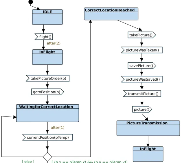
A state machine diagram depicts an extended fi-nite state machine that may handle states, data, and time. Figure 9 depicts the state machine associated with PictureProcessManager block. The state machine han-dles state changes, tests several attributes of the block (see p.x), receives signals (e.g., see flight for a reception), and emits signals (e.g., see gotoPosition(p) for a recep-tion). One transition has an after(1,1) label modeling a computation time.
The state machine depicted by Figure 9 gives the Memory Recorder one behavior and makes it executable, a premise to applying model simulation techniques.
VI. Model Simulation
A. Principles
The Simulator of TTool enables animation of state machine diagrams. It takes as input syntactically and type-checked SysML models and computes the initial global state of the design model. Step by step firing of transitions enables early debugging of the models by joint observation
of simulation traces in the form of sequence diagrams, annotations on the SysML models themselves and display of the state, variables and other elements contained in the blocks the system is made up of. Random firing of transi-tions enables exploring the behavior of the system until a deadlock situation or a termination state is encountered.
B. Application to the UAV
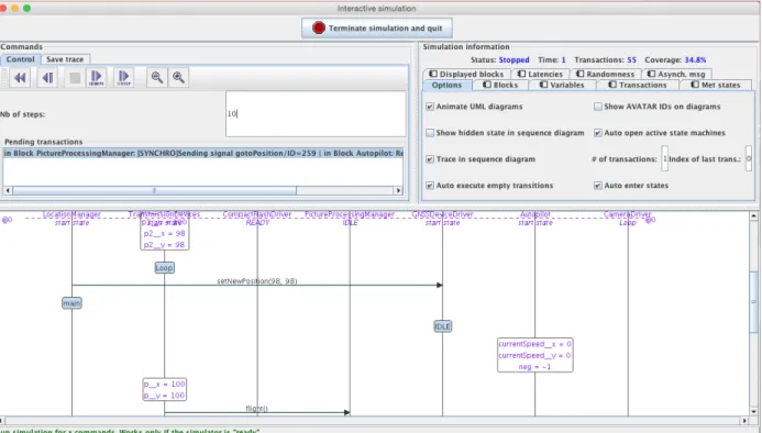
The screenshot in Figure 10 shows the first steps of the UAV model simulation. TTool outputs the simulation trace in the form of a sequence diagram that can be manually compared to the sequence diagrams and to other diagrams elaborated in the previous steps of the trajectory. Figure 11 depicts an animated version of the state ma-chine of the CompactFlashDriver block. One may identify which transitions have been fired by the simulator.
The simulator of TTool is of great help for early debug-ging of the SysML models, finding out incorrectly initial-ized variables, and unexpected message receptions. Joint use of simulation traces and annotated state machines offers two complementary angles to interpret the way the model of the system progresses in terms of message
currentPosition(pTemp) gotoPosition(p) takePictureOrder(p) takePicture() pictureWasTaken() savePicture() pictureWasSaved() transmitPicture() picture() IDLE flight() InFlight WaitingforCorrectLocation CorrectLocationReached InFlight PictureTransmission
[ (p.x == pTemp.x) && (p.y == pTemp.y)] after(2)
after(1)
[ else ]
Fig. 9: State Machine Diagram for PictureProcessingManager block
exchanges and time progression, the latter usually being something difficult to apprehend when one starts learning using such tools.
Simulation allows one to explore particular (or random) execution paths in the state space of the global system. Simulation heavily depends on the expertise of the model creator in terms of capacity to pick the most relevant exploration paths. Formal verification, which is the subject of next section, is a much more systematic approach.
VII. Model Formal Verification
A. Properties
The simulator of TTool randomly explores potential behaviors of the system where formal verification relies on mathematics rather than chance. Numerous formal verification approaches have been proposed ranging from verification of systems models to program proof. All of them capture a preliminary problem phrased by the fol-lowing question: ”Which properties do you want verify on your system or program?”.
Answering that question is not an easy task. Experience in teaching SysML has regularly confirmed that point.
To help students, we give hints by categorizing properties into general and specific properties. We further distinguish between safety and liveness properties.
• General properties are the ones to be satisfied by a broad variety of systems, if not all systems. Examples include deadlock freeness, livelock freeness, and capacity to return to initial state.
• Specific properties are proper to the system un-der design. For a microwave oven, ”The heating pro-cess cannot start as long the door remain open” is a specific property. For Pilot to Air Control Tower communication, ”Each request from the pilot will be acknowledged by the Controller within 3 seconds” is also a specific property.
• Safety properties express that the systems can reach regular state but cannot reach error states. For instance, the state ”Oven opened and heat on” should not be reachable in a microwave oven.
• Liveness properties relate to actions or states that are eventually reached, i.e. reached what ever the execution of the system. For instance, when the heat of microwave is started, it should eventually reach a
9
Fig. 10: Simulation Trace
1 Loop 1 takePicture() 1 pictureWasTaken() after (2, 2) 1 1
Fig. 11: Following up Simulation on a State Machine
heat-off state.
Depending on the properties to be verified, users of TTool are offered three complementary techniques:
• reachability analysis, • model checking, and • verification by abstraction.
B. Reachability Analysis
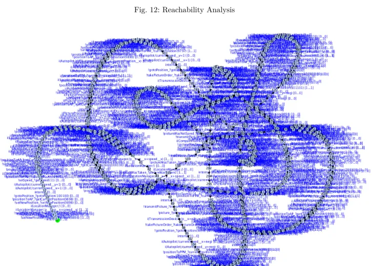
Relying on a systematic analysis of the state space of the system under design, reachability analysis outputs a reachability graph representing all the valid execution paths and states of the system starting from its initial state. Figure 13 shows one possible representation for this graph. Obviously, a graph with 671 states and 923 transitions cannot be analyzed by hand in a reasonable time. Next sections bring solution to automate analysis.
It may happen the reachability graph of the model can-not be computed because of the state explosion problem. This not the case for the UAV that serves as running example throughout this paper.
C. Model Checking
1) Principles: In [34], Fisman and Pnuelli define model
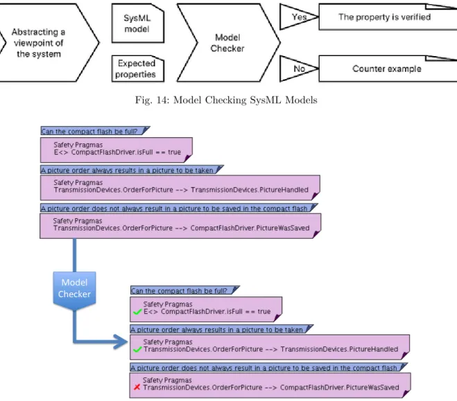
checking as the method by which a desired behavioral property of a reactive system is verified over a given system (the model) through exhaustive enumeration (explicit or implicit) of all the states reachable by the system and the behaviors that traverse through them. Figure 14 pic-torially identifies three main steps. The model checker is catered with a model of the system and a formal expres-sion of the properties to be verified. The model checker processes the model and the properties, and outputs a ”yes/no” answer stating whether the property is verified or not. The model checker also traces execution paths that leads to property violations. The tool must indeed help the designer of the system interpreting verification results in the light of the model of the system the tool was catered with.
2) Accessibility of states and actions in the state ma-chines: No need to write pragmas
3) Safety Pragmas: A safety pragma lists one or several
properties expressed as follows. Basically, a property p is written as: p = A|E []| <> P or p = P 1 − − > P 2 with:
• A means that the property P shall apply to all
paths starting from the initial state of the reachability graph.
Fig. 12: Reachability Analysis
Fig. 13: Reachability Graph of the UAV Model
• E means that the property P shall apply to at
least one oath starting form the initial state of the reachability graph.
• [] means that the property P shall apply to all state of the path.
• <> means that the property P shall apply to at least
one state of the path.
• −− > is the ”leads to” operator stating that P1 must eventually be followed by P2. Thus, if P1 is true is a given state s of the reachability graph, P2 must be true in at least one state in all paths starting from s. As an example, let us consider the safety pragmas given in figure 15:
• A[]Autopilot.currentSpeed x >= Autopilot.neg
means ‘In all states of the reachability graph cur-rentSpeed x of Autopilot is always greater or equal to the neg attribute of Autopilot’
• E <> CompactF lashDriver.isF ull == true means
‘There exists at least one state where the attribute isFull of block CompactFlashDriver is equal to true’
• P ictureP rocessingM anager.W aitingf orCorrectLocation−
− > P ictureP rocessingM anager.CorrectLocationReached means that ‘Whevener the waitingForCorrect-Location state of PictureProcessingManager is reached, then the state CorrectLocationReached of PictureProcessingManager is eventually reached’. Said differently, the UAV always manages to reach a requested waypoint.
Pragmas of the case study are given in Figure 15. The internal model-checker of TTool is called to compute the satisfaction of each pragma, and then results are backtraced to diagrams, as shown in the lower part of the figure. Alternatively, UPPAAL [30] can be called from TTool to evaluate safety pragmas.
11
Fig. 14: Model Checking SysML Models
Fig. 15: Checking Safety Pragmas
D. Verification by Abstraction
From a theoretical point of view, verification by ab-straction reuses theories developed for Labeled Transition Systems (LTS) [16]. Referring again to communication systems, the reachability graph of the SysML model is transformed into a LTS. Each transition involved in trans-mitting a signal linked to the valued added service is labeled by the name of the signal. Other transitions are labeled by ‘nil’. The resulting labeled reachability graph is minimized with the purpose of eliminating the transitions labeled by ‘nil’. The output of the minimization is termed as ‘quotient automaton’.
A user can select actions of interests (dialog window of the left, actions can be ignored of selected) and then obtain a minimized graph as show on the right of Figure 16.
For instance, the designer of the UAV model may decide to limit the view of the system to receiving instructions from the ground station, taking one picture, saving it on memory and transmitting it to the ground station. He or she selects the signals to be preserved accordingly. From a reachability graph of 674 states and 927 transitions, he or she obtains a quotient automaton of 17 states and 19
tran-sitions. Because of its size, the quotient can be analyzed by human eye. It further characterizes the service offered by the drone management system. Therefore verification by abstraction pretty well applies to layered design of systems [25].
VIII. Lessons learned
This section sums up the lessons learned in teaching SysML over the past decade and using the UAV addressed in this paper amongst others as educational case study.
A. Software Engineering Background
SysML has been designed with systems modeling in mind and, consequently, its use cannot be envisioned outside of a coherent system engineering curriculum. The authors of this paper strongly believe that SysML courses should be preceded by a system engineering course.
First, to make the student familiar with the concept of life cycle, and to prepare him or her to understand when specific SysML diagrams must be used (e.g. for use case driven analysis).
Fig. 16: Verification By Abstraction
Second, the system engineering course should include a ”Writing good requirements” chapter. As a matter of fact, SysML being a notation and not a method, the SysML standard does not define the way of writing the ”text” field that enables encapsulation of requirements inside ”boxes” stereotyped by «Requirement» in the requirement diagram.
Third, the system engineering course should include a chapter on architectural design and validation, particu-larly focusing on interface definition and layered design.
B. Abstractions
Making abstractions at the right abstraction level is the keystone of modeling activity. The use of SysML raises several problems with this respect.
Difficulties also arise with time management in both the SysML model and the simulator of TTool. Each transition contains a clause ‘after (Tmin, Tmax)’ to say the transi-tion may not fire before Tmin units of time after being enabled (e.g. by a message reception) and no later than Tmax units of time after the transition was enabled. By default: Tmin = Tmax = 0. The simulator implements a firing transition policy where the transitions whose Tmin and Tmax clauses are different from 0 cannot be fired before all transitions fireable at t=0 are fired.
C. Incremental modeling
It is fundamental to explain the students not to try building up a complete model before starting any simu-lation or verification session. It is preferable to follow an incremental process, thus starting with a core model that strongly simplifies the system and progressively alleviates the modeling assumptions to create more realistic models and eventually completes the modeling process that is sufficiently detailed.
D. Inter-diagram Consistency
A SysML model is usually made up of several diagrams. Like the UML language it roots in, SysML raises the following question: given a model M, how to maintain consistency between the many diagrams included in M?
Considering a use case diagram documented by one or several sequence diagrams, making the sequence diagrams consistent with the use case diagram particularly requires to not create inside the sequences diagrams an actor that does not appear in the use case diagram. TTools offers a solution to achieve that goal: it enables generating lifelines of sequence diagrams from a use case diagram. This is an example of synthesizing a new diagram from an existing one and this is also an example of facility offered by TTool, not by other SysML tools. The offer will remain limited because some synthesis problems remain undecidable in the general case, for instance, generating an architecture of block diagrams from a collection of sequence diagrams.
E. Learning by example
Students (but maybe also engineers) often build new models by ”imitation” of existing ones. The friendliness of a SysML tool not only depends on its user-interface, but also on a library of sample models provided with that tool. It is further important to work on use case, architectural and behavioral patterns.
IX. Related Work
This section surveys related work on two issues ad-dressed by this paper: usage of SysML for UAV modeling and formal verification of SysML models. Discussion is then extended to detailed design in SysML in association with SysML.
A. SysML and UAVs
In [41] Gadelha et al. advocate for joint use of Product Line Engineering (PLE) and Model-Driven Engineering (MDE) approaches to develop families of UAVs. SysML and MARTE are jointly used to support requirements specification, design, validation, and simulation. Code gen-eration is also included. The Common Variability Lan-guage (CVL) is used to transform generic product line models into specific product models, which increases the degree of reuse.
In [40] Steurer et al. present a SysML profile, i.e. a customization of the SysML language, termed as ‘UDP’,
13
an acronym for ‘UAV Dependability Profile.’ The paper proposes a methodology that integrates dependability analysis within a MBSE approach in early phases of the system development. The methodology associates Dual graph Error Propagation Model (DEPM) and SysML-based structural modeling of mechatronic systems.
In [42] Ballard et al. acknowledge the benefits of using MBSE to formalize interactions between subsystems in the design process, thus easing the transfer of informa-tion between parties. In particular, diverse requirements must be altered and tracked between the requesting, re-sponding, and evaluating parties. The paper demonstrates modeling patterns and a tool that translates information from native-model form into a text-based format. It also presents tools to support source selection process of the acquirer. Making use of the patterns - the sources from which requirements text is generated, Evaluation and Esti-mation Models are also presented: they can act directly on the responses from the contractors. The Evaluation Model assists the verification process by ensuring numerical re-quirements are satisfied. The Estimation Model compares the values claimed by the contractors with historically expected values, in order to support the focus of examina-tion for the source selecexamina-tion experts. A fourth tool offers a method of extracting historical traceability for model elements.
B. Formal Verification of SysML Models
In [39], Gabmeyer et al. have proposed a taxonomy of formal verification techniques for software models. In this section, discussion focuses on recent papers addressing simulation and formal verification in the context of SysML. In this paper, simulation, reachability analysis and model checking are applied to design diagrams, namely block diagrams that model the architecture of the system and state machine diagrams that model the inner workings of the blocks. Other authors have addressed simulation and formal verification based on scenarios expressed in the form of sequence diagrams or flow-chart depictions of activities based on activity diagrams.
In [38], Ouchani et al. present a formal verification framework for checking of SysML activity diagrams. The latter are mapped into the input language of the proba-bilistic model checker PRISM. A calculus dedicated to ac-tivity diagrams is proposed and the mapping to PRISM si formalized. The approach is applied to an online shopping system and to real time streaming protocols.
C. SysML and Detailed Design in Simulink
In this paper, modeling is achieved at system level and so is formal verification of SysML models. Other papers have associated SysML modeling at system level with detailed design in Simulink.
In [12], Liu and Cao associate the SysML tool Rhapsody with Simulink to design a UAV flight control system. Rhapsody enables simulating the discrete/event part of
the system behavior but misses a continuous-time simu-lator. This is why Simulink is used for. Accordingly Liu and Cao essentially discuss the use of SysML blocks and SysML state machines, and briefly survey other diagrams. Associating a SysML tool and Simulink has also been discussed in the context of test sequence generation. In [37], Gonzales et al. propose a SysML-based modeling methodology for model testing of CPSs, and a SyML-Simulink co-simulation framework.
X. Conclusions
Unmanned vehicles fall in the category of systems that capture complex design problems and question the ben-efits and potential of Model-Based System Engineering approaches. How to make a language, a tool and a method accepted by UAV designers is a really challenging issue.
This paper advocates for a MBSE approach based on SysML, the widely adopted standard throughout industry for system modeling. Unlike papers that limit the use of SysML to a industrial drawing, this paper proposes to use the free software TTool to consider SysML models for early detection of design errors in the life cycle of a UAV. SysML models are debugged using the simulator of TTool and more systematically explored using two com-plementary formal verification techniques: model checking and verification by abstraction.
Acknowledgement
The authors would like to acknowledge the support of Luc M¨uller–Ripalda in the early phases of this manuscript.
References
[1] Agarwal, B., Transformation of UML Activity Diagrams into Petri Nets for Verification Purposes, International Journal of Engineering and Computer Science, vol. 2, no.3, pp. 798-805. [2] Andersson, H, Herzog, E, Johansson G., Johansson, O.,
Ex-perience from introducing Unified Modeling Language/Systems Modeling Language at Saab Aerosystems, Vol. 13, Issue 4, Winter 2010, pp. 369-380.
[3] Apvrille, L., Saqui-Sannes, P. de, Requirements Analysis, Book chapter in Embedded Systems: Analysis and Modeling with SysML, UML and AADL, Edited by F. Kordon, J. Hugues, A. Canals and A. Dohet, Ed. ISTE /Wiley, May 20, 2013, ISBN-13: 978 1848215009.
[4] Arantes, M., Bonnard R., Mattei A.-P., Saqui-Sannes P. de, General Architecture for Data Analysis in Industry 4.0 using SysML and Model Based System Engineering, 12th Annual IEEE International Systems Conference (SysCon 2018), April 2018, Vancouver, BC, Canada.
[5] R. Ashour et al., Site inspection drone: a solution for inspecting and regulating construction sites, IEEE 59th International Mid-west Symposium on Ciruits and Systems, 16-19 October, Abu Dhabi, 2016.
[6] Baduel, R., Chami, M., Bruel J.-M., Ober I., SysML Models Verification and Validation in an Industrial Context: Challenges and Experimentation, European Conference on Modeling Foun-dations and Applications (ECMFA 2018), LNCS, volume 10890, pp. 132-146.
[7] Blondelle, G., Bordeleau, F., Exertier, D., Polarsys: A New Collaborative Ecosystem for Open Source Solutions for Systems Engineering Driven by Major Industry Players, Insigight, Vol. 18, no.2, August 2015, pp. 35-38.
[8] V. Khumalo. Boeing uses drones for inspection. [Online, 2015]. Available: http://www.rocketmine.com/boeing-uses-drones-for-inspection/, last accessed April 17, 2018.
[9] Bone, M., Cloutier, R., The Current State of Model Based Systems Engineering: Results from the OMGâĎć SysML Request for Information 2009, 8th Conference on Systems Engineering Research, March 2010, Hoboken, NJ, USA.
[10] Fernandez J, Lopez, J., Patricio Gomez, J, Reengineering the Avionics of an Unmanned Aerial Vehicle, IEEE Aerospace and Electronic Systems Magazine, vol. 31, no. 4, pp. 6-13, April 2016. [11] Ifx-OMEGA, https://www.irit.fr/ifx/.
[12] X. h. Liu and Y. f. Cao, Design of UAV Flight Control System Virtual prototype using Rhapsody and Simulink, 2010 Interna-tional Conference On Computer Design and Applications, Qin-huangdao, 2010, pp. V3-34-V3-38.
[13] Kayal, I., Farid, A., The Need for Systems Tools in the Practical Of Clinical Medicine, Systems Engineering.
[14] Madni, A., Sievers, M., Model-based systems engineering: Mo-tivation, current status, and research opportunities, Systems Engineering, May 2018.
[15] Mattei, A-P., Loures, L., Saqui-Sannes, P. de, Escudier, B., Feasibility study of a multispectral camera with automatic pro-cessing onboard a 27U satellite using Model Based Space System Engineering, IEEE Systems Conference April 2017, Montreal, Qc, Canada.
[16] Milner, R., Communication and Concurrency, Prentice Hall, 1989.
[17] Motus, L., Time Concepts in Real-Time Software, IFAC Pro-ceedings Volumes, Vol. 25, Issue 11, June 1992, pp. 1-10. [18] L. Tung. Nokia puts telco drones to work inspecting cell towers.
[Online, 2015]. Available: http://www.zdnet.com/article/nokia-puts-telco-drones-to-work-inspecting-cell-towers/, last accessed April 17, 2018.
[19] UPPAAL, http://www.uppaal.org/.
[20] OMG, UML, Unified Modeling Language, December 2017, https://www.omg.org/spec/UML/2.5.1/.
[21] OMG, SysML, Systems Modeling Language 1.5, May 2017, http://www.omg.org/spec/SysML/1.5/.
[22] Ouchani, S., Ait Mohamed, O., Debbabi, M., 2014, A formal verification framework for SysML activity diagrams, Expert Sys-tems with Applications, (41) 6, pp. 2713-2728.
[23] Rhapsody, https://www.ibm.com/us-en/marketplace/architect-for-systems-engineers.
[24] Saqui-Sannes, P. de, Apvrille, L., 2016, Making Modeling As-sumptions an Explicit Part of Real-Time Systems Models, 8th European Congress on Embedded Real Time Software and Sys-tems (ERTS), Toulouse, France, pp. 27-29
[25] Saqui-Sannes, P. de, Vingerhoeds, R., Apvrille, L, EarlyCheck-ing of SysML Models applied to protocols, 12th International Conference on Modeling, Optimisation and Simulation (Mosim 2018), June 2018, Toulouse, France.
[26] Le Sergent, T, SCADE: A Comprehensive Framework for Crit-ical System and Software Engineering, International SDL Forum 2011, LNCS, volume 7083.
[27] TINA, http://projects.laas.fr/tina/. [28] TTool, https://ttool.telecom-paristech.fr/.
[29] Ullah, I., Tang, D. and Yin, L. (2015), Engineering Change Implications on Product Design: A Review of the Literature, International Conference on Education, Management and Com-puting Technology (ICEMCT-15), Atlantis Press, Tianjin, pp. 1679âĂŞ1691
[30] UPPAAL, http://www.uppaal.org/.
[31] Vernadat, F., Percebois, c., Farail, P., Vingerhoeds, R., Rossignon, Alain, Talpin J.-P., Chemouil D., The TOPCASED Project - A Toolkit in OPen-source for Critical Applications and SystEm Development, Data Systems In Aerospace (DASIA 2006), Berlin, Germany, ESA, May 2006.
[32] Wassem, M., Usaman Adiq, M., Application of Model-Based Systems Engineering in Small Satellite Conceptual Design: A SysML Approach, IEEE Aerospace and Electronic Systems Mag-azine, Vol. 33, Issue 4, April 2018.
[33] Wolny, S, Mazak, A., Carpella, C., Geist V., Wimmer, M., Thirteen Years of SysML: a Systematic Approach, Software and Systems Modeling, May 2019.
[34] D. Fisman and A. Pnueli, Beyond regular model checking, 21st conference on Foundations of Software Technology and Theoret-ical Computer Science, LNCS 2245, pp. 156170, 2001.
[35] H. Kruus, T. Robal, Tarmo, G. Jervan, Teaching modeling in SysML/UML and problems encountered, 25th EAEEIE Annual Conference (EAEEIE), 2014, pp. 33-36.
[36] J. Holt, S., Perry, SysML for systems engineering, IET, 2008. [37] C. A. GonzÃąlez, M. Varmazyar, S. Nejati, L.C. Briand,
Y. Isasi, Enabling Model Testing of Cyber-Physical Systems. ACM/IEEE 21th International Conference on Model Driven En-gineering Languages and Systems (MODELS 2018), New York, NY, USA, 2018.
[38] S. Ouchani, O. Ait Mohamed, M. Debbabi, A formal verification framework for SysML activity diagrams, Expert Systems with Applications, Vol 41, no6, May 2014, pp. 2713-2728
[39] S. Gabmeyer, P. Kaufmann,ÂůM. Seidl, M. Gogolla, G. Kap-pel, A feature-based classification of formal verification tech-niques forsoftware models, Software Systems Model (2019) 18:473âĂŞ498.
[40] M. Steurer, A. Morozov, K. Janschek, K.-P. Neitzke, SysML-based Profile for Dependable UAV Design, IFAC-PapersOnLine, Vol.51, No.24, pp. 1067-1074 (2018).
[41] P. G. Gadelha Queiroz, R. T. Vaccare Braga, Combining MARTE-UML, SysML and CVL to Build Unmanned Aerial Vehicles, ICSEA 2014 : The Ninth International Conference on Software Engineering Advances, Nice, France, October 2014.M. Ballard, A. Baker, R. Peak, S. Cimtalay, D. Mavris, Facilitating the Transition to Model-Based Acquisition, 2020.
[42] M. Ballard, A. Baker, R. Peak, S. Cimtalay, D. Mavris, Facili-tating the Transition to Model-Based Acquisition, 2020.