HAL Id: hal-01304007
https://hal.archives-ouvertes.fr/hal-01304007
Submitted on 19 May 2016
HAL is a multi-disciplinary open access
archive for the deposit and dissemination of
sci-entific research documents, whether they are
pub-lished or not. The documents may come from
teaching and research institutions in France or
abroad, or from public or private research centers.
L’archive ouverte pluridisciplinaire HAL, est
destinée au dépôt et à la diffusion de documents
scientifiques de niveau recherche, publiés ou non,
émanant des établissements d’enseignement et de
recherche français ou étrangers, des laboratoires
publics ou privés.
Proton Exchange Membrane Fuel Cell Operation and
Degradation in Short-Circuit
Rosa Elvira Sanchez, Fabien Harel, Samir Jemei, Rafael Gouriveau, Daniel
Hissel, Loïc Boulon, Kodjo Agbossou
To cite this version:
Rosa Elvira Sanchez, Fabien Harel, Samir Jemei, Rafael Gouriveau, Daniel Hissel, et al.. Proton
Exchange Membrane Fuel Cell Operation and Degradation in Short-Circuit. Fuel Cells, Wiley-VCH
Verlag, 2014, 14 (6), pp.894 - 905. �hal-01304007�
Proton Exchange Membrane Fuel Cell Operation and
Degradation in Short-Circuit
R.E. Silva1,2,3, F. Harel2,4, S. Jemeï1,2, R. Gouriveau1,2,5, D. Hissel1,2, L. Boulon3, and K. Agbossou3 1 FEMTO-ST Institute UMR CNRS 6174, Université de Franche-Comté, Techn’Hom 90010 Belfort
Cedex, France
2 FCLAB FR CNRS 3539, Techn’Hom 90010 Belfort Cedex, France
3 IRH, Institut de Recherche sur l’Hydrogène, Université du Québec à Trois-Rivières, Trois-Rivières,
Canada
4 IFSTTAR, Université de Lyon, 25 Avenue François Mitterrand, Case24, Cité des mobilités, F-69675
Bron Cedex, France
5 ENSMM, National Engineering Institute in Mechanics and Microtechnologies, 26 Rue de l’Épitaphe
25000 Besançon, France
Abstract
Hybridization of Proton Exchange Membrane Fuel Cells (PEMFC) and Ultra Capacitors (UC) are considered as an alternative way to implement high autonomy, high dynamic and reversible energy sources. PEMFC allow high efficiency and high autonomy, however their dynamic response is limited and this source does not allow recovering energy. UC appears to be a complementary source to Fuel Cell Systems (FCS) due to their high power density, fast dynamics and reversibility. A direct hybridization of these sources could allow reducing the number of power converters and then the total cost of the hybridized system. Simulations show the behavior of the hybrid source when the fuel cell and ultra capacitors are interconnected and the natural energy management when a charge is connected. The results show that the magnitude of the transient current supplied by the fuel cell to charge the UC can be much higher than its nominal value. An experimental setup is implemented to study the effects of these high currents in a PEMFC. This is done by imposing a controlled short-circuit between the electrodes. The PEMFC degradation is quantified by using electrochemical impedance spectroscopy.
Keywords: Degradation, Passive Hybridization, Proton Exchange Membrane Fuel Cells, Short-Circuit,
Start-up, Ultra capacitors
List of Symbols
f G
∆ Gibbs free energy released
Acd, Bcd Nernst potential coefficients
ν δ γ β α, , , , Empirical coefficients A, B Overvoltage coefficients Il Limit current /A In Internal current /A
Vc Dynamic part of the cell voltage / V EC
Sq
∆ Entropy flow due the exothermal electrochemical reaction / W K-1
2 H Sq ∆ , 2 O Sq
∆ Entropy flows between the stack and the gas. th
1
Introduction
Fuel cell systems (FCS), and in particular, Proton Exchange Membrane Fuel Cells (PEMFC) are interesting energy sources because of their high efficiency, low emissions and high energy density. However, the dynamic response of the FCS is limited by the gas supply and then the FCS are very constrained to supply high dynamic power loads, moreover FCS are not able to recover energy (regenerative braking in vehicular application for instance) [1-5]. Ultra Capacitors (UC) appear as an interesting complementary source to FCS due to their high power density, fast charge/discharge abilities, and reversibility [2, 5-7]. However, UC cannot be used as unique source because of their limited energy storage capability. Fuel cells in combination with ultra capacitors can be used for satisfying energy efficiency and dynamic response of applications such as vehicle traction where UC would enable recovering braking energy, and mitigates the stress on the fuel cell [8-10].
Fuel cell and ultra capacitors can be hybridized using either active or passive architectures. Active hybrid architectures require at least one DC/DC converter to perform energy management [5, 11-13]. The presence of the power converters generally increases the energy losses, the volume, the weight and the cost of the hybrid source [6, 12]. In passive hybrid architectures, the fuel cell and the ultra capacitors are directly connected to the DC bus without using a power converter [5, 11, 13]. In this architecture, the ultra capacitors absorb the excess power from the stack, not only allowing regenerative braking but also providing a fraction of transient power for vehicle acceleration [6, 10].
The passive hybrid configuration with direct bus connection is a cheap and simple solution; the power electronics losses are eliminated. Moreover the weight and the volume of the source are reduced and this can slightly increase the global efficiency [4, 9, 11, 13, 14]. However, the control of the power flow is not possible anymore.
Recent researches have studied the hybridization of UC and FCS. Garcia-Arregui et al., [6] analyse the characteristics of a passive hybridization of fuel cell and ultra capacitors. The authors propose an iterative global system sizing method to study the effect of the sizing in the natural energy management to obtain an adequate power distribution. Junbo et al., [3] study the electrical behavior of a PEMFC and UC passive hybrid source for a small vehicle (bicycle). The results suggest that the passive source can supply the load with high dynamics and uninterrupted power; it can also improve the efficiency, the peak power and extend the autonomy of the system. Moreover the UC reduces the dynamical power supplied by the fuel cell.
Zhao and Burke [10] compare FC/UC hybridization using different powertrain configurations, and power split control strategies. Based on fuel economy/consumption and component/system efficiency for the same size vehicles having the same road load characteristics, simulation results demonstrate that passive hybrid architecture increases the global efficiency mainly because of the elimination of the power electronics energy losses. Hinaje et al. [12] propose the implementation of a PEMFC as a current source controlled by hydrogen flow rate. The work mainly focuses on mass transport in the electrodes to describe the transient electrical behavior. This is done for FC/UC passive hybridization and PEMFC short–circuit. Fuel cell degradation has not been revealed after this experience. Recently, Morin et al. [5] studied FC/UC passive hybridization static and dynamic properties at the scale of each cell of a fuel cell stack. Yalcinoz [15] propose control strategies for fuel cell/ultra capacitors passive hybridization for portable applications, in which a dynamic model of the PEMFC are evaluated under various load conditions. The UC supplies the load variations and transient power demand of a laptop.
Passive hybridization of fuel cell systems and batteries has been studied by Bernard et al. [11]. The authors describe the behavior of a FCS-battery passive hybrid system for aircraft applications. The power sharing is controlled by adjusting the fuel cell operating pressure, their system allows the PEMFC stack current to be decreased at a constant voltage. A H2/Air PEM fuel cell stack and Li-ion battery pack
passive hybridization for aircraft applications is proposed in [13]. The presented results showed an increase in the system efficiency and good response to dynamic load request after passive hybridization. Only few studies dealing with the detailed analysis of degradation in a PEMFC under high currents or short-circuit condition are presented in the literature [12, 16, 17]. The studies on operation of fuel cells on
the conditions show that, on the one hand, the risks of a long short-circuit are a non-reversible degradation e.g. melting of the electrodes or at least an accelerated aging; and on the other hand, under particular conditions, high current peaks in short time periods increase the temperature and generate an excess of liquid water decreasing the membrane resistance and reducing the ohmic losses [17]. After a short-circuit occurs in an operating fuel cell stack, individual cells could develop a significantly higher ohmic resistance compared to the cells in the rest of the stack. As the stack continues to draw current from all cells, the cells with high resistance can develop an excessive voltage drop and even reverse its cell potential [17].
The aim of this paper is to study the passive hybridization between fuel cell systems and ultra capacitors. First, the direct connection of fuel cells and ultra capacitors is studied by simulation. The main interest is to study the electric transient when the two elements are interconnected. A particular interest is when the ultra capacitors are completely discharged and the initial current can reach very high values. In this case, when the ultra capacitors are connected, they are equivalent to a short-circuit only limited by the internal resistance of the fuel cell and UC. More simulations are presented to analyze the natural energy management between the sources when a load is connected. The second part of the paper presents an experimental study about the high currents flowing through the fuel cell. The experimental setup consists in short-circuiting the electrodes of the fuel cell. Even if this is not a normal operation condition, it has to be considered as the worst case operation. The PEMFC degradation is quantified by using electrochemical impedance spectroscopy.
In fact, in this paper, two major contributions are relating to this direct connection of the UC and the FC stack. Firstly, it aims to describe, experimentally and based on simulations, the electrical phenomena applied to the FC stack when a direct short circuit is occurring (this short circuit can represent the case of the direct connection of a non-loaded UC to this FC stack but also a fault on the output electrical power converter leading to a permanent short circuit on the stack). Secondly, it is also, as far as the authors know, the first experimental description of such a very high current (“short-circuit”) on the fuel cell stack behavior. After that, a study of the ageing effects is realized.
This paper is organized as follows: Section 2 studies the FC/UC passive hybridization. The aim is to determine via simulation the electrical behavior of the hybridization of a fuel cell and a pack of ultra capacitors without using a power converter. Section 3 studies experimentally the effect of high currents in the fuel cell degradation. Conclusions and outlooks are presented in Section 4.
2
Simulation of a FC/UC Passive Hybridization
This section presents simulation results of a FC/UC passive hybridization. The FC and the UC are connected as illustrated in Figure 1. The FCS is considered as an active source and the UC as a passive source, the current of the system depends on their difference of potential and it is limited by the internal resistances of the sources. The first simulation concerns the connection of the two sources; this allows studying the electrical transient when the sources are connected. Then, a complete system source-load is considered. This allows studying the natural energy management among the sources.
The PEMFC system model is divided in three parts: the motor-compressor group to compress the air, the hydrogen and oxygen supply channels and the fuel cell stack itself. The normalized model and parameters are presented in detail in [18]. The governing equations are given in table 1.
The model of the UC is the equivalent circuit proposed by Zubieta [19] and illustrated in Figure 2. This equivalent circuit is only valid in low frequencies but in typical applications such as hybrid electrical vehicles, ultracapacitors operates at relatively low electrical frequency [20].
Fig. 1 FC/UC passive hybridization Fig. 2 UC equivalent circuit model [19]
Table 1 PEM Fuel Cell Model Electrochemical Model V F G E f 1.23 2 00=−∆ = Eq. (1) 0 0 2 2 ln ln P P B P P A E scO cd scH cd P= + ∆ Eq. (2) fc fc fc fc fc T T T T T T E =α+β +γ 2+δ 3 +ν ln ∆ Eq. (3) T P TP N E E E E E = = 00−∆ −∆ Eq. (4) + = ∆ 0 ln I I I AT Vact fc fc n Eq. (5) − = ∆ l fc fc conc I I BT V ln1 Eq. (6) fc m ohm R I V = ∆ Eq. (7)
(
)
t c c dl fc c m fc R t V dt t dV C t I with V V N V = + ()= ()+ () Eq. (8) Thermal Model V F h E 1.48 2 0 =∆ = Eq. (9)(
)
fc fc m EC T I V E N Sq = − ∆ 0 Eq. (10) 0 2= ∆SqH and ∆SqO2=0 Eq. (11) 2 2 H O EC Sq Sq Sq Sq=∆ +∆ +∆ Σ∆ Eq. (12)(
)
∫
Σ∆ −∆ = CW th fc Sq Sq C T 1 Eq. (13) Fluidic Model x dx scx x P R q P = + 1 Eq. (14) 2 ) ( dx sx scx xout R P P q = − Eq. (15) ) ( 1 xout cx x h scx q q q C dt dP = − − Eq. (16)2.1 FC/UC interconnection
In steady state mode, the UC voltage is equal to the fuel cell open circuit voltage. To avoid damage in the UC, the number of cells in the PEMFC is selected by considering the nominal voltage of the UC. Nevertheless, to achieve higher voltages in the UC, multiple UC cells can be connected in series [19, 21]. For the simulations presented in this paper, a cell of 2.7 V maximal voltage is considered. The values of the equivalent circuit are obtained from [19] as summarized in Table 2. The PEMFC has 3 cells and an open circuit voltage of 2.64 V. The PEMFC and the UC are connected at t=10 s as illustrated in Figure 1. In order to protect the UC from an overvoltage which can permanently damage it, a protection system must be implemented to disconnect the UC from the PEMFC when the UC voltage reaches it nominal value. Different simulations are performed to analyze the electrical behavior of the system for different initial conditions.
Table 2 UC1 (Nominal 470 F) (extracted from [19]) Parameter Equivalent circuit values
Ci0 / F 270 Ci1 / F V-1 95 Cd / F 100 Ri / mΩ 2.5 Rd / Ω 0.9 Vnom / V 2.5
Figure 3 presents the charge of the UC when the initial UC voltage is imposed to be 0; it is when the UC are completely discharged. Table 3 summarizes the energy balance during the whole charge for different conditions of initial voltage. In this table, EFC represents the energy supplied by the fuel cell during the
whole period. ECeq and ECd represent the energy accumulated in the principal and secondary branches
respectively (only the energy supplied by the fuel cell, without considering the initial energy). ERi and ERd
represent the energy losses by Joule effect in the resistances of the principal and secondary branches respectively. Finally, tload represents the time to charge the UC to its nominal voltage and Imax represents
the peak current. Figure 3 also illustrates the State-Of-Charge (SOC) defined as the ratio between the residual capacity and rated capacity of the energy storage source. The SOC is an indicator of how many energy is available to supply or can be recovered.
Table 3 Energy balance for the charge of UC1
Parameter / Initial Voltage 0 % Vnom 25 % Vnom 50 % Vnom 75 % Vnom
EFC / W s 2.9628*1e3 2.5523*1e3 1.9529*1e3 1.1143*1e3
ECd / W s 0.2293*1e3 0.2184*1e3 0.1733*1e3 0.0938*1e3
ECeq / W s 1.8335*1e3 1.7636*1e3 1.4989*1e3 0.9421*1e3
ERi / W s 0.6562*1e3 0.4374*1e3 0.2236*1e3 0.0648*1e3
ERd / W s 0.2435*1e3 0.1330*1e3 0.0572*1e3 0.0137*1e3
tload / s 208 194 177 145
Imax / A 82.93 69.42 47.9 26.37
a
b
c Fig. 3 Charge of UC1. Initial condition UCSOC=0 % (starting at t=10 s)
(a) FC current, (b) FC voltage, (c) UC SOC
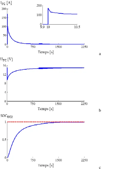
A second simulation is performed by considering the values of the UC presented by [21] and summarized in Table 4. These values represent a UC made of 6 cells connected in series. The number of cells of the PEMFC is imposed to be 18. Figure 4 and Table 5 summarize the results.
Table 4 UC2 (Nominal 583 F) (extracted from [20])
Parameter Equivalent circuit values Parameter Equivalent circuit values
Ci0 / F 422 Ri / mΩ 0.091
Ci1 / mF V-1 28.36 Rd / Ω 2.53
a
b
c
Fig. 4 Charge of UC2. Initial condition UCSOC=0 % - (a) FC current, (b) FC voltage, (c) UC SOC
Table 5 Energy balance for the charge of UC2
Parameter / Initial voltage 0 % Vnom 25 % Vnom 50 % Vnom 75 % Vnom
EFC / W s 1.7230*1e5 1.4879*1e5 1.1376*1e5 6.5056*1e4
ECd / W s 0.0919*1e5 0.0861*1e5 0.0688*1e5 0.3993*1e4
ECeq / W s 1.1084*1e5 1.0687*1e5 0.9101*1e5 5.7223*1e4
ERi / W s 0.4558*1e5 0.2974*1e5 0.1442*1e5 0.3526*1e4
ERd / W s 0.0670*1e5 0.0357*1e5 0.0147*1e5 0.0316*1e4
tload / s 2250 2190 2155 2032
Imax / A 170.6 127.9 85.19 42.5
Ec/EFC 0.6966 0.7761 0.8605 0.9410
Simulation results show that when the sources are interconnected, a transient current of high magnitude flows between the sources. This peak naturally depends on the initial condition of voltage (i.e. the SOC) of the UC. This peak could be much higher than the nominal value of the fuel cell. The effect of high magnitude currents flowing in the fuel cell is studied in next section.
The main branch of the UC stores almost all the energy, and most of the energy is accumulated in the UC at high voltages. Charging the UC from low voltage generates high Joule losses as can be seen in Tables 3
and 5. The losses to charge a completely discharged UC are around 30 % of the energy supplied by the fuel cell; the losses to charge a UC charged at 50 % are around 5-10 % which are more reasonable. It can be concluded that it is not interesting to operate the UC in low voltages because of the high losses. To avoid operation in low voltages, an energy management strategy for the fuel cell has to be considered in order to prevent deep discharges. Moreover, if the UC and FC are connected before starting the latter; the high current peak can nevertheless be reduced if the fuel cell stack is progressively feed with reacting gases, thus leading to a progressive increase of the output voltage, as demonstrated in [5].
As there is no power electronics to control the power flow between the fuel cell and the UC, one solution to protect the UC from surcharges is to limit the number of cells in the FC considering the nominal voltage of the UC. The drawback of this solution is the slow charge to the maximal SOC. This is explained because when the UC are reaching their maximal charge, the difference of potential FCS-UC is very low as well as the current to charge the UC (e.g. the time to charge the first UC in Table 5, from 0 to 50 % is less than 2 minutes, the time to charge it from 50 % to 100 % is more than 30 minutes). A solution to fast recharge is to use more cells in the fuel cell. In this case a protection must be considered such as a Zener diode, however this solution increases the losses in the circuit, the efficiency of this solution is around 90 % as studied by [22-24].
2.2 FC/UC/load
As an example of application of the hybrid source, this section presents simulation results for a passive hybridization of a PEMFC with a bank of UC. The source is used to supply the power to propel a hybrid electric vehicle. The power profile is obtained from collected measures using the ECCE heavy duty vehicle, a fuel cell – ultra capacitor mobile laboratory used to study the implementation and energy management of hybrid sources for hybrid electrical vehicles [18].
The UC are made from 2 modules of 36 cells in series. These two modules are connected in parallel. The equivalent UC nominal value is 90 V – 195 F. The maximal fuel cell power is 14 kW and its nominal current is 155 A. The open circuit voltage is 90 V. The fuel cell has 110 cells and the active surface is 800 cm2. This is selected to avoid surcharging the UC. The power profile was measured on the real operation
of the vehicle [20]. However, in the simulations it is only considered one of the two fuel cell stacks and then the power is reduced as illustrated in Figure 5.
Fig. 5 FC/UC/Load passive hybridization simulation results
The simulation is divided in 3 steps. The first ten seconds, the sources are disconnected and represent the time to start the fuel cell. The UC are initially discharged (SOC=0 %). At t=10 s the UC are connected to the fuel cell and this source starts charging the SOC to the state of charge of 0.85 because of the longtime of charge (see Figure 4). At t=500 s, the vehicle starts and the power profile lasts for 4 minutes. At the end of the period the fuel cell recharges the UC.
Figure 5 and 6a presents the power distribution obtained for the considered power profile with an initial UC SOC of 0 % and 90 % respectively. The current peak (and thus the losses) obtained when the UC and the FC are connected are much higher when the UC SOC is low. Of course, the same analysis can be
done considering the time requested to charge the UC. Figure 6b-d illustrates respectively the power repartition, the UC SOC, the voltage and the current of the fuel cell for an initial UC SOC of 90 %.
a
b
c
d Fig. 6 FC/UC/Load passive hybridization simulation results (zoom) (a) power repartition, (b) UC SOC, (c) FC voltage, (d) FC current, (e) UC current
Additional simulations are performed for the considered power profile when increasing the size of the UC. Figure 7a presents the power repartition considering a 97,5F UC. Figure 7b presents the results considering the 195F UC. Increasing the size of the UC reduces the power supplied by the fuel cell. The peak FCS current is 288 A, 214 A, 177 A, and 153 A for 97.5 F, 195 F, 292.5 F and 390 F UC respectively. With a higher UC, the dynamic FC power supplied is reduced (the UC acts as a filter). The natural drawback is the increase in the quantity of UC (i.e. cost, weight and volume of the system) as well as the time and the peak power to recharge the UC.
3
Fuel Cell Degradation in high current operation
The precedent section shows that when the ultra capacitors are connected to the fuel cell, the current flowing through the fuel cell can reach values much higher than the nominal operation conditions. Short demands of high current densities showed improvements in the performance of the fuel cell due to the elimination of oxygenated species from the platinum surface. At very high current densities, the water produced in the electrochemical reaction is sufficient to maintain adequate humidification conditions in the cells.
As an example, in Horizon fuel cell technologies, a controlled short circuit is applied to reduce the degradation of the fuel cell system; this will regenerate the fuel cell for rated power and keep it conditioned for long performance lifetimes. When the short circuit unit turns on, it can enhance performance of the stack in applications where the stack is turned off for prolonged periods. However, in order to maintain the membrane hydrated on the small FCS, short-circuits are applied during few milliseconds. In the presented study, the short-circuit duration is done for a couple of seconds (3 orders of magnitude higher). Thus, the short-circuit consequences are different and it can be assumed than negative effect is here predominant.
The objective of this section is to study the effect of these high currents versus the fuel cell life span. To reach this aim, an experimental evaluation is considered. A test bench is implemented to short-circuit the fuel cell electrodes and then to impose the fuel cell to supply a maximal current. This permits to study the worst operation conditions in the fuel cell. This condition occurs when a completely discharged UC are connected to the fuel cell.
3.1 Experimental Setup
This section aims to present an experimental study of the operation and degradation in PEMFC stack under electrical short-circuit. A controlled short-circuit is imposed between the electrodes of the fuel cell stack. Then the electrical and fluidic parameters are studied during and after this operation mode. An analysis of the degradation is realized by performing Electrochemical Impedance Spectrometry (EIS).
3.1.1 Fuel Cell Stack and Test Bench
The fuel cell stack is fed with air and hydrogen. It is composed of 40 cells connected in series, with an active surface of 220 cm2 each. The nominal current of the PEMFC is 110 A, the nominal (electrical)
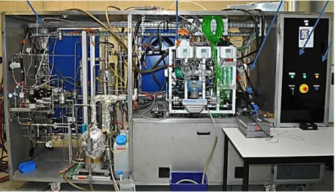
power is 3.8 kW and the nominal operating temperature is 80 °C. Hydrogen and air stoichiometry rates are fixed to 1.5 and 2 respectively. The test bench illustrated in Figure 8 is used to evaluate the fuel cell in both dynamic and static states [25].
3.1.2 Short-Circuit Procedure
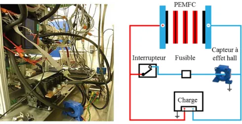
The PEMFC electrodes are directly connected by using a controllable circuit breaker. The current is measured by using a Hall Effect sensor. Fuses are used as redundancy protection (Figure 9).
Fig. 9 Short-Circuit Scheme
3.1.3 Measures
Electrical, thermal and fluidic parameters are measured before, during and after the controlled short-circuit. It allows understanding the physical phenomena occurring in the stack. The EIS is used to determine the dynamic behavior of the fuel cell [26], thus it is used to define reference conditions to quantify the degradation. EIS are performed before and after the short-circuit by using the spectrometer designed by Wasterlain [27].
3.2 Experimental Results
A short-circuit is imposed between the two current outputs of the fuel cell stack. However, the objective is not to perform a destructive test, and then the duration of the short-circuit is limited to avoid strong thermal stress which can degrade permanently the fuel cell. This section presents the experimental results obtained for a short-circuit with a duration of 10 s.
3.2.1 Electrical Behavior
Figures 10a and 10b illustrate the current and voltage during the short-circuit. Figure 10c presents the voltage for each cells of the stack.
Figure 10a shows that the short-circuit current (from 0.5 to 10.5 s) reaches a value of 1100 A (5 A cm-2).
This represents near 10 times its nominal value. However, this current then decreases to stabilize at a value of near 2 times the nominal value. This is a relatively low value compared with electrical machines; here the current is limited by the mass transfer losses and by the hydrogen flow. This confirms the results presented by Hinaje et al. [12] which use this phenomenon to use the fuel cell as a current source controlled on the hydrogen flow. This electrical behavior resembles to the transient presented in Figures 3a and 4a. Figure 10b shows that the stack voltage drops near to 0 V, even some cells present reverse potentials as illustrated in Figure 10c and explained by [17]. This occurs mainly in the cells that are far from the air input. The figure also shows that in some cells the voltage drops only about 50 % of its nominal value, this is mostly the case in the cells located near the air input.
It should be noted that the short-circuit occurs when the fuel cell is working at its nominal operating point (110 A). After short-circuit the fuel cell operates under open circuit voltage mode.
a
b
c Fig. 10 PEMFC electrical behavior during short-circuit
(a) current, (b) stack voltage, (c) individual cell voltage
3.2.2 Thermal and Fluidic Behavior
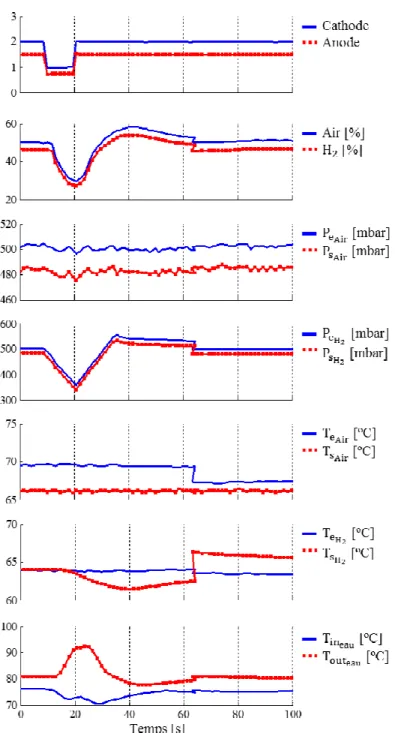
Figure 11 presents the experimental results for the gas stoichiometry, humidity and pressure, air temperature, H2 temperature and water (cooling) temperature. It is important to highlight that the time
scale is not the same than in Figure 10, this is because the fluidic time constants are much higher than the electrical ones; in Figure 11 the short-circuit is occurring from 9 s to 19 s.
During the short-circuit the gas are consumed at a very high rate. The stoichiometric factors air/H2
decrease from 2/1.5 to 1/0.75 respectively. As the supply in gas is proportional to the current supplied to the load, water is produced at a very high rate. The excess of liquid water contributes to the reduction of the membrane resistance while reducing the ohmic losses in the membrane [12, 16].
Here, relative humidity is calculated based on the dew point of the incoming gas and the temperature in the fuel cell. This is an image of the relative humidity of the gas in the fuel cell. The change observed is related to the temperature variation in the fuel cell during the short-circuit.
The high current, even during a short time, causes a rise in the stack temperature; the heat must thus be evacuated. This originates a high thermal gradient, the temperature (measured based on the cooling water temperature) rises to 92 °C; 15 % higher than the nominal value. Local heating resulting from the short-circuit is not compensated by the cooling system. It can be seen in Figure 11 that there is good response
from the stack cooling system during short-circuit, but this action is too slow to counteract the global rise in temperature of the fuel cell during short-circuit. Presumably, if the short-circuit was maintained longer, the local heating could provoke a destruction of the membranes. In our case, the short-circuit was deliberately limited in time to avoid the destruction of the membranes. This was then checked by the impedance spectrum plotted before and after the short-circuit test.
No detailed studies have been reported for the understanding of fuel cell degradation mechanisms in high current operation. Gerard et al. [28] studied the impacts on the local conditions and ageing during oxygen starvation (typically the same type of phenomenon than can be obtained locally during the short-circuit). In fact, lot of experimental and theoretical studies has been made on the case of sub-stoichiometric air/H2
and high local current densities associated (above 2000 mA cm-2 at the input of the stack) when the
stoichiometry tends to 1, evidently in this case the temperature that rises locally are very important. For a water cooling outlet at 92°C, it is almost certain that some area of the FC/membrane reach temperatures of 100°C, particularly these areas associated with the arrival of the reactive gases.
According to [29], an increase in the load current is associated with higher power dissipation within the stack and subsequent temperature elevation. An excessive increase of fuel cell temperature results in thermal degradation, it generally involves changes in the molecular weight (and molecular weight distribution) of the polymer and in physical properties such as ductility decrease, embrittlement and cracking [30-32]. Excessive heat generated locally contributes also to the pinhole formation. The pinhole causes temperature spike and negative current density, and their magnitude will depend on the pinhole size and operating conditions.
The reactant feed gas is proportional to the current supplied and the amount of heat that must be eliminated increases significantly. As mentioned by [16], a very large overcurrent, in a short period of time causes a temperature increase of the FC. A temperature increase with an adequate hydration may lead to an acceleration of the diffusion of the hydrogen protons in the electrolyte membrane, thereby reducing the potential ohmic losses in the membrane. Nevertheless, in [33], the authors suggest that a high current generates an important production of water on the cathode side, the membrane will nevertheless dry out by electro osmotic drag.
During a short circuit, it is difficult to supply the reacting gases to the reaction sites fast enough. Thus, the operating conditions can be identified as relating to the right part of the polarization curve (mass transportation limitation). If high current densities are assumed, the finite mass transport rates limit the supply of reactant and evacuation of products [34]. A concentration gradient therefore occurs, contributing to loss of cell potential.
If a cell cannot produce enough electrons/protons from the H2 fuel to complete the fuel cell reaction, for
the current being drawn, portions of the carbon catalyst support layer react to make up the difference. This is known as carbon corrosion, and is very harmful to the cell. If carbon corrosion occurs, the cell voltage will be driven in a cell inversion. Carbon support corrosion can arise when local fuel starvation occurs; sufficient gas is supplied to the cell but the current distribution is not homogeneous and the fuel supplied is unevenly distributed across the membrane and electrode surfaces [34]. Carbon support degrades faster with increased humidity and temperature, and eventually leads to structural changes [34-36].
3.2.3Electrochemical Impedance Spectroscopy
Electrochemical impedance spectroscopy (EIS) has been widely used to study fuel cell degradation because its ability to distinguish, in the frequency domain, the individual contributions of electrode processes to the total impedance spectra and because EIS provides information on the microscopic scale of the electrochemical system [16, 37]. Figure 12 presents impedance spectra results before and after short-circuit. Tables 6 and 7 summarize the polarization and ohmic resistance of the individual cells (in groups of 4). Experimental results exhibit that the change in the impedance spectra before and after short-circuit is not so pronounced, the value of the internal resistance of the stack increases by about 1.23 % (passing from 17.24 to 17.03 mΩ). Similarly, for low frequencies, the polarization resistance of the stack evolves from 93.77 to 94.42 mΩ, an increase of 0.69%. The value of the internal resistance of the stack cannot be used as an indicator of degradation after short-circuit. Nevertheless, the polarization resistance
slight increases during short-circuit on the low frequency capacitive arc associated with diffusion phenomena.
On the basis of these scale-1 experimental tests, it is clear that the overall effect of rapid short-circuits do not seem to impact the performance of the FCS. Nevertheless, at this time, no report can be found in the literature relating to what happens locally in the electrolyte membrane under these operating conditions. Indeed, local heating could have a medium-term impact on the performances of the FCS or even its ability to be operated.
Fig. 11 PEMFC fluidic behavior during short-circuit - (a) Stoichiometry, (b) Gas humidity, (c,d) Air/H2
a
b
c
Fig. 12 Nyquist plot corresponding to (a,b) cells, (c) stack before and after the short-circuit (nominal conditions)
Table 6 Ohmic resistances (Rm / mΩ). Before and After Short-Circuit (10 s)
Cell n° [5-8] [9-12] [13-16] [17-20] [21-24] [25-28] [29-32] [33-36] [37-40] Stack
Before 1.83 1.76 1.74 1.71 1.70 1.66 1.61 1.57 1.63 17.03
After 1.87 1.80 1.72 1.71 1.72 1.68 1.62 1.58 1.63 17.24
Table 7 Polarization resistances (Rp / mΩ). Before and After Short-Circuit (10 s)
Cell n° [5-8] [9-12] [13-16] [17-20] [21-24] [25-28] [29-32] [33-36] [37-40] Stack
Before 9.99 9.63 8.96 9.41 9.21 8.65 8.31 8.41 8.02 93.77
4
Conclusions
The paper presents a simulation study about the hybridization of UC and FCS without using power electronics. The passive hybridization is studied to recharge the UC and to supply a load. The results demonstrate the interest of this hybridization as well as its drawbacks. As a high magnitude current flows from the fuel cell to recharge the UC, an experimental study of the operation of PEM under electrical short-circuit is realized. After a short-circuit occurs, a high peak of current appears (near 10 times nominal current) but decreases to stabilize in a much lower value (two times the nominal current), this is due to the mass transfer losses limitation and the hydrogen flow as also concluded in [12]. The voltage in the cells varies and depends on the relative position regarding the gas input. The voltage drops in all the cells and even some cells present reversal potentials as presented in [17]. The temperature rises but the dynamic is much slower than the electric ones. It is difficult to conclude the degradation by using EIS because the results before and after the circuit are very similar. This could be because the short-circuits were maintained for a relatively short duration.
In this study, the experimental short-circuits were realized only 4 times. For further research, it could be interesting imposing these conditions multiple times and for longer duration. A solution envisaged to mitigate aging linked to the start-up of the FCS is to connect the UC before starting the fuel cell; as the fuel cell is progressively fed with gas the voltage increases progressively, and the high current peak can thus be reduced. Nevertheless, even in this case, a short-circuit remains possible when considering power electronics fault and the study of their effects could be another interesting perspective of this work.
References
[1] M. Uzunoglu, M. S. Alam, Energy Convers. Manage. 2007, 48, 1544.
[2] O. Erdinc, B. Vural, M. Uzunoglu, Y. Ates, Int. J. Hydrogen Energy 2009, 34, 5223.
[3] J. Junbo, W. Gucheng, C. Yew Thean, W. Youyi, H. Ming, IEEE Trans. Ind. Electron. 2010, 57, 1945.
[4] N. Bizon, paper presented at the International Conference on Applied Electronics (AE) 2012, 21. [5] B. Morin, Ph.D Thesis, Institut National Polytechnique de Toulouse, Toulouse, France, 2013. [6] M. Garcia-Arregui, C. Turpin, S. Astier, paper presented at the International Conference on Clean
Electrical Power (ICCEP '07) 2007, 474.
[7] S. F. Tie, C. W. Tan, Renewable Sustainable Energy Rev. 2013, 20, 82.
[8] P. Rodatz, G. Paganelli, A. Sciarretta, L. Guzzella, Control Engineering Practice 2005, 13, 41. [9] B. Davat, S. Astier, T. Azib, O. Bethoux, D. Candusso, G. Coquery, A. De Bernardinis, F. Druart,
B. Francois, M. Garcia Arregui, F. Harel, D. Hissel, J-P. Martin, M-C. Péra, S. Pierfederici, S. Raël, D. Riu, S. Sailler, Y. Bultel, T. Creuzet, C. Turpin, T. Zhou, 8th International Symposium on
Advanced Electrochemical Motion Systems & Electric Drives Joint 2009, 1.
[10] H. Zhao, A. F. Burke, Fuel Cells 2010, 10, 879.
[11] J. Bernard, M. Hofer, U. Hannesen, A. Toth, A. Tsukada, F. N. Büchi, P. Dietrich, J. Power
Sources 2011, 196, 5867.
[12] M. Hinaje, S. Raël, J. P. Caron, B. Davat, Int. J. Hydrogen Energy 2012, 37, 12481. [13] A. Nishizawa, J. Kallo, O. Garrot, J. Weiss-Ungethüm, J. Power Sources 2013, 222, 294.
[14] M. Hinaje, paper presented at the IEEE Vehicle Power and Propulsion Conference (VPPC), Chicago, USA, 2011, 1.
[15] T. Yalcinoz, M. S. Alam, Int. J. Hydrogen Energy 2008, 33, 1932.
[16] S. Wasterlain, D. Candusso, D. Hissel, F. Harel, P. Bergman, P. Menard, M. Anwar, J. Power
Sources 2010, 195, 984.
[17] M. M. Mench, E. C. Kumbur, T. N. Veziroglu, Polymer Electrolyte Fuel Cell Degradation, Elsevier Science, 2011.
[18] L. Boulon, K. Agbossou, D. Hissel, P. Sicard, A. Bouscayrol, M. C. Péra, Renewable Energy
[19] L. Zubieta, R. Bonert, IEEE Trans. Ind. Appl. 2000, 36, 199.
[20] J. Solano Martínez, Ph.D Thesis, Université de Franche-Comté, Belfort, France, 2012.
[21] J. Solano Martínez, paper accepted at the IEEE Vehicle Power and Propulsion Conference
(VPPC), Beijing, China, 2013.
[22] D. Linzen, S. Buller, E. Karden, R. W. De Doncker, IEEE Trans. Ind. Appl. 2005, 41, 1135. [23] Y. Diab, P. Venet, G. Rojat, Proc. 2nd Eur. Symp. Super Capacitors Appl., Lausanne, Switzerland,
2006.
[24] P. Barrade, S. Pittet, A. Rufer, paper presented at the International Power Electronics Conference
(IPEC 2000), Tokyo, Japan, 2000.
[25] D. Candusso, F. Harel, A. De Bernardinis, X. François, M. C. Péra, D. Hissel, P. Schott, G. Coquery, J. M. Kauffmann, Int. J. Hydrogen Energy 2006, 31, 1019.
[26] T. E. Springer, T. A. Zawodzinski, M. S. Wilson, S. Gottesfeld, J. Electrochem. Soc. 1996, 143, 587.
[27] S. Wasterlain, D. Candusso, F. Harel, D. Hissel, X. François, J. Power Sources 2011, 196, 5325. [28] M. Gerard, J.-P. Poirot-Crouvezier, D. Hissel, M.-C. Pera, Int. J. Hydrogen Energy 2010, 35,
12295.
[29] M. J. Khan, M. T. Iqbal, Fuel Cells 2005, 5, 463.
[30] A. Collier, H. Wang, X. Zi Yuan, J. Zhang, D. P. Wilkinson, Int. J. Hydrogen Energy 2006, 31, 1838.
[31] G. Tian, S. Wasterlain, I. Endichi, D. Candusso, F. Harel, X. François, M. C. Péra, D. Hissel, J. M. Kauffmann, J.Power Sources 2008, 182, 449.
[32] J. Wu, X. Z. Yuan, J. J. Martin, H. Wang, J. Zhang, J. Shen, S. Wu, W. Merida, J. Power Sources
2008, 184, 104.
[33] W. Friede, Ph.D Thesis, Institute National Polytechnique de Lorraine, Lorraine, France 2003. [34] H. Wang, H. Li, X. Yuan, PEM Fuel Cell Durability Handbook, Taylor & Francis Group, 2011. [35] R. Borup, J. Meyers, B. Pivovar, Y. S. Kim, R. Mukundan, N. Garland, D. Myers, M. Wilson, F.
Garzon, D. Wood, P. Zelenay, K. More, K. Stroh, T. Zawodzinski, J. Boncella, J. E. McGrath, M. Inaba, K. Miyatake, M. Hori, K. Ota, Z. Ogumi, S. Miyata, A. Nishikata, Z. Siroma, Y. Uchimoto, K. Yasuda, K. Kimijima, N. Iwashita, Chemical Reviews 2007, 107, 3904.
[36] Y. Yu, H. Li, H. Li, H. Wang, X.-Z. Yuan, G. Wang, M. Pan, J. Power Sources 2012, 205, 10. [37] R. Onanena, L. Oukhellou, D. Candusso, F. Harel, D. Hissel, P. Aknin, Int. J. Hydrogen Energy
![Fig. 1 FC/UC passive hybridization Fig. 2 UC equivalent circuit model [19]](https://thumb-eu.123doks.com/thumbv2/123doknet/7994711.267847/5.892.500.729.162.337/fig-fc-passive-hybridization-fig-equivalent-circuit-model.webp)
![Table 2 UC1 (Nominal 470 F) (extracted from [19]) Parameter Equivalent circuit values C i0 / F 270 C i1 / F V -1 95 C d / F 100 R i / m Ω 2.5 R d / Ω 0.9 V nom / V 2.5](https://thumb-eu.123doks.com/thumbv2/123doknet/7994711.267847/6.892.187.710.827.999/table-nominal-extracted-from-parameter-equivalent-circuit-values.webp)
![Table 4 UC2 (Nominal 583 F) (extracted from [20])](https://thumb-eu.123doks.com/thumbv2/123doknet/7994711.267847/7.892.291.652.132.781/table-uc-nominal-f-extracted.webp)