Thèse de Doctorat
é c o l e d o c t o r a l e s c i e n c e s p o u r l ’ i n g é n i e u r e t m i c r o t e c h n i q u e s
U N I V E R S I T É D E F R A N C H E - C O M T É
n
Contribution to Digital Microrobotics:
Modeling, Design and Fabrication of
Curved Beams, U-shaped Actuators
and Multistable Microrobots
Thèse de Doctorat
é c o l e d o c t o r a l e s c i e n c e s p o u r l ’ i n g é n i e u r e t m i c r o t e c h n i q u e s
U N I V E R S I T É D E F R A N C H E - C O M T É
TH `ESE pr´esent´ee par
H
USSEIN
H
USSEIN
pour obtenir le
Grade de Docteur de
l’Universit´e de Franche-Comt´e
Sp´ecialit´e : Sciences pour l’ing´enieur
Contribution to Digital Microrobotics: Modeling,
Design and Fabrication of Curved Beams, U-shaped
Actuators and Multistable Microrobots
Unit´e de Recherche : FEMTO-ST, UMR CNRS 6174
Soutenue publiquement le 11 D`ecembre 2015 devant le Jury compos´e de : ORPHEE´ CUGAT Pr´esident du jury Directeur de Recherche, CNRS, G2ELAB,
Grenoble
JOEL¨ POUGET Rapporteur Directeur de Recherche, CNRS, ∂’Alembert,
Paris
CHRISTINEPRELLE Rapporteur Professeur, UTC, Compi`egne
RAFICYOUNES Examinateur Professeur, UL, Beyrouth Liban
PHILIPPELUTZ Directeur de th`ese Professeur, UFC, Besanc¸on
YASSINEHADDAB Encadrant de th`ese Professeur,UM, Montpellier
PATRICE LEMOAL Encadrant de th`ese Charg´e de recherche , CNRS, FEMTO-ST,
Besanc¸on
GILLES BOURBON Encadrant de th`ese Ing´enieur de recherche, CNRS, FEMTO-ST,
Acknowledgment
My thesis was realized in the AS2M department of Femto-st institute, and it has been supported by the Labex ACTION project. I would like to express my sincere gratitude to all the members of the department, starting from the director Micha¨el Gauthier and the colleagues for their support and the bright and stimulating environment of the department. I would like also to express my sincere thanks to all the Labex ACTION project members.
I would like to express the deepest appreciation and thanks to my advisors Prof. Philippe Lutz, Prof. Yassine Haddab, Dr. Patrice Le Moal and Dr. Gilles Bourbon, who supported me greatly during the thesis and did every possible effort to help me in order to achieve the best results. I am more than thankful for them for their kindness, patience, and endless encourage-ment. I could not have imagined having a better advisor and mentor for my Ph.D study. Thanks to you.
I would like to thank the rest of my thesis committee: Dr. Orph´ee Cugat, Dr. Jo¨el Pouget, Prof. Christine Prelle, and Prof. Rafic Younes, for serving as my committee members and for letting my defense to be an enjoyable moment. Your insightful comments incented me to widen my research from various perspectives. Thanks to you.
A special thanks to my family, you are everything for me. Words cannot express how grate-ful I am to my mother and father for all of the sacrifices that you have made on my behalf. I would also like to thank my brother and sisters for always being there beside me through thick and thin.
I specially extend appreciation to my beloved wife, Fatima, who was always my support. The day you stepped into my life, you changed it into something so beautiful and meaningful. You are just so amazing to have around. I love you so much.
Finally, a new ray of sunshine will enter our lives in the next days; we are waiting the arrival of our little princess Zahraa. Thank you my babe for the pleasure and happiness you have added before your arrival. We are waiting impatiently ....
Hussein Hussein
Contents
General introduction 1 1 Digital Microrobotics 5 1.1 Introduction . . . 6 1.2 Digital microrobot . . . 8 1.2.1 Digital microrobotics . . . 8 1.2.2 The DiMiBot . . . 101.2.3 Advantages and challenges . . . 13
1.3 Solutions for digital systems . . . 16
1.3.1 Switching function . . . 16
1.3.2 Holding function . . . 18
1.3.3 Multistable mechanisms . . . 26
1.4 Thesis objectives and working axes . . . 30
1.4.1 First axis: Analytical design optimization . . . 31
1.4.2 Second axis: DiMiBot with multistable modules . . . 32
1.5 Conclusion . . . 33
2 Curved beam bistable mechanism 35 2.1 Introduction . . . 37 2.2 Buckling of a beam . . . 38 2.2.1 Buckling model . . . 38 2.2.2 Buckling equation . . . 40 2.2.3 Bifurcation of solutions . . . 42 2.3 Snapping force . . . 45
2.3.1 Without high modes of buckling . . . 45
2.3.2 Considering high modes of buckling . . . 46
2.4 Bistability conditions . . . 49
2.5 Stress State . . . 50
2.5.1 Without high modes of buckling . . . 51
2.5.2 Considering high modes of buckling . . . 53 vii
2.6 FEM simulations and comparison . . . 55
2.7 Design and optimization . . . 57
2.7.1 Influence of the dimensions and properties on the mechanical behavior 58 2.7.2 Curved beam design . . . 63
2.7.3 Limits of the miniaturization . . . 68
2.8 Conclusion . . . 71
3 U-shaped electrothermal actuators 73 3.1 Introduction . . . 75
3.2 Electrothermal model . . . 77
3.2.1 Electrothermal equation . . . 77
3.2.2 Lineshaped beam electrothermal response . . . 77
3.2.3 Actuator electrothermal response . . . 79
3.3 Thermo-mechanical model . . . 85
3.4 Simulations, Experiments and discussion . . . 88
3.4.1 Electrothermal response . . . 89
3.4.2 Mechanical response . . . 92
3.5 Design and optimization . . . 95
3.5.1 Maximal voltage . . . 95
3.5.2 Characteristic curve of the actuator . . . 96
3.5.3 Influence of the parameters on the actuator’s performance . . . 99
3.5.4 Design methodology of the actuator . . . 106
3.6 Conclusion . . . 112
4 Multistable module and DiMiBot 113 4.1 Introduction . . . 115
4.2 Principle of the multistable mechanism . . . 117
4.3 System 1: an accurate bistable mechanism . . . 119
4.3.1 Microfabrication tolerances . . . 120
4.3.2 Accurate positioning mechanism . . . 121
4.3.3 Design of the different components in system 1 . . . 124
4.4 System 2 and the teeth configurations . . . 127
4.4.1 Functioning . . . 127
4.4.2 Teeth configurations . . . 128
4.5 System 3 and the moving part . . . 130
4.6 Multistable module global design . . . 132
4.7 Multistable modules in the DiMiBot . . . 133
4.8 Conclusion . . . 137
5 Fabrication and experiments 139 5.1 Introduction . . . 141
5.2 Fabrication process . . . 141
5.2.1 General process flow . . . 141
CONTENTS ix
5.3 Technological aspects in the fabrication process . . . 148
5.3.1 Hard mask (Photomask A) . . . 148
5.3.2 Gold patterns (Photomask B) . . . 149
5.3.3 Device layer etching (Photomask C) . . . 151
5.3.4 Substrate etching . . . 154
5.3.5 HF release . . . 154
5.4 Force measurement experiments . . . 157
5.4.1 Rectilinear beams . . . 159
5.4.2 Curved beams . . . 159
5.5 Experiments on the actuators . . . 161
5.5.1 Experimental setup . . . 161
5.5.2 Remarks noticed in the experiments . . . 163
5.6 Multistable module experiment . . . 165
5.6.1 Activation of the multistable modules . . . 166
5.6.2 Wire bonding . . . 166
5.6.3 Electronic circuit . . . 166
5.6.4 Tests on the different systems of the multistable module . . . 169
5.6.5 Sequence orders to make steps . . . 169
5.6.6 Experimental functioning . . . 169
5.7 Conclusion . . . 173
Conclusion and perspectives 175 Conclusion . . . 175
Perspectives . . . 177
Actuators . . . 177
Multistable module . . . 178
Towards a planar multistable microrobot with holding forces . . . 178
Towards a 3D multistable microrobot in three dimensions . . . 180
List of Figures
1.1 Assembly platform for a microspectrometer (a), the assembled
microspectrom-eter (b) [28]. . . 6
1.2 Schematic diagram for the functioning of a positioning system with feedback. . 7
1.3 Unstable, discrete, stable and maintained positions. . . 8
1.4 Example of the ball on a surface in different positions. . . 9
1.5 Schematic diagram for the functioning of a digital microrobot. . . 10
1.6 Schematic of the general structural architecture of the DiMiBot. [12]. . . 11
1.7 Drawing of the DiMiBot with four bistable modules with zooms on a bistable module, a compliant hinge and the end effector.. . . 12
1.8 Workspace of the fabricated prototype of the DiMiBot. . . 15
1.9 Holding principle via passive locking actuator(a), optical switch using passive locking actuator [26] (b). . . 20
1.10 Holding principle via permanent magnet. . . 20
1.11 Top (a) and front view (b) of a quadristable system [104]. . . 21
1.12 Precompressed curved beam actuated using two SMA actuators [136] (a), pre-stressed beam nanowire as micromechanical memory [15] (b). . . 22
1.13 2x2 MEMS optical switch using preshaped curved beams [79] (a), comb drive bistable actuator using hinged preshaped curved beams [72] (b). . . 22
1.14 The example of the ball on a surface in analogy with the buckled beam structure principle. The driving force curve is shown in the bottom with respect to the ball position. . . 23
1.15 The example of the ball on a surface with stop blocks. . . 24
1.16 Configurations of the stop blocs of the bistable module, in the DiMiBot, in three different states: as-fabricated, at position 1 and at position 2. . . 25
1.17 Functioning principle of an electrostatic inchworm actuator [35]. LA1 and LA2 latch the two shuttles (step 0), LA1 unlatch the first shuttle (step 1), DA is activated which moves the first shuttle ahead (step 2), LA1 latch the first shut-tle (step3), LA2 unlatch the second shutshut-tle (step 4), finally, DA is disactivated which moves the second shuttle ahead. . . 28
1.18 Functioning principle of stick-slip actuators (a), drawing of stick-slip device
working around and along a tube [108] (b). . . 28
1.19 Principle of friction-inertia actuators (a), a friction-inertia microrobot [94] (b). 29 1.20 Principle of ultrasonic actuators [65] (a), XY drive which uses ultrasonic prin-ciple [30] (b). . . 29
1.21 Architecture of the DiMiBot with multistable modules. . . 32
1.22 Woking axes and the following chapters of the thesis. . . 34
2.1 Buckling of a beam before and after a critical axial compression. . . 38
2.2 Transition between the two stable positions of a buckled beam as a result of a lateral force applied in the middle of the beam. . . 38
2.3 Clamped-clamped curved bistable beam at the initial position and after deflec-tion. . . 39
2.4 A beam in bending (a), bending stress distribution along the thickness and bend-ing moment in a section (b) forces and moments equilibrium in a section of a buckled beam(c). . . 40
2.5 The first three buckling shape modes . . . 42
2.6 Transition between the two stable positions of two curved beams connected in the middle, mode 3 appears during transition. . . 44
2.7 Snapping force solutions without considering high modes of buckling for Q <p(16/3), Q = p(16/3) and Q > p(16/3) respectively. . . 46
2.8 Evolution of the normalized axial stress N in the first kind of solution in function of Q ratio. N is constant in the second and third kinds of solution. The shape of the curved beam in the first, second and third case. . . 48
2.9 Evolution of the normalized applied force F for the curved beam for different Q values when mode 2 is constrained. . . 48
2.10 Evolution of the maximal stress in the beam during deflection depending on Q. 52 2.11 Evolution of the maximal total stress during deflection for Q = 2, Q = 2.4 and Q=3. . . 55
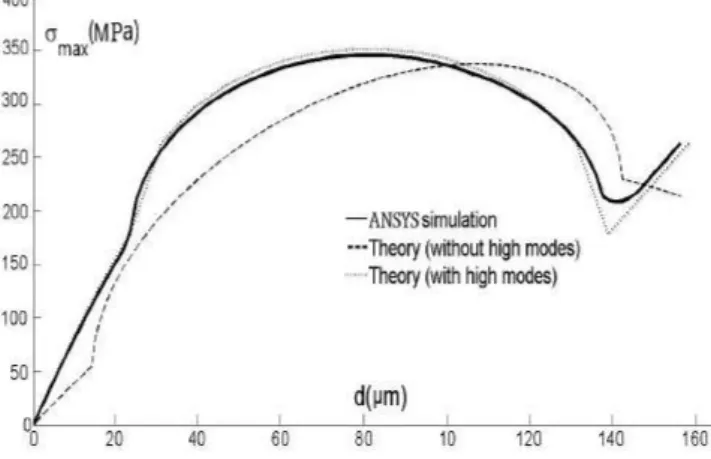
2.12 Comparison of the snapping-force behavior during deflection between theory and FEM simulation. . . 55
2.13 Comparison between the maximal stress value during deflection between theory ans FEM simulation. . . 56
2.14 Comparison between the bending maximal stress value during deflection with and without high modes of buckling. . . 57
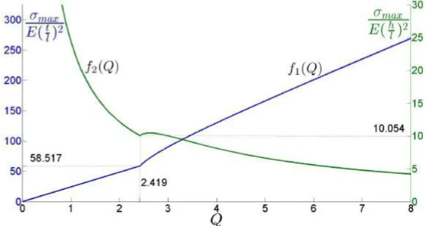
2.15 Evolution of the maximal stress in function of the critical ratio Q according to f1(Q)(blue curve left axis) and to f2(Q)(green curve right axis). . . 59
2.16 Evolution of the condition on K1t/lwith respect to Q. . . 60
2.17 Evolution of the condition on K1h/lwith respect to Q. . . 60
2.18 Evolution of the top of the snapping forces ftop with respect to Q according to f3(Q)(blue curve left axis) and to f4(Q)(green curve right axis). . . 62
2.19 Evolution of the distance between the two stable positions with respect to Q. . 62
2.20 Evolution of ftopin front of the bistable distance ∆stab. . . 63
LIST OF FIGURES xiii 2.22 Important snapping points for the design of curved beams in the bistable
mod-ule. . . 65
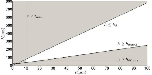
2.23 Field of possibilities for the value of the thickness and the height that is con-cluded from the conditions extracted from the specifications and limitations. The possible dimensions are in the white part. . . 68
3.1 U-shaped electrothermal micoractuator. . . 75
3.2 Schema of lineshaped microbeam. . . 78
3.3 Unfolded actuator . . . 80
3.4 Distribution of the surface forces N and bending moments Mb in the actuator when it is anchored at the flexure end and free in the other side after applying virtual unit forces and moment at the free border of the hot arm, (a), (b) and (c), and at the tip of the actuator (d). . . 86
3.5 Dimensions for the U-shaped actuator in the modeling, simulations and experi-ments. . . 89
3.6 Evolution of the temperature distribution in the actuator obtained from the ana-lytical solution after applying 15V voltage at the anchors. . . 90
3.7 Temperature profiles in the actuator obtained analytically at 0, 2, 10, 20, 40, 70, 150, 250, 500 and 1000ms after applying 15V . . . 90
3.8 Evolution of the average temperature with time in the three arms of the actuator after applying 15V voltage. . . 91
3.9 Comparison between the analytical model and ANSYS for the evolution of the average temperature in the hot arm. . . 91
3.10 Layers of the microfabricated actuator. . . 92
3.11 Shape of the actuator at the rest position (a) and during displacement (b) in the videos. . . 92
3.12 Comparison between the analytical model, ANSYS and experiments for the dis-placement curves at the tip of the actuator. . . 93
3.13 Thermal expansion of the hot, cold and flexure arms, cold side and expansion difference between both sides of the actuator after applying a voltage of 15V . . 94
3.14 Evolution of the characteristic curves of the actuator at several instants after applying a constant voltage. . . 99
3.15 The characteristic curve of the actuator at the steady state including the blocking force and free displacement expressions. . . 100
3.16 Influence of changing the general dimensions on the characteristic curve of the actuator: including the general length l (a), the depth b (b), the general width w (c) and l and w simultaneously with the same ratio of changing (d). . . 101
3.17 Evolution of K0 1K30 with respect to c and a for a constant ratio f = 1. . . 102
3.18 Evolution of K0 1K30 with respect to c and f for a constant ratio a = 0.1. . . 103
3.19 Evolution of K0 1K30 with respect to a and f for a constant ratio c = 10. . . 103
3.20 Values of the ratios f and a maximizing the free displacement df reefor different values of c ratio. . . 104
3.21 Evolution of K0 1K30 at the max-free dimensions for different values of c and with respect to a. . . 104
3.22 Evolution of K0
1K30/K20 with respect to c and a for a constant ratio f = 1. . . 105
3.23 Evolution of K0
1K30/K20 with respect to c and f for a constant ratio a = 0.1. . . . 105
3.24 Evolution of K0
1K30/K20 with respect to a and f for a constant ratio c = 10. . . . 106
3.25 Characteristic curves of the actuator before and after t = td. The loaded
dis-placement after t = td must be more important than the desired displacement
dd. . . 107
3.26 The maximal performance that can be reached in terms of the displacement. When the output is considered at the steady state, the voltage that can be applied is lower and the performance is less important. When the output is considered at the peak of the overshoot, the maximal allowable voltage is higher due to the lower temperature and the performance is more important. . . 108 3.27 Evolution of (dss− dd) with respect to the length l. . . 109
3.28 Evolution of dssmax (left column) and lmax (right column) with respect to a.
These values are calculated for c = 20. . . 111 3.29 Evolution of the desired length ldwith respect to c allowing obtaining a desired
displacement dd=80µm. . . 112
4.1 Drawing of the new generation of the DiMiBot. . . 115 4.2 A drawing of the different systems and components in the multistable module.. 116 4.3 Schema of the rest configuration of the multistable mechanism including the
latches and the moving part. . . 117 4.4 Sequence order to make an upward step. Firstly, S2 latch move upwards with
holding the moving part (a), S3latch holds the moving part (b), S2latch releases
the moving part (c), moves downwards (d) and holds the moving part in a bottom position (e), finally, S3latch releases the moving part (f). . . 118
4.5 Sequence order to make a downward step. Firstly, S3 latch holds the moving
part (a), S2latch releases the moving part (b), moves upwards (c) and closes in
the upper position (d), S3latch releases then the moving part (e), finally, S2latch
moves downwards with holding the moving part (f). . . 118 4.6 Drawing of system 1 and its different components. . . 119 4.7 Usual etching process steps. Photoresist deposition and UV light exposure using
a photomask (1), photoresist developing (2), DRIE of the silicon layer (3). . . 120 4.8 Distances between the sidewalls of two parallel patterns in the design (a) and
after fabrication (b). . . 121 4.9 Drawing of the accurate positioning mechanism in the design, the important
dis-tances between the different components are shown with considering the fab-rication tolerances (a). Drawing of the accurate positioning mechanism after activation where the movable parts are suspended to their locks and the moving part is in the initial position (b). . . 122 4.10 Configuration of the mechanism to compensate the fabrication tolerances. The
mechanism to realize the initial activation distance d as fabricated (a) and after the initial activation (b). The mechanism to define the step size s as fabricated (c) and after the initial activation (d). . . 124
LIST OF FIGURES xv 4.11 Evolution of the snapping force of preshaped curved beams during deflection
for Q < 2.31 and Q > 2.31. . . 125 4.12 Snapping force evolution of the curved beams in system 1 during deflection. . . 126 4.13 Important distances and elastic forces in the as-fabricated configuration of
sys-tem 1 (a), after activation (b) and after switching to the second position (c). . . 126 4.14 Drawing of system 2 including S2latch and two electrothermal actuators, and a
zoom on the teeth of the latch and the moving part before and after activation. . 127 4.15 Evolution of the retracting force after deflection of the gantry in each side of the
latch in system 2. . . 128 4.16 Zoom on the contact zone between the moving part and S2 latch in the
as-fabricated configuration (a), when the latch holds the moving part (b) and when it releases the moving part (c). . . 128 4.17 Two possible configurations of the teeth dimensions allowing engaging the teeth
at each step. Small (a) and wide (b) teeth configurations. The teeth dimensions are shown at the left while the engagement shape of the teeth between two con-secutive positions of the moving part is shown at the right. . . 129 4.18 Drawing of system 3 including S3latch, two electrothermal actuator, and a zoom
on the teeth between the latch and moving part. . . 130 4.19 Evolution of the retracting force after deflection of the gantry of the latch in
system 3. . . 130 4.20 Moving part of the multistable module connected to curved beams. . . 131 4.21 Evolution of the snapping forces of the curved beams connected to the moving
part after deflection and their values at each stable position. . . 131 4.22 Drawing of the multistable module including the support, conductive lines and
the different systems. . . 133 4.23 Drawing of the multistable DiMiBot including the multistable modules, the
sup-port, the conductive lines, and the top head mechanism relating the moving parts to the end effector. . . 134 4.24 Drawing of the head mechanism at the head of the DiMiBot including the end
effector, the beams and the compliant hinges. . . 134 4.25 Workspace of the DiMiBot which consists of 169 discrete positions. . . 135 4.26 Evolution of the retracting force in the bottom left hinge when the left and right
modules are in the different stable positions. . . 136 5.1 Fabrication process steps in the thesis of Vincent Chalvet [12]. Aluminum layer
deposition and patterning (1), device and handle layers etching using DRIE pro-cess (2-3), structure releasing from the wafer using RIE of the buried oxide (4). 142 5.2 Fabrication process steps. SiO2 hard mask etching on the backside (1), gold
layer deposition (2), device and handle layers etched using DRIE process (3-4), structure releasing from the wafer using HF wet etching (5). . . 143 5.3 Example of the layout in the cell of a multistable module. . . 144
5.4 States of a multistable prototype in the wafer during the fabrication process. top view at the initial state (a), after deposition of the gold patterns (b), after etching the device layer (c), after releasing the useless parts (d), after releasing
the prototype from the wafer, top view (e) bottom view (f). . . 145
5.5 Layout of the DiMiBot with multistable modules. . . 146
5.6 Layout of an accurate bistable module (system 1). . . 146
5.7 Layout of the actuator prototypes with and without loads. . . 147
5.8 Layout of preshaped curved beams test. . . 147
5.9 Layout of a prototype for measuring the stiffness of rectilinear beams. . . 148
5.10 Process steps for patterning the hard mask in the backside. . . 149
5.11 Process steps for sputtering and patterning the gold patterns. . . 150
5.12 Gold patterns after sputtering and patterning. . . 151
5.13 Process steps for etching the device layer. . . 152
5.14 SEM photos of the device layer in different places. . . 153
5.15 Microscopic photos of the device layer after etching. Barred dimensions are the layout dimensions, while the others are the real dimensions after fabrication . . 153
5.16 Zoom on the releasing distance in the wafer before HF releasing (a), HF com-patible wafer holder (b). . . 155
5.17 The gold patterns started to peel off from the wafer after inserting it in the HF solution. . . 155
5.18 Wafer from the second run of fabrication where all the structures are released without peeling off the gold patterns. . . 156
5.19 Prototype of the DiMiBot obtained in the second run of fabrication. . . 156
5.20 Schematic diagram of the elements used in the force measurement experiments. 157 5.21 Calibration of the robotic stage signals (actuator and sensor) using an interfer-ometer. . . 158
5.22 Photo of the experience using force sensor. . . 158
5.23 Curved and rectilinear beam prototypes (a), screens showing a direct image from the side and top of the prototypes and force sensor probe (b). . . 159
5.24 force curves of a rectilinear beam obtained in the experiment and FEM sim-ulations. The beam dimensions are as follows: t = 30µm, l = 2040µm, and b=100µm. . . 160
5.25 Snapping force curves of a hinged preshaped curved beams prototype obtained in the experiment and FEM simulations. The beam dimensions are as follows: t=20µm, l = 6.8mm, b = 100µm, thinges=15µm, lhinges=500µm. . . 160
5.26 Micromanipulation station used in the experiments. . . 162
5.27 An actuator in the initial position (a) and after supplying (b). . . 162
5.28 Example of the displacement curves of two actuators with the same characteris-tics, one is free and the other acts on an elastic beam as a load. . . 163
5.29 Evolution of the electrical current after applying a voltage step of 10V in one long step (upper curve) and in successive steps with small delay between each step (lower curve). . . 164
LIST OF FIGURES xvii 5.30 Failure of the actuators during the experiments at the link between the hot and
cold arms for the actuators of the first run (a), and at the flexure for those of the
second run of fabrication. . . 165
5.31 Activation steps of the multistable module under a microscope using three probe needles. . . 167
5.32 A multistable module prototype glued and wire bonded on a PCB . . . 167
5.33 The electronic circuit for supplying the multistable module prototype. . . 168
5.34 Schematic of the relay circuit. . . 168
5.35 Tests on systems 1, 2 and 3 respectively. Three photos are presented for each system, one in the off state, one in the on state and the third one is a zoom on the part that moves. System 1 ((a), (b) & (c)), system 2 ((d), (e) & (f)), system 3 ((g), (h) & (i)). . . 170
5.36 Sequence order for supplying the actuators of each system in the multistable module in order to make upward and downward steps ((a) and (b) respectively). 171 5.37 Functioning of a multistable module during a downward step. The moving part is initially in an upper position (a), S3latch is firstly closed (b), S2latch is then opened (c), and then moved up ((d) & (e)), after that, S2 latch closes (f), S3 latch opens (g) and finally, S2latch moves down with the moving part (h), lower position of the moving part is shown in (i). . . 172
5.38 S3latch remains closed after dis-activating system 3 in the modules with wide teeth configuration (a), the teeth with the small configuration of S2 latch are broken during the experiments (b). . . 173
1 Comparison of the size and workspace between the old and the new generation of the DiMiBot. The two workspaces are at the same scale. . . 176
List of Tables
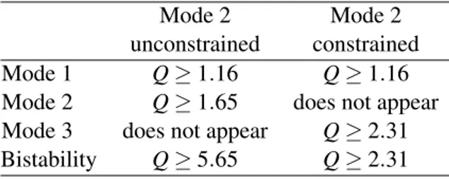
1.1 Classification of holding principles. . . 18 2.1 Conditions on Q in order to reach mode 1, mode 2, mode 3 and the bistability
feature for the preshaped curved beam. . . 50 2.2 Influence of the material properties and the curved beam dimensions on the top
of the snapping force ftop, the strength criterion S, the maximal stress σmaxand
the stroke of deflection dstab. . . 63
2.3 Evolution of tmax, hmax, dtop, dbot, dstab, dsmax, fbot, and ftopat the strength limits
for constant values of l = 1mm, b = 100µm, E = 169GPa and σcrit=0.5GPa.
The values in the table can be recalculated directly for other constant dimensions and materials by multiplying them by the amount mentioned below the columns. 70 3.1 Influence of the different parameters and dimensions of the actuator on its
per-formance at the steady state. . . 106 4.1 Holding forces on the moving part in the upward and downward directions at
each stable position. . . 132 4.2 Minimal holding forces of the stable positions of the multistable module in the
DiMiBot. . . 136
General introduction
Since the mid-20th century, the relationship between humans and machines are experiencing a tremendous development. Electronic products and smart devices have become an extremely important part of our daily life. The actual and coming tech boom makes and will make our life so mush easier. Personal computers, smart phones, cameras, televisions and thousands of other intelligent devices, all are operated by the silicon chips and integrated circuits inside. All the developments nowadays in every single domain of our life including the economy, all kinds of industries, energy production, transport, communication, medicine and many others have been made possible mostly with the help of these powerful silicon chips. They allowed us to access the nearby planets and explore the most distant galaxies in the large scale, and to discover the smaller organisms ever and dive in the particles and atoms world in the downscale.
As we go down in size, there are a number of interesting opportunities coming up, plenty of room, applications and possibilities at the bottom are not yet discovered, while the technol-ogy of small devices is expanding fast. Micro-Electro-Mechanical Systems, or MEMS, is the technology of miniaturized systems. It consists of micro-electro-mechanical elements that are made using the techniques of microfabrication. An extremely large number of MEMS devices are available in the market and many of them have demonstrated performances exceeding those of their macroscale counterparts.
The accelerated research and development in the field of miniature systems and integrated circuits introduced innovative products in our society and revealed the necessity to develop mi-cromanipulators to handle microobjects, fabricate structures, assemble products, interact with a patient, etc.. Two main elements are generally implemented in the design of a micromanipulator: • A tool to make the final function. The tool can be a probe or a microgripper used for handling an object, grasping, performing pick and place, pushing, pulling, positioning, orienting, etc..
• A micropositioning system to position the tool or another substrate. This system must be able to deliver displacement strokes with sub micrometer level accuracy, high precision and repeatability.
Each of these elements has its own characteristics and constraints. As for the tool, scale effect appears due to the miniaturization which is represented by the predominance of surface
forces (adhesion forces ...) on the volume forces (gravity, weight ...) for small objects. Thus, handling an object is more complicated due to the predominance of some forces (such as elec-trostatic, Van der Waals, and capillary forces) which are negligible in traditional manipulation.
As for the micropositioning systems, several issues can be noted such as the limitation in the fabrication process that constraints several aspects in the design (monolithic structure, multi DoF, out of plane displacement, assembly, etc.), the need to make high precision and repeatable systems, the need of sensors for precise positioning, the miniaturization, extending the range of motion in the workspace, the integration in complicated environments, etc.. There are still few work on the design of robotic carriers which are dedicated to the microworld.
Digital microrobotics is an emergent branch in micropositioning systems which avoids the necessity of a feedback to control the position by placing the moving part in several stable posi-tions defined in the design. This avoids the use of bulky sensors which increases the size of the whole device, allows going further in miniaturization, simplifying the control and integrating the device in more complicated environments. Digital microrobots consist generally of multistable mechanisms with switching and holding functions.
For many years, the AS2M department of FEMTO-ST institute focuses in its research on the design of robotic systems suitable for micromanipulation and micro-assembly. In this context, digital microrobotics was recently a matter of concern in the laboratory and it was the topic of two PhD theses made in prior years. Mr. Qiao Chen in his thesis (2010) has proposed a bistable module that is based on the use of a buckled beam structure and U-shaped actuators. Mr. Vincent Chalvet in a subsequent thesis (2013) has proposed a multistable microfabricated digital microrobot DiMiBot, where a number of the bistable modules (those developed in the thesis of Mr. Qiao Chen) are connected with an elastic structure to one end effector. The structure of the DiMiBot allows its end effector to reach a number of discrete positions in a square workspace distribution. The positions are non redundant with respect to the states of the modules, and adding more positions in the workspace is made by adding extra bistable modules. The works made in the actual thesis is a continuation of the previous works made in the department on digital microrobotics. Based on past achievements, the thesis objectives focus on improving the functioning of the DiMiBot, optimizing its design and improving its fabrica-tion process, in order to make it more accurate, more controllable and smaller. To achieve these goals, analytical studies were run for the main components in the DiMiBot (Buckled beam struc-ture and U-shaped actuator) in order to explore their limits in terms of the miniaturization whilst delivering the required performance. In addition, new structure of the DiMiBot was proposed with multistable mechanisms that allow more positions in the workspace without adding more elementary modules and increasing the size. This allows also to realize complex trajectories in the workspace in an open loop control. These two limitations were the main drawbacks of the previous DiMiBot. In addition, some changes were made in the fabrication process in order to reduce the possibility of defects and getting proper structures. A new mechanism was proposed and used in the new DiMiBot in order to compensate the fabrication tolerances and to improve the accuracy of the discrete positions.
Challenges for a new generation of the DiMiBot are presented in Chapter 1. The differ-ent solutions found in literature to realize a digital system in terms of the switching, holding and multistable mechanisms are then presented. The thesis objectives and working axes are presented and the next chapters are introduced. Two working axes were followed in the
the-General introduction 3 sis: the first one concerns the analytical modeling and design of preshaped curved beam and U-shaped actuator, which are the main components in the DiMiBot, the second axis concerns the development and fabrication of a new generation of the DiMiBot with multistable modules. Chapter 2 concerns the modeling and design of a preshaped curved beam. Analytical mod-eling of the snapping forces and internal stresses are firstly investigated. The influence of the material and dimensions on the behavior of the curved beam and its design and optimization are investigated subsequently.
Chapter 3 concerns the modeling and design of the actuator. The problem is treated by a sequence of two analytical models: electro-thermal and thermo-mechanical models. The influ-ence of the different dimensions and electro-thermo-mechanical properties on the behavior of the actuator and its design are investigated in a second stage.
The principle and design of a new generation of the DiMiBot is investigated in Chapter 4. Only two multistable modules are used in the new DiMiBot instead of all the bistable modules in the old generation. The design of the different components, each internal system in the multistable module and the global structure of the module and the DiMiBot are presented.
Finally, the fabrication and experiments are presented in Chapter 5. All the difficulties encountered and solutions provided in the fabrication and the experiments are detailed. Oper-ational prototypes of the multistable module are fabricated and showed a proper functioning in the experiments.
Chapter
1
Digital Microrobotics
Digital microrobotics and the digital microrobot ”DiMIBot” are presented in this chapter including challenges for a new generation of the DiMiBot. A classification of the solutions found in literature that allow realizing digital systems and imporov-ing the DiMiBot is then presented. Finally, the thesis objectives and workimporov-ing axes are presented and the next chapters are introduced.
Chapter contents
1.1 Introduction . . . 6 1.2 Digital microrobot . . . 8 1.2.1 Digital microrobotics . . . 8 1.2.2 The DiMiBot . . . 10 1.2.3 Advantages and challenges . . . 13 1.3 Solutions for digital systems . . . 16 1.3.1 Switching function . . . 16 1.3.2 Holding function . . . 18 1.3.3 Multistable mechanisms . . . 26 1.4 Thesis objectives and working axes . . . 30 1.4.1 First axis: Analytical design optimization . . . 31 1.4.2 Second axis: DiMiBot with multistable modules . . . 32 1.5 Conclusion . . . 33
1.1
Introduction
Numerous are the technological devices in the market where the miniaturization is an objective. This applies in many application areas, from the general public to the highly specialized prod-ucts. The miniaturization of many products becomes more and more a pressing need and the development in this regard is on the rise. The development in microsystems is based mainly on adding extra functionalities in smaller space and on the development of microfabrication techniques.
Having already proven their utility at the macroscale, robots also show their usefulness when we approach the infinitely small. The way to the microworld is not that simple, designing microrobots is not an easy task. MEMS devices and processes are non-standard, they are gen-erally multidisciplinary and multiphysics. The materials and fabrication process are intricately involved. Every product requires a different design, fabrication process, expertise and specific knowledge in various domains simultaneously. Actually, it is not sufficient to miniaturize each part of an existing robot, then assemble them to get a robot that is less than one or few millime-ters in size. For example, engines of the macroscale are not suited to this scale, therefore other MEMS-compatible actuation technologies are employed.
Taking the example of a microspectrometer which is an instrument to measure the wave-length of light [28]. Such an instrument is generally bulky, expensive and cannot be easily ported outside of lab environments, while MEMS technology offers an excellent opportunity for miniaturizing the spectrometer. An automated assembly of the microspectrometer compo-nents is presented in [28] and shown in Figure 1.1.
FIGURE1.1: Assembly platform for a microspectrometer (a), the assembled microspectrometer (b) [28].
Several miniaturized components (glass lenses, optical fibers, laser sources, and detectors onto silicon fixtures and microactuators) are integrated in a single precision bench to form the microspectrometer. Three micropositioning robots are used to move precisely the spectrometer, a MEMS Jammer and a vacuum needle respectively. Three microscopes are used for controlling the assembly process.
1.1 Introduction 7 The race for miniaturization has revealed the need to handle precisely some micrometer-sized objects. To address this need, considerable advances in the microrobotic field are made for generating displacement and manipulating objects at the microscale. Micromanipulators were developed and used in many fields of microrobotics in order to handle an object, fabricate a structure, assemble a product, operate with a patient, etc.. However the necessity of vision and measurement systems to manipulate or assemble micro components remains a challenge to overcome.
Mechanical positioning systems are back-bone systems behind every object manipulation task. Numerous systems for the positioning with high precision at micrometric scale have been developed and are available in the market.
The micropositioning systems work generally in closed loop control and consist of single or multiple actuators, feedback sensors, mechanical platform, control unit and a power source [65]. Figure 1.2 shows a general schematic diagram of the functioning of a positioning system with feedback.
FIGURE1.2: Schematic diagram for the functioning of a positioning system with feedback.
The different components of the continuous positioning system perform their respective functions to achieve positioning tasks in a well defined workspace. Actuators are the compo-nents used to change the state of the system. The input energy is converted through the actuator into motion, force or combination of both. In general, the actuators are able theoretically to reach any position continuously in the workspace. However, continuous energy must be applied to maintain any position.
The main technologies used in MEMS for the actuation are based mainly on thermal, trostatic, magnetic and smart material (piezoelectric material, shape memory alloy (SMA), elec-troactive polymers (EAP), etc.) principles.
Sensors are the components that measure a physical quantity (output variable of the sys-tem) and convert it into a feedback signal to be treated by the control unit. A large number of microsensors have been proposed by MEMS developers for almost every possible sensing modality including temperature, displacement, pressure, inertial forces, chemical species, mag-netic fields, radiation, etc..
Micropositioning systems require measurement and vision systems, often bulky and expen-sive, in order to perform accurate measurement of the position and orientation of the micro-objects. However, most of these sensors provide limited information feedback (for example interferometers measure the displacement only in one direction), forcing to use in a large num-ber. Therefore, the need of one or several sensors is not compatible with the miniaturization of the positionners and their integration in confined spaces. Besides, various problems are
associ-ated with the use of sensors, such as nonlinearity, complex control law, continuous feeding and servoing, complex connectivity, low signal to noise ratio, etc.. These problems vary with respect to the type, technology, material and other properties of the sensor.
In addition to the high precision requirement, the integration of micromanipulation plat-forms in reduced environments (such as scanning and transmission electron microscope) is a recurring problem due to the complexity of the micropositioning systems.
It is often difficult to integrate the various components (sensors, power source, actuators, etc.) into the micromanipulation platform, especially in confined spaces where the integration of these components can be quite challenging. In the efforts to address this challenge, digital concept in micropositioning is introduced couple of years ago [13, 21, 103, 104, 136].
1.2
Digital microrobot
In the previous theses of Vincent Chalvet [12] and Qiao Chen [20], the works have led to the development of a digital microrobot called ”DiMiBot”. Prototypes of the DiMiBot were fab-ricated, characterized and showed a good functioning in the experiments. However, this thesis deals with and provides solutions for some challenging issues of concern for the DiMiBot. The principle of digital microbotics and the DiMiBot are presented in this section. The challenges and requirements for a new generation of the DiMiBot are then presented.
1.2.1 Digital microrobotics
Digital microrobotics is an emergent branch in micropositioning systems which consists in plac-ing accurately the movplac-ing-part/end-effector of the system discretely without feedback. The dig-ital concept avoids the use of sensors and measurement systems by adding a holding function of the mobile part at several positions. Digital microrobots have a defined number of repeatable states called ”discrete positions”, while the positions in between are considered as unstable po-sitions. Based on this definition, the positions of a mobile part can be classified with respect to their level of stability as illustrated in Figure 1.3.
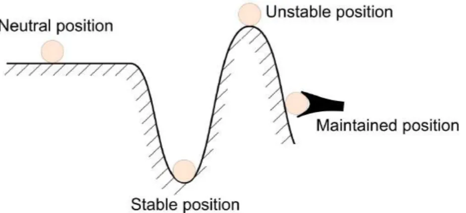
1.2 Digital microrobot 9 The discrete position is a position in a state of equilibrium that does not change with time. The stable position is a discrete position which tends to return to its initial state after a small variation. These positions have a local minimum energy. The maintained position is a stable position that retains its state in front of external disturbance, a force barrier (holding force) must be exceeded before changing the state of the system. In contrast, the unstable position is a position out of static equilibrium or tends to change its state after a very small variation (local maximum energy). The different positions with respect to their stability level are presented in Figure 1.4 using the example of the ball on a surface, only subject to gravity.
FIGURE1.4: Example of the ball on a surface in different positions.
The different positions of the ball represent the possible states of a position. Relatively to the potential energy, the stable position is in a local minimum, while the unstable position in the figure is in a local maximum. The maintained position is maintained using an external tool. The neutral position is a discrete but not stable position. It keeps its new state after displacement.
Under these definitions, the mobile part of digital systems/microrobots passes through un-stable positions during transition between a discrete position and the other. The mechanical structure in these systems is generally a multistable mechanism. The transition between the different stable states of the mechanism is satisfied by two main functions: switching and hold-ing. Generally, the switching function is satisfied using continuous actuators that generate the required force and displacement in the digital system.
The holding function allows maintaining the discrete positions in front of external loads and disturbances. The holding can be ensured either by active or passive maintain. In active maintain, the mechanism needs some external energy to keep its place, while it’s not the case in passive maintain where the mechanism is inherently stable at each position without consuming energy.
Figure 1.5 shows a general schematic diagram for the functioning of digital microrobots. The input on the actuator serves for switching the mobile part of the multistable mechanism between a discrete position and the other. Once the mobile part is placed in the desired position, different holding methods are used in digital systems for the holding.
The digital concept has many advantages, it allows robust and repeatable positions without measurement systems, simplifying the structure, the connectivity and the control, integrating the microrobot in complicated environments, going further in miniaturization and avoiding the
FIGURE1.5: Schematic diagram for the functioning of a digital microrobot.
general problems of sensors in microstructures (size, connectivity, noise accuracy, control laws, etc.). The different solutions used in literature to realize the switching function, the holding function and the multistable mechanisms are presented later in this chapter.
Numerous applications are based on the digital concept, such as switches [109, 29], valves [38], relays [39], positioners [17, 11, 102], braille displays [93], digital microrobots [13, 104, 103], etc.. The design purpose in many of these applications is not necessarily to realize digital robots, but they operate on the digital principle and can be classified as digital systems.
1.2.2 The DiMiBot
Vincent Chalvet [12] developed in his thesis the DiMiBot which consists of several bistable modules in a symmetrical spatial distribution. The monolithic structure of the DiMiBot is an essential characteristic in order to be compatible with the microfabrication technology. The bistable modules used in the DiMiBot are the same developed in the thesis of Qiao Chen [20]. Each module switches its shuttle (moving part) between two maintained positions. The shuttles of all the bistable modules are connected by beams and compliant hinges to the end effector. Thereby, the end effector of the DiMiBot can be placed directly in the desired position by switching the different modules to the corresponding states. The concept, design, advantages and disadvantages of the DiMiBot are presented in the following.
Architecture of the DiMiBot The general architecture of the DiMiBot is presented in Figure 1.6. The structure of the DiMiBot consists of connecting beams, hinges and bistable modules. The beams are designated by the rectilinear lines, the hinges are designated by the small circles, and the bistable modules are designated by the rectangular blocks. The nomenclature inside the blocks (bl0, bl1..., br0, br1...) refers to the side and position of the module. The letters ’bl’ and ’br’ stand for left and right bistable modules respectively, while the number stands for the position, it starts by 0 at the bottom and rises with the level of the module.
The hinges are used as connection between two components (beam-beam, beam-module and beam-substrate) and enable a free rotation relatively between them. The structure in each side is a series of horizontal and vertical curved beams in the form of a staircase structure. The two staircase structures are symmetrically distributed between the left and the right of the DiMiBot.
1.2 Digital microrobot 11
FIGURE1.6: Schematic of the general structural architecture of the DiMiBot. [12].
A top head mechanism is placed at the top of the two staircase structures and consists of two slanted beams. The top of the DiMiBot contains the end effector.
N bistable modules are placed symmetrically in each side of the DiMiBot. The shuttles of these modules are connected to the free ends of the horizontal beams in each staircase structure. All the modules have the same dimensions and generate the same displacement in a vertical direction between two maintained positions. This parallel structure simplify the electrical con-nectivity of all the bistable modules and relates all the moving parts separately from the modules which is not possible in serial structures.
In the condition of small displacement hypothesis, the stroke of each bistable module is divided by 2 at each level of the staircase structure, starting counting from the corresponding staircase level. In this way, the smaller step of displacement at the top of the staircase structure is the one caused by the switching of the first bistable module. The step caused by the switching of the second bistable module is two times bigger, and so on, the variation due to the switching of the module (M) is two times bigger than the variation due to the switching of the previous module (M-1).
In this way, we obtain 2N discrete positions at the top of each staircase structure due to
the contribution of the N bistable modules. The discrete positions of the two structures are combined through the top head mechanism to form a workspace with 2N×2Ndiscrete positions
at the end effector. In small displacement conditions, the displacement at the end effector of the top head mechanism are in the same direction of the slanted beams of the mechanism. Thereby,
if the two angles of the slanted beams are equivalent to 45°, the discrete positions form a square workspace which is rotated 45°with respect to X0Y0axes.
Design of the DiMiBot In terms of the mechanical structure, Figure 1.7 shows a CAD drawing of the DiMiBot with four bistable modules. This drawing is for an operational prototype of the DiMiBot which is fabricated and tested in the previous thesis. The overall size of the prototype is 36mm × 24.5mm.
FIGURE 1.7: Drawing of the DiMiBot with four bistable modules with zooms on a bistable module, a
compliant hinge and the end effector..
The DiMiBot is fabricated on SOI wafers which consist of silicon device and handle layers separated by a thin layer of buried oxide (SIO2). The active parts of the DiMiBot (bistable
modules, beams and hinges) are fabricated in the device layer, while the substrate contains the three layers.
The bistable module consists of a bistable mechanism and actuators. The mechanism con-sists of a pair of preshaped curved beams connected to the shuttle in the middle which makes
1.2 Digital microrobot 13 a structural guidance of motion. The switching is made using four U-shaped electrothermal actuators. Each pair of actuators is used to switch the bistable mechanism in a direction. The shuttle can move between two stop blocks which are used to define the stroke and add holding forces on the positions. The principle of the stop block is clarified later in the holding methods section.
The hinge used in the structure is a compliant flexible hinge with a circular shape. In contrast to other shapes of compliant hinges (rectangular, oval), in this shape, the rotation occurs around a reduced area which is the closest solution which ensures similar behavior of an ideal hinge. However, the stress is concentrated and more important in the reduced area compared to other solutions where the stress is not concentrated and less important.
The connecting beams have a rectangular shape. The length of these beams is chosen to be long enough to be able to consider a small displacement at the borders with respect to the length. The width is wide enough, so that the beam is rigid and does not suffer from elastic deformation during functioning.
A metal layer (aluminum) is deposited on the top of the device layer to supply the actuators in the bistable modules. 24 metal lines are used to supply the bistable modules, 6 for each one. Each actuator need to be supplied from two lines. In order to reduce the total number of metal lines, one line is used in common between two nearby actuators in the two sides of the bistable module. The metal lines are separated electrically from each other by etching the silicon layer around until the buried oxide which is an electrical insulator. All the metal lines are related to square pads at the bottom of the DiMiBot, which in turn, are connected to an external circuit using wire bonding.
At the end effector, a rectangular shape is extruded as a probe to handle with micro-objects. It is worth noting here that, in the previous and the actual theses on digital microrobotics, the focus is on the realization of a digital micropositioning system, the final function of the end effector is outside of the objectives. However, in future prospects, a specific design can be developed for specific applications that require a digital positioning and a defined final function.
1.2.3 Advantages and challenges
1.2.3.1 Advantages
The DiMiBot has obvious and numerous advantages either in the concept or in the design. It combines the advantages of the digital concept, passive maintain, compliant mechanism, mono-lithic structure, and unlimited multistable mechanisms with elementary modules.
Each one of these features has its own advantages. The digital concept allows positioning in robust and repeatable stable positions without need of measurement systems. This simplify the structure, the connectivity and the control, avoids the general problems of sensors in microstruc-tures (bulky size, accuracy, complicated control laws, etc.), makes the system insensitive to noise and disturbances, and enables going further in miniaturization.
The stability of the discrete positions in the workspace of the DiMiBot returns to the stability of the positions in each bistable module. These positions are passively maintained at rest with the buckled beam structure of the bistable mechanism. This is an important feature since no external energy is needed to keep the state of the system.
The compliant structure of the DiMiBot exhibits many advantages such as increased preci-sion and reliability, no friction, no backlash, reduced wear, and low manufacturing costs. The use of silicon in the device layer exhibits also many advantages. The silicon has an almost perfect elastic behavior with highly repeatable motion and without hysteresis and energy dissi-pation, it has also a long lifetime with little fatigue. This material is widely exploited in MEMS applications, its physical properties are well defined and the fabrication processes with silicon are well developed.
In addition, The DiMiBot is a monolithic structure. On one hand, this feature simplify the fabrication process and allows the fabrication in a large scale, on the other hand, it allows the integration in complicated and compact environments.
The last feature is the unlimited principle of the used mechanism. The principle itself is an advantage where additional positions can be added as required by simply adding more elemen-tary modules. However, the obtained positions in the workspace are non redundant positions where each position is equivalent to one set of states of the bistable modules. In this way, one can switch to a desired position directly by switching the bistable modules to the corresponding states.
1.2.3.2 Challenges for a new generation of the DiMiBot
In the other side, several limitations can be cited for the DiMiBot in the concept, design, fabri-cation and functioning. Limitations of the DiMiBot are presented hereinafter, followed by the challenges for a new generation.
The first limitation is that the DiMiBot is not able to reach all the positions in between in the workspace. This is the feature that we lose when we turn to digital systems. The distance between two adjacent positions is the resolution of the system. The resolution can be adjusted with respect to the application.
Secondly, the transition between the discrete positions in the workspace is not always pos-sible between the neighbor positions. This is due to the non redundant architecture of the DiMi-Bot, where the switching of a bistable module produces 2isteps (binary jump) in the workspace
in a direction, no other module is able to produce 2i steps in the same direction (i is a positive
integer). Thereby, the transition to the adjacent positions is not possible in all the cases in one step, and long trajectories are mandatory sometimes to reach a near position, the realization of specific trajectories becomes also complicated.
Another limitation is that the number of stable positions in the workspace is related to the number of bistable modules. For higher number of stable positions, higher number of bistable modules are needed. The use of more bistable modules increases the size of the DiMiBot, increases the failure possibilities in the fabrication, adds 6 electrical input for each module, and the structure of the DiMiBot becomes weaker.
Further, another limitation is that the realization of the digital systems and the DiMiBot requires a high fabrication quality in order to ensure the accuracy. This is required to avoid the important fabrication tolerances and step/stroke differences. Several runs of microfabrication in the previous thesis were necessary to get functional robots. One prototype with four bistable modules was fabricated successfully and showed a proper functioning during characterization. The measured workspace of the fabricated prototype is shown in Figure 1.8.
1.2 Digital microrobot 15
FIGURE1.8: Workspace of the fabricated prototype of the DiMiBot.
However, the fabrication tolerances were important in the prototype. The bistable mod-ules were designed to have a bistable distance of 25µm between the two stop blocks, while the measured displacement variates between 33.6 and 36.5µm in the different modules. This indi-cates a large excess of etching at the sidewalls of the device layer and a variation in the etching conditions on the large surface of the DiMiBot.
At the workspace, there was also some differences in the displacement induced by each module between the theoretical calculation and the measurements. These differences may return to the simplifications taken in the calculation (small displacement hypothesis, rigid connecting beams) and the fabrication tolerances.
The non holding of the end effector in front of external loads is another limitation of the DiMiBot. In contrast to the positions of the bistable modules, the discrete positions in the workspace are stable but not maintained. This is due to the elastic structure of the external mechanisms formed by the connecting beams and the hinges.
The last limitation to be cited is in the design of the DiMiBot, where at the beginning of the thesis, we were not able to define the miniaturization limits of the DiMiBot. The miniaturization of the total structure is related to the minimal size of components that ensure the switching and holding in each module. The main components are the curved beams and the actuators. It lacks models, analytical or numerical, that describe the behavior of each component and shows the influence of each dimension on their behaviors, which allows choosing the dimensions that ensure the required performance and defining their limits of miniaturization.
In result, four main challenges can be cited for a new generation of the DiMiBot:
• Proposing new structures/mechanisms that allows generating complicated trajectories and reducing the size of the DiMiBot.
• Proposing some structural solutions to reduce or compensate the fabrication tolerances which influence the accuracy of the positions and steps.
• Improving the fabrication process in order to avoid the difficulties encountered in the previous thesis.
• Developing models for the curved beam and U-shaped actuator which are then used for the dimensioning and defining miniaturization limits.
The works in the thesis have risen to and overcome these challenges and important results were reached with respect to each challenge.
1.3
Solutions for digital systems
After presenting the digital microrobot, the purpose of this section is to present the solutions found in literature to realize digital systems. Several classifications for the digital systems were presented previously in [13, 21, 103, 104, 136] based on the number of discrete or stable posi-tions, technology of the actuators, holding principles and applications.
However, a digital system is simply a multistable mechanism with switching and holding functions. The main element in the switching is the actuator, different actuating technologies which are compatible with MEMS and were used in digital systems are presented in the fol-lowing. The different holding methods are presented afterwards. Finally, different approaches to realize multistable mechanisms are introduced. Examples of digital systems which use the different solutions for the switching, holding and mechanisms are cited in each paragraph.
1.3.1 Switching function
The first elementary function in digital systems is the switching of the mobile part between discrete positions. To realize the switching function, a driving force is generated and exerted on the mobile part using continuous actuators. In digital MEMS, electromagnetic, electrostatic, electrothermal and smart materials principles are the most common physical principles used to generate the switching. The different actuating technologies were extensively addressed in lit-erature, a brief presentation of those used in digital systems is given hereinafter, while examples of digital systems are only cited for each principle.
1.3.1.1 Electromagnetic principle
The electromagnetic actuation principle is characterized by the interaction between the magnetic and the electrical phenomena, where the Lorentz force appears after charging electrically a particle in the presence of a magnetic flux. The actuators realized with electromagnetic principle generate the electromagnetic forces via three forms:
• Reluctance force [6, 66, 82, 83, 112, 138]: where the mobile part tend to align with the fixed part in order to minimize the magnetic circuit reluctance.
• Laplace force [31, 102, 104, 129, 133]: which is a manifestation of the Lorentz force acting on a current-carrying wire in a magnetic field.
1.3 Solutions for digital systems 17 • Induction force [114]: which results from an interaction between induced currents
(Fara-day’s law) in a plane and a magnetic field.
The main advantages of these actuators, in general, include fast response, large force and dis-placement, contactless actuation, simple design, low cost and suitability in harsh environment. However, these actuators have a bulky size which is not compatible with the miniaturization. 1.3.1.2 Electrostatic principle
Electrostatic actuators [8, 15, 49, 70, 72, 95, 110, 125] operate on the principle of Coulomb attraction due to the application of a bias voltage between two plates (moving and fixed). Op-posed charges appear at the opOp-posed surfaces of the two plates and generate attractive force. The electrostatic principle is used with several geometric configurations (simple parallel plate, comb drive, curved electrode, etc.).
Electrostatic actuators provide contactless actuation, high positioning resolution and fast response. They are characterized by the straightforward MEMS-compatible fabrication, and low power consumption. The main drawback of these actuators is that the output force is inversely nonlinearly related to the gap between the plates which limits the stroke.
1.3.1.3 Electrothermal principle
Electrothermal actuators [12, 20, 23, 79, 84, 107, 113] operate on the principle of Joule heat-ing and thermal expansion. The structure of the electrothermal actuator amplifies the thermal expansion of its internal arms which is limited relatively. The most common designs of these actuators include the bimorph, U-shaped and V-shaped actuators. The bimorph and U-shaped actuators work on the principle of amplifying thermal expansion difference between a cold side and hot side. The bimorph design consists of two or more dissimilar materials bonded together and having various expansion coefficient, while the U-shaped actuator is a monolithic structure made of various width-length-resistivity arms. In contrast, in the V-shaped actuator, a symmetric expansion of two opposed arms is amplified in the orthogonal direction.
Due to their straightforward integration with standard MEMS based fabrication processes, relatively smaller footprint, design simplicity, high force output, large range of displacement and tolerance to working conditions (dust, moisture...), electrothermal actuators are suitable and ex-tensively used for MEMS applications. However, their main drawbacks include the temperature dependency, high working temperature, slow actuation and control difficulties.
1.3.1.4 Smart materials
Smart materials are characterized by the ability to change one or more properties (including me-chanical, thermal, optical, or electromagnetic properties) in a predictable or controllable manner in response to their environment. This change is reversible and can be repeated many times. Among the available smart materials, piezoelectric materials and shape memory alloys have been largely used for MEMS applications and for digital systems as well.
• Piezoelectric actuators [10, 43, 88]: where some materials have the ability to deform in the presence of an electric field. These actuators provide several advantages, such as
instant response, important output force, high energy conversion efficiency, while they suffer from a nonlinear behavior (hysteresis, creep) and low displacement range.
• Shape Memory Alloy (SMA) [1, 5, 48, 67, 74, 81, 127, 136]:which is an alloy that remembers its original shape due to an internal phase transformation and returns to its ini-tial state when heated after deformation. SMA actuators have many remarkable features, such as high power to weight ratio, sensing ability, low driving voltage, silent actuation, lightweight, large force and displacement. In contrast, these actuators suffer from some weak points, such as low energy efficiency, low response time, and non-linear behavior. 1.3.1.5 Synthesis
Common physical principles in literature used for the switching function including electromag-netic, electrostatic, electrothermal, piezoelectric and SMA have been presented. For the electro-magnetic principle, the main advantages include high speed, simple design and low cost. The piezoelectric switching principle provides the advantages of instant response and high energy conversion, while their main drawback is the small displacement capacity. The SMA actuators are lightweight and provide large force and displacement. These technologies have been ignored for the DiMiBot due to the complexity of their integration in a monolithic structure.
In the other side, the main advantage of electrostatic and electrothermal principles relatively is their straightforward integration and compatibility with the standard MEMS based fabrica-tion processes. The electrostatic switching principle provides contactless actuafabrica-tion but its main drawbacks is the limited stroke and the need of a large footprint relatively to produce the de-sired force. The electrothermal switching principle has the advantage to exhibit strong forces and large displacement simultaneously with smaller footprint. Therefore, electrothermal actua-tors were chosen in the old and the new DiMiBot. Otherwise, if faster microrobots are concerned in the future, other technologies can be selected.
1.3.2 Holding function
The holding function is the second important function that characterizes digital systems. Thanks to the holding method, the digital system holds the mobile part in discrete or stable positions. Different holding principles can be found in literature, these principles are either active or pas-sive. A classification for the most common principles, used in literature to realize the holding function, is presented in Table 1.1.
TABLE1.1: Classification of holding principles.
Holding principles
Active holding Passive holding • Continuous switching function • Passive locking actuator • Active locking actuator • Permanent magnet
• Buckled beam structure (constrained or uncontrained)
1.3 Solutions for digital systems 19 Noting that a holding principle is a characteristic of the position and not of the digital system. Thereby, it is possible that we find a digital system with a holding principle for a position and another holding principle for another position. The active holding is outside of our interest for the DiMiBot, therefore, their principles are described briefly in the following. Afterwards, the passive holding principles are detailed with examples.
1.3.2.1 Active holding
Holding via continuous switching function The simplest way to realize the holding function is to use the switching actuators for generating the holding force continuously during the holding time [23, 29, 37, 44, 53]. The use of this holding principle reduces the number of needed actuators in the system and is efficient for applications with temporary holding time or high switching frequency.
Holding via active locking actuator The other principle in active holding is the active locking actuator [32, 84, 117]. This holding principle is similar with the continuous switching function principle while the main difference is that the holding force is provided from another actua-tor. Generally, the reasons behind the use of another actuator for the holding in these systems are generally for reducing the energy consumption of the switching actuator or improving the holding force.
1.3.2.2 Passive holding
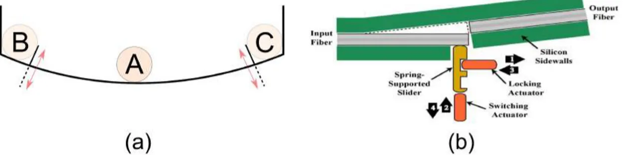
Holding via passive locking actuator Another category of the holding principles used in digital systems is the use of an external locking actuator [26, 95]. In this category, the holding function is ensured by employing a separate locking actuator that locks or unlocks the mobile part at the discrete positions. This method requires energy while locking and unlocking the mobile part, which is provided by an additional actuating mechanism, but no energy is consumed once the mobile part is locked. This holding principle is illustrated with the example of the ball on a surface as shown in Figure 1.9(a). The ball is latched in the positions B & C using an external latch-lock mechanism.
Cochran et al. [26] have developed an optical switch based on electrothermal actuators for the switching and the holding functions (Figure 1.9(b)). In the upper position of the slider, the input fiber is aligned with the output fiber (close state), while no light passes through the output fiber in the down position (open state). During the switching, the locking actuator is pulled back, the slider is switched upward or downward between two discrete positions, after that, the locking actuator is inserted in the groove to hold the slider position.