Biarritz, France, November 8 – November 10 , 2005
A Virtual Desktop’s First Evaluations for An Augmented Design
Process
Stéphane Safin 1,2, Christelle Boulanger1,2, Pierre Leclercq1
(1) : University of Liège. LuciD Group Lab for User Cognition and Intelligent Design Bat B52/3 Chemin des chevreuils, 1 B4000 Liège
Belgium
Phone : +32 4 366 95 15
(2) : University of Liège – IKU Interaction, Knowledge and Usage Research Unit Bât B32 Boulevard du Rectorat, 5 B4000 Liège
Belgium
Phone: +32 4 366 20 14 E-mail : [email protected]
Abstract: Many CAD tools already allow to design and directly manipulate ideas in a digital way. However, designers still use pen and paper during the early design phase of their projects. Indeed, existing CAD tools constraint creative work. There is a need for a spontaneous human computer interaction in design computing. In order to answer to this need, we develop an integrated aided design tool based on a Virtual Desktop. The designer sits in front of a classical desk where s/he can design and manipulate drawings and generated models. This paper describes the observations made during experiment about Virtual Desktop’s use by a designer. The experiment demonstrates that the immersive aspect of our system interface modifies the relationship between the designer and his/her model and, by the way, how this relation generates a new type of augmented interaction.
Key words: Augmented Design Process; Human Computer Interaction in Design; Sketch Based Modelling; Self-Generated Model; Building Engineering.
1- Introduction
Many CAD tools already allow to design and directly manipulate ideas in a digital way. However these tools fail to help the designer in the initial design phases, i.e. when the broad outlines of the project are defined and the decisive option chosen [1][2][3]. One of the explanation of this failure is due to the user interface, i.e. these tools require painstaking coding of precise data which is only possible once the project has largely been defined [4]. Moreover these systems place users in a circumscribed space. Their movements are reduced to mouse shifts and clicks, and their sensory interactions are limited to passive visual and auditory simulation. A second reason is related to the use of sketches widely used at the start of the design process. The sketch is used as a graphic simulation space [5]: basic elements of the project set down in the earliest drawings are progressively transformed until a definitive resolution. Each sketch represents an intermediate step from the first rough sketch to the definitive design
solution.
In current design practice, preliminary designs are essentially designed on paper before being converted into a representation in a Computer Aided Design System (CAD). Why do designers still prefer hand-drawn sketches to computer-assisted design tools at the beginning of the design process? According to Mc Call et al. [6], there are three reasons to explain it: first of all, pen and paper technique leads to abstraction and ambiguity which suit to the undeveloped sketch stage. The digital pictures, hard edged, are judged more finite and less creative than traditional sketches, fuzzy and hand-drawn. Designers need freedom, speed, ambiguity, vagueness to quickly design objects they have in mind [7]. Secondly, it is a non-destructive process — the successive drawings are progressively transformed until the final solution is reached — whereas CAD tools are used to produce objects that can be manipulated (modification, destruction, etc). Thirdly, sketching produces a wide collection of inter-related drawings, while CAD systems construct a single model isolated from the global process. Moreover, the sketch is not simply an externalisation of a supposed designer's mental image, it is also an heuristic field of exploration within the designer discovers new interpretations of his own drawing, opening up a large way to new perspectives for resolutions [8].
Therefore there is a need for a spontaneous human computer interaction in design computing. The use of a sketch-based interface should not be conceived as an improvement of the human-computer interaction but as the means to integrate computer assistance into the heart of design process [4]. In order to answer to this need, we develop an integrated aided design tool based on a Virtual Desktop. Our environment is composed of a mixed software and hardware solution which offers (i) the natural aspect of digital freehand sketching, (ii) the ability of drawing interpretation and generating a 3D model and (iii) the direct model manipulation and evaluation of performances (presently in building engineering).
Following the disappearing computer wave, the Virtual Desktop consists of an augmented virtual reality offering a reactive work space. The designer sitting in front of classical desktop and using pencil, profits from the simplicity to use a natural work space, while using virtual support, enriching the creative aspect of his work. Therefore, the system is made of two poles : the « real » pole by natural interactions’ development and the metaphor of the designer’desktop ; the « virtual » pole by interpreting its digitized sketches and the attendance of evaluators. Reality is then augmented and mixed.
While designing the software, Leclercq & Juchmes [4] have developed the concept of absent interface. This concept is part of the Disappearing Computer movement and suggests that the following 4 complementary principles should be adopted :
- Be adaptive. Although every discipline uses more or
less standardized graphic conventions, each architect has his or her own habits. The system must therefore be able to support this unconventional dialogue mode by learning the designer’s habits. For caption recognition, i.e. EsQUIsE includes a learning module that builds up an alphabet for each user. In a more general way, we can say that the computer has to adapt to human behaviour, and more specifically to the fuzzy characteristics of the sketches.
- Be transparent. A transparent interface means that the
system does not require a pre-established dialogue procedure. In our system, the designer creates freely and the IT application monitors his or her actions. The software apprehends the designer’s actions more through the context than constraining him to use predefined function.
- A designer can thus take the tool in hand without any knowledge of its functioning.
- Be natural. All a designer needs to sketch a project is
a piece of paper and a pencil. The aim of the natural interface is to conserve the simplicity of these tools, while at the same time achieving the same exceptional versatility.
- To have a common sense. A sketch is, by definition,
incomplete. The designer only uses it to represent essential information specific to the current project. He or she focuses on certain problems in succession, postponing any decisions concerning other elements of the design. To fill the information not specified by the designer, the system must be able to identify the context of the design being carried out. The system must thus be assisted by an implicit database related to the particular field of design
2- The Virtual Desktop
In order to offer the advantages of a digital environment able to help the designer while designing, without constraining him to use unnatural settings of a computer, we have developed the Virtual Desktop.
Our purposes are:
- to allow designer to work in a natural way, without
the traditional mouse and keyboard of CAD;
- to allow the designer to work in a real architectural environment with the drawing table’s dimensions; - to maintain a drawing’s high definition - four points
per millimetre square;
- to have a disappeared computer.
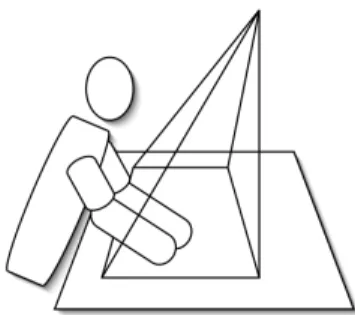
Figure 1 shows the virtual desktop in its current release
Figure 1 : Virtual Desktop
Different technical choices on the table and system of projection, and on the way of capturing lines and drawings, were made to respond to these purposes and to permit the usability of the system.
2.1 – Table and projection
The first idea was to project the working space under the table. Testings showed that projectors encumbrance made the designer’s legs position uncomfortable, did not respect the disappearing computer criteria and constraints the designer in his liberty of move. Inclined worktables are neither suitable for designing activity because the designer usually needs to work with a lot of paper sheets. So we preferred a simple horizontal whiteboard with a projection by the top.
In the first release of the Virtual Desktop, a projector is placed in a hanging ceiling with a classical mirror. To obtain a greater work surface, a second projector was placed in a later version of the Virtual Desktop. This change required to resolve a technical challenge: to manage one screen with two projectors and obtain an efficient precision of the line. To palliate the problems of picture’s gap, we changed the classical mirror for a metallic one without glasses avoiding luminous beams diffraction due to air/glass/air changes In order to clear shadows linked with a projection from the ceiling, projectors and mirror were installed to make projection inclined and to sit user out of projection cone (Figure 2).
Figure 2 : User’s position related to projection cone
2.2 – Capture system
The first release of the desktop was realised with a positioning system by infrared and ultrasound triangulation (Mimio). Two problems lead to replace it. On the one hand, the pointer, bigger than usual drawing tools, is quite difficult to handle and adds shadows areas on the drawing. On the other hand, the system has a centimetric precision which is much too low for architectural sketching.
In the second release, a selenoid digital pen has been chosen with several benefits: it is a lot finer and does not add large shadows areas; it doesn’t need a power source which makes it lighter and less bulky; it is more stable and easier to handle; it is also more accurate than Mimio pen. It perfectly matches the characteristics of an usual pen.
3- EsQUIsE
The EsQUIsE software is made up of an entry module and an interpretation module which allow to build an architectural model to inform different evaluators by the following process : to make it easier let’s describe Esquise in 3 modules. A more complete and technical explanation, mainly about the multi-agents technology which is the base of its performing may be found in our preceding papers [4], [9], [10], [11], [12],
3.1 – The entry module
The role of the entry module consists in analyzing the sketches in order to construct the geometrical model of the drawing, in other words, the internal representation of the structure of the drawing : the significant graphic elements and the relationships they maintain. The principal constraint on such a system is obviously the requirement that it should work in real time. Analysis therefore takes place in two phases. While the electronic stylus is being moved over the pad, the system captures the designer’s movements. Then, as soon as a line is finished, the system takes advantage of the time lapse available before the start of the next line to run all the procedures to synthesize and analyze the layout. The synthesis module consists of successive filters intended to extract the essential characteristics of the lines, reducing as much as possible the amount of information to be processed while conserving as faithfully as possible the appearance of the original line. To ensure that the sketch retains its « triggering potential » this step is carried out transparently for the user, who only ever works on his or her initial drawing, unaware of any interpretation being made by the system.
The categorisation function is based on a combined technique of segmentation (to differentiate and to compose packs of lines which « work together ») and of categorisation (classification of lines’ groups according to their characteristic criteria). Beyond some particular symbols (hatching, blackening, dotted lines, underlining…), the operating multi-agents system focus also on the identification of the written captions which it identifies and situates on the sketch. The aim of the analysis of the drawing is to weave the network of relationships between the different graphic objects it contains. Relationships include, for example, inclusion, intersection, proximity and superposition of lines and contours. Because the sketch is imprecise, we have developed a « fuzzy graphics » approach that takes into account a considerable margin of error in the identification of points, lines and intersections. Outlines, for example, do not need to be fully closed-off in order to be recognized. By analyzing the proximity of the ends of the lines, EsQUIsE is able to identify an imprecise outline.
3.2 – The interpretation module
The job of the interpretation module is to translate the geometrical information, produced by capturing the sketch, into a functional model of the planned architectural object. This one is generated from collected semantic properties. Lines make outlines which are translated as rooms. Other lines are recognized as letters parts of legends. Those are completed by information known by the system. For example, the word « bath » translate on the sketch the function that the designer gives to the designated space. The outline in which this word appears becomes a function-space in the architectural model with characteristics for this room : a 24°C temperature, a high humidity level and a average noise level. Those parameters, given with any designer’s intervention are used by the system to fix technological choices: the lines separating the outlines are interpreted as walls separating the rooms. Those, being characterised, are able to find out their own technological composition in order to modulate heating and humidity flows passing by the walls. Operating in the same way with the geometrical characteristics of the rooms (ceiling’s level for example) the system is able to compose in real time, a complete and cogent model of the building being designed, from some sketches drawn by the designer.
3.3 – The evaluation module
This building’s model may therefore be used as entry for several evaluations. The main one is the production of the 3D model through which the designer can virtually walk and check the representation of the dimensions and spaces he thought of. EsQUIsE is also able to use this model to estimate the energetic performances of the future building and so give the designer a good idea of his choices’ opportunity. Simulating the solar source, knowing the ordered temperatures for each room and each wall’s composition, this second module may estimate the needs in heating and air-conditioning the building will need.
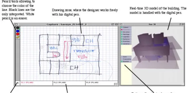
Figure 3 illustrates Esquise interface. The designer disposes of a drawing area on wich he can freely work. He may
choose between several lines colors. However, only black lines are interpreted by the system. Colored lines are used for annotations and decorations. They are present in 2D on the model work and may be hidden. The designer can add tracing papers. Each created tracing paper having at least a black line is considered as a floor. If they only have colored lines, they
are not a floor: they form a tracing paper of decoration on the work model. The tracing papers appear like tabs in bottom of the window and can be selected constantly. A window allows to display evaluations (3D work model, thermal efficiency, energetic needs).
Figure 3 : EsQUIsE Interface
4- Experiment
The device was tested in real situation in order to evaluate the system’s usability by an ergonomic approach and to explore aspects related to the immersion in the Virtual desktop environment.
We compared two designers in two different situations : one traditionally designing with paper and pencil ; the other one working on the virtual desktop (figures 4 and 5 illustrate these devices).
4.1 – “Classical” environment pen/paper
The designer does not have particular order but a drawing space allowing the video capture of the process. He has paper sheets, a roller of tracing paper, several pencils and highlighters as well as slats, a square and a calculator.
Figure 4 : Pen/paper setting
4.2 – Virtual desktop with EsQUIsE interface
The designer works on the Virtual Desktop running EsQUIse software. He has a digital pen with a virtual pallet allowing to use several colors. A single system simulator — 3D model — is running all the time. He has the possibility to use other tools as slat and squares.
Figure 5 : Virtual Desktop setting
Each designer has been observed by two types of observers: a student in architectural sciences and a work psychologist. Activities were integrally filmed in 2 views: a frontal view allowing to apprehend all the space and a high angle shooting allowing to follow drawings designing. The activity’s aim is to design a school in 4 hours maximum. The orders are the same for each student. Specific constraints for the building are:
- An urban prescription: roofs must be plates so EsQUIse software is able to interpret the sketches and to make a model;
- A very big tree and two plateaus separated by a three meters step in rock related to the ground and the floors;
- Specific constraints in terms of adjacency and surfaces of various spaces.
4- Analysis
Video data have been analysed by ergonomists – work psychologists to respond to the experience’s aims. This analyse is essentially exploratory. Many criteria have been defined to pilot the video observations:
- An interactions modalities definition: how does the designer interact with the system (papers or virtual tracing papers)? Are interactions fluid or flexible?
- An observation centered on the interface. It includes an analysis which is some times critical allowing to see the difficulties related to the interface. It also includes an analysis by focus of attention to understand when user’s attention is more carried on the system more than on the designing content, with the purpose to strengthen the natural aspect of the interface.
- An exploration of the aspects related to the immersion in the virtual desktop. It’s mainly a gestures analysis in the two environments.
- An analysis of the use of the 3D model constructed in real time by the software. Went is this model used, an for which aims?
5- Results
5.1 – Interactions modalities
Some conclusions can be done specifically to the virtual desktop. On one hand, the apprehension of the system by the user seems natural: he or she feels very quickly comfortable on the virtual desktop. The user doesn’t need more than half an
hour to learn how to use the system. On the other hand, even though the projection resolution is much lower than the tablet one, the sketches have a sufficient level of details. However we notice that the scale of the drawing is bigger.
Activities comparison showed us the importance of the design environment flexibility. The pencil paper environment is very flexible. Several pens can be used, the supports (tracing paper and drawing paper) are neither limited in their format, nor in number. It allows a very free arrangement of the papers which can be turned upside down and moved simply with the hand.
In the virtual desktop environment, some interactions may seem to be constraining: .
- Only one kind of support is available for the designer: the virtual tracing paper;
- The designer is able to change the dimensions of the tracing papers window but not each tracing paper;
- All the tracing papers are attached and it is not possible to make a translation from a tracing paper to an other;
Only one kind of pencil is available
Nevertheless it appears that designing a tracing paper is very simple (one clic) and that the range of their superposition could be changed simply dragging tracing papers’ icons. In this activity, the designer mainly works with a red pencil. Black – the only color interpreted by the system – is only used for the drawing’s beautification.
Therefore quickly appear in this activity a kind of tracing papers’ specialisation: draft tracing papers in red and final tracing papers in black.
Those last one appear cleaner than the first one: the line is straighter; each line represents a wall and each wall is represented by a line. On those tracing papers, the designer often uses the digital eraser. It is only at the end of the activity that the designer annotates his final tracing paper with red lines.
5.2 – Immersion
An essential point of the comparison between the three activities lies in the sketches exploration methods. The drawings exploration is indeed an important element of the architectural conception. Having new points of view on the drawing provides the emergence of unexpected discoveries [13] and of what Goel [14] calls « lateral transformations», i.e. the movement from an idea to another.
In the three activities, the sketches are explored by the architects. There is movements on the paper sheet, allowing expressing intention, especially in terms of persons circulation and space dynamics. Nevertheless, these important explorations for the formalization and the expression of the non-graphic ideas reveals a different aspect on the two types of holders. In the paper activity, the sketches are explored with the pen: certain elements are pointed to bring them to the fore in the architect reasoning
and the pen is often in movement to explore the circulations in the space or certain dynamic concepts.
Figures 6 : Exploration by pointing on paper/pen
In the virtual desktop activity, even though these methods of explorations are present, we notice also a bigger corporal investment in the drawing: several times, it is the whole hand that allows the expression of a movement and the use of the two hands allows a space delimitation or a intention expression related to a surface (see figure 7 and 8). This can be explained, on one hand, by the bigger size of the drawing in virtual desktop, but also, by the immersive aspect of the system. In fact, several factors facilitate the immersion in the virtual desktop :
- The work surface luminosity, contrasted with the darker environment of the room.
- The environment “including aspect”, where the designer is placed between a table and a suspended ceiling, in a delimited space and explicitly dedicated to the design.
- The presence of a big size and coloured dynamic 3D-model, contributing to a work space specialization and keeping the user’s attention on the system.
Figures 7 & 8: Exploration by hand movement and space delimitation
with two hands in the Virtual Desktop
5.3 – Interface’s ergonomics
Several problems of the EsQUIsE interface were found during the testing:
- Incoherence
In this system, the 3D model is built in real-time. The virtual tracing papers have to be placed in the right order in the tracing paper arrangement zone (the horizontal zone under the drawing zone) in order to constitute the floors: downstairs on the left and upstairs on the right. Furthermore, in order to work with an underside plan (with a active tracing paper and another in transparency), the tracing papers must be arranged in a specific way in the zone: the tracing paper visible in transparency is
automatically the one on the right of the active tracing paper. This leads to a coherence problem in the arrangement of the tracing papers: the tracing paper which is visible in underside plan at one time corresponds to the upper floor of the 3D model. This does not correspond to the working habits of the architects who usually base their drawings on the lower floor. This aspect of the arrangement zone leads to some problems in our testing.
- Structuring constraints
The building has to be created on several floors in parallel. From an only plan, it is not possible to have a projection on several floors. It is then necessary to draw all the floors very soon in the design process in order to have a early volumic building representation.
All the virtual tracing papers are interpreted to build the 3D model, and there is no possibility to hide them. When a drawing paper contains a black line (the coloured ones are not interpreted), the paper constitute a floor in the 3D model. It is therefore impossible to have two versions of the same floor’s sketch without having twice the same floor in the model. It is thus necessary for the user to delete the old version of the floor to make another version. This leads the digital sketch to be quite different of the « natural » sketches. Indeed, MacCall et al. [6] define the non-destructiveness character of the sketch as an essential characteristic. Furthermore, this problem of destructivity reduces the possibilities of trials-and-mistakes work, essential element of the design.
As we have already told in the chapter about the interaction modalities, it is not possible to modify the relative size and the relative arrangement of the tracing papers. The drawings always superpose in the same way, and always have the same size. It is not possible to stagger a tracing paper from another.
Finally, it exists an only type of support in the software EsQUIsE, the transparent tracing paper, while the use of matt sheets of paper is frequent in other activities. Moreover, the transparency is on an only tracing paper. 5.4- Using 3D
T
he presence of a 3D model in the Virtual Desktop, in immersion and accessible at every moment, induces the user, by these affordances, to center his activities on this model. We therefore observe that the design strategy has a different aspect on the Virtual Desktop : the lay-out has a central role and all the floors are designed together, in parallel, contrarily to the activity pen and paper where the first floor, primary designed, is used as the bottom for the realisation of the other floors6 – Discussion
After these observations, several evolutions are planned for the Virtual Desktop and for EsQUIsE.
In order to guarantee the system flexibility which is important to privilege the ideas emergence and the unexpected findings [14], several projects are starting concerning the Virtual Desktop:
In order to strengthen the natural feature of the Human-Machine interaction of the device, it is essential to extend the desktop metaphor and to take into account the hand gestures that have an important role in the documents manipulation. In that objective IDIMAGE project tries to develop the algorithms that allow to follow the hand gestures in real time from a video capture of the desktop surface.The project objective consists of the specification and the realisation of a natural manual interface which allows the entire and transparent integration of the hand gestures for the virtual sheets of paper manipulation from a computer vision device. Moreover, in order to improve the system and to develop new possibilities, we are also trying to understand the collaboration aspects of design : collaboration for learning, collaboration between architects and other professionals for an integrated design and collaboration between the architect and his client sharing a 3D model.
The objective is to develop the Virtual Desktop for an augmented collective use in coattendance or remotely.
6.2 – Evolutions of the EsQUIsE software
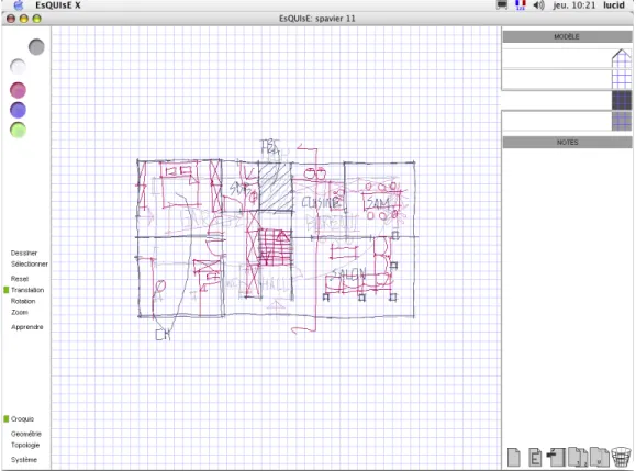
The following aspects of the software EsQUIsE interface were modified to follow the ergonomists recommendations proposed after the experiment (figure 9) :
- The incoherence problem of the tracing papers arrangement has been solved with a vertical disposition of
these tracing papers : the disposition is clearer for the user and the floors disposition in the model does not cause any confusion anymore due to its analogical aspect. - The actions on the tracing papers have been
multiplied : it is now possible to duplicate a tracing paper with a simple clic.
- Concerning the impossibility to dispose several different drawing supports, a transparency regulation has been implemented : it allows to change an opaque paper (as a sheet of paper) in a translucent paper as a tracing paper or a completely transparent paper.
- Concerning the possibility to modify tracing papers position and size, a translation function, a rotation function and a zoom function have been implemented. It is a real system improvement for paper supports : with the translation function, the sheet has now an infinite size. The zoom function allows to work the global aspects of the sketch but also the more accurate details, which is impossible on a sheet of paper. If these functions are relatively classical in CAD systems, the originality is that these actions do not act on the drawing but on the holders (virtual sheets of paper).
- The tracing paper zone has been divided in two parts : one part where the tracing papers are interpreted by the system (to construct the 3D model) and a second zone where the tracing papers are not interpreted : the « Notes » zone. It especially allows to create and to keep several versions of the building and to change very easily in the model with a simple slippage of the tracing papers towards the « Model » zone.
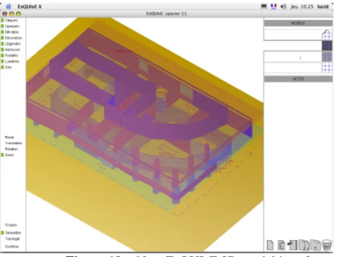
- Finally, we have particularly paid attention to the system coherence. Indeed, the system includes separated windows for the sketch, for the model and for the topological graph (figures 9,10 and 11) . These three windows include the same
characteristics: an action zone on the content, a navigation zone (translation, zoom,…) and a zone to call the different windows. These three zones are on the left side of the interface
Figure 10 : New EsQUIsE 3D model interface
Figure 11 : New EsQUIsE topological graph interface
The changes of EsQUIsE interface and of the virtual environment lead to an increase of the architectural sketch support, to a virtual paper keeping the polyvalence and flexibility characteristics of the real paper, and at the same time it is augmented by an interpretation of the drawing.
6.3 – Future investigations
The next step of our investigations is the implementation of a test situation to check the aspects linked to the immersion on the Virtual Desktop.We intend to implement a test situation in order to compare an activity on the Virtual Desktop and a situation with the software EsQUIsE on a screen tablet.
This allows us to make observations and conclusions specifically linked to the immersive aspects of the Virtual Desktop.
7 – Acknowledgments
We thank the Faculty of Applied Sciences of the University of Liège that has financed the Virtual Desktop.
8 – References
[1] Gross, M. The Electronic Coktail Napkin, Working with Diagrams. Design Studies, Vol. 17, 1996, pp.53-69
[2] Suwa, M. & Tverski, B. What Architects see in their Design Sketches : implications for design tools. In Proceedings of ACM Conf. On Human Factors in Computing Systems CHI’96, ACM Press, New York, 1996, pp. 191-192. [3] Aliakseyeu, D. & Martens, J-B. Physical paper as the user interface for an architectural design tool. In Proceedings of INTERACT 2001, Tokyo, Japan, July 2001, pp. 680-681. [4] Leclercq, P. and Juchmes, R. The Absent Interface in Design Engineering. AIEDAM Artificial Intelligence in Engineering Design and manufacturing. Special issue : Human Computer Interaction in Engineering Contexts, Vol.16, n°5, Cambridge university Press, November 2002. [5] Lebahar, J. Le dessin d’architecte. Simulation graphique et réduction d’incertitude. Editions Parenthèses, Paris, 1983. [6] MacCall, R., Ekaterini, V. & Zabel, J. Conceptual Design as Hypersketching. In Proceedings of the 9th Int. Conference CAAD Futures, Kluwer Academic Publishers, Dordrecht, The Nederlands, 2001, pp. 285-298.
[7] Aliakseyeu, D. Direct manipulation interface for architectural design tools. Conference on Human Factors in Computing Systems, CHI '02 extended abstracts on Human factors in computing systems. Minneapolis, Minnesota, USA, 2002, pp. 536-537.
[8] Goldschmidt, G. The Dialectics of sketching. Design Studies, Vol. 4, 1991, pp. 123-143.
[9]Juchmes, R., Leclercq, P & Azar, S. A multi-Agent System for Architectural Sketches Interpretation.
Eurographics Workshop on Sketch-Based interfaces and Modeling, Grenoble, France, 2004, pp 53-62
[10]Leclercq, P. Interpretative Tool for architectural sketches. First International Roundtable Conference on
Visual and Spatial Reasoning in Design : computational and cognitives approaches. MIT, Cambridge, USA, Key center
for Design Computing, Sydney, Australia. 1999, pp 69-80. [11]Leclercq, P. Programming and Assisted Sketching, Graphic and Parametric Integration in Architectural Design.
CAAD Futures, Eindhoven University of Technology, ND,
Kluwer Academic Publishers , Dordrecht, Boston, London, 2001.
[12]Leclercq, P. Invisible Sketch Interface in Architectural Engineering. Graphic recognition, recent Advanced and
Perspectives, Lecture Notes in Computer Science. LNCS
3088, Springer Verlag, Berlin. 2004, pp353-363
[13] Suwa, M., Gero, J.C. & Purcell, T. Unexpected discoveries and S-invention of design requirements: important vehicles for a design process. Design Studies, Vol. 21, 2000, pp. 539-567.
[14] Goel, V. Sketches of Thought. Bradford-MIT Press, Cambridge, 1995.