PINCII POINT METIIOD IN OPTIMIZATION OF ADVANCED COMBINED CYCLES F. Maréchal, M.-N. Dumont, B. Kalitventzeff
Laboratoire d'Analyse_,et de synthèse des systèmes chimiques Université of Liège
Sart Tilman - B6a B-4000 Liège
ABSTRACT The pinch point method ha.s been developed to identify energy saving opportunities in industrial processes, The use of the composite curres allows to compute the minimum energy requiremcnt of a process and to determine optîmal heat exchange between hot urd cold streams. The use of MILP (Mixed Integer Linear Programming) optimiTation method allows - to extend the approach to solve combined heat md power problems. The method is applied here to determine the optimal cor-tfiguration of combined cycles, It allows to maximize the mechanical power production without having to consider the heat exchangers configuration in the boitir nor in the preheating section. The method is also used to compute the steam extractions or productions and their optimal pressure levels that maximize the mechanical power produced From these results, the heat exchangers network structure is then determined. Three situations ae analyzed : l) the heat recwery in a classical boiler using air preheating, 2) the gas turbine combined cycle and. 3) tlæ " isothermal" gas turbine. The " isotlærmal" gas turbine is an innovative promising technology that uses a partial ortdation reactorfollowed by a staged combustion bàtween the expansion stages to reath a quasi isothermal prortle (unng the expansion. This allows to reduce the exàrgy losses in the gas turbine. The resulting flue gases are rnid in a combined cycle optimized with the method presented here. Dffirent configurations are discussed We show tlnt the structure of combined cycles may strongly dffir front one to another.
INTRODUCTION
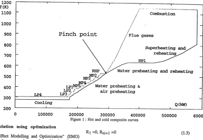
The pinch point based methods have been developed to identify energy saving opportunities in industrial processes. lhe pinch point principle has been first suggested by Hohmann [1] in the beginning of the 70ies, the relaûed methods have been largely developed during the 80ies [2]. The basic principle of this method is to use the enthalpy/temperature diagran (figure 1). Such diagrams are built by cumulating the content (quantity) of all the heat sources (hot steams) and of all the heat requirements (cold sfreams) according to their temperature level (quality). In this diagram, there is a point where the tempemture difference between hot steans and cold streams is minimum; this point is named the pinch point. The value of the smallest acceptable temperature difference (Dûnin) is fixed in order to limit the investment required for the heat exchangers. The identification of the pinch point gives valuable results for the engineers in order to modiff the process and optimize the use of energy in the process. It defines the overall energy balance ofthe system and the area between the hot and the cold composite curves is a measure
of the exergy losses. The temperahlre difference at the pinch point defines the minimum hot utility requirement, the cold utility and the total amount of recoverable heat using countercurrent heat exchange.
One advantage of the method is to represent in a enthalpy/temperature diagram the heat exchange between hot and cold streams in the system (figure 1). The analysis of the shape the such curvos allows to identi$ ttre possible improvements to be made in the process.
Another interest of the. approach is the possibility of solving the pinch point problems by using linear programming algorithms. The research work in the field was pioneered by Cerda et al. [3] and papoulias ard Grossmann [4] These formulations are based on the definition of the heat cascade. After a correction of the temperatures of the hot and cold steams to account for Dtmin contribution of each stream, a heat balance is written for each temperatue interval by summing up the heat coming from the hot sheams in the interval and the heat coming from the upper temperature intervals md subtracting the heat required by the cold steams in the tempemture interval and the heat cascaded to the lower temperature intervals. Of course, the cascaded heat must be equal or greater than zero for all the temperatue intervals. This allows to define a set of linear equatons that model the ideal heat exchangers network between the hot and the cold streams. The interest of the approach is to allow the computation of the network without having to define the structure of the heat exchangers, i.e, the interconnections between hot and cold steams.
METHODOLOGY
Considering that power plants are composed of hot and cold streams, the idea is to apply a pinch point based method to. analyse and optimize the production of elestricity. The major difference between indushial processes and power plants is that hot and cold strearns are not fixed and that flowrates and temperatures in the system have to be optimized in such a way that the optimal efficiency is reached. The use of linear programming allows to tackle the problem of flowrates optimization, while the problem of temperatures or pressure optimization will be sôlved by analysis and discretisation. Theprinciple of the approach is to define aprocess superstxucture that includes the possible operations to be analysed and to extact optimal process configurations from the supenftucture.
1200 T(K) 1100 1000 900 800 700 600 500 400 300 200 100000 200000 3 0 0 0 0 0 4 0 0 0 0 0 500000 6000(
Figure I : Hot and cold composite curves Generate solution using optimization
Using the "Effect Modelling and Optimization" @MO) approach [7], the power plants and combined cycles are represented by a set of interconnected operations: combustion, air preheating, expansion, steam condensation, steamproduction, air or wâier cooling, etc... Each operation defines hot and cold sheams (heat effects) whose inlet and outlet temperatures are considered as a characteristic of the operation. Their intensities (flowrates) have to be computed in order to satisfy the mechanical power requirements of the power plant at minimum cost. The interconnections between the operations are of different types considered separately and define the modelling equations. Each heat effect (i,e, energy requirement or production) intoduces its own contribution) in the heat cæcade defined by the constaints (1.1 to 1,2). Linear equality and inequality constaints are used to define material balances as well as some modelling equations. The process is therefore defined as a superstructure of interconnected operations. A paxt the necessity of computing the extent of usage of each operation, one has also to compute whether an operation is useful or not. The selection of the operation w is defined by an inûeger variable yw md the constaints (1.4). The extent of usage of the operation w is computed by the multiplication factor f* that multiplies all the effects associated with the operation w. The constraints (1.3) are inEoduced to impose the overall heat balance of the process. The cost effect appears in the objective function with a proportional term C2ys Iinked to f1,y and a fixed cost Cl* linked to y*.
nw
I ( f * g w t < ) + R t + l *Rk=0 V k = l , . . . . , n i ( 1 . 1 ) i=1
R t > o
Rl =0, Rni+l =0
fminry y*S fw 3 fmax* y*
(1.3) V 1v=1,...,n* (1.4) IVith n1 n$, R1 r w 9wk y w € {0,1}
the number of temperature intervals; the number of alternative operations;
the heat cascaded from the temperature interval k to the lower one;
the multiplication factor of the effects linked with the operation w;
the heat load of the thermal effects of tre operation w in the temperature interval k. gwk > 0 for a hot stream and < 0 for a cold stream;
the integer variable linked with the use of the operauon w.
yw =1 if it is used, yw = 0 if not;
fmin*, foiax* respectively the minimum and maximum values accepted for f* if yq,=l. A subset of linear equations (2.1 - 2.2) is added to model the links between the different operations, i.e. the stearn extraction, steam superheating,.., These equations ate written in such a way that heat balances are verified with respect to the thermal effects defined. The detailed formulation used to model the steam./water cycle is given in Marechal F. [5].
n.ry nr
I (ui* f.,;y+c;,y yw ) +I dlxr=bi V i=|,.,.,ne Q.l)
nel el
Cornbustion
Pinch point
SæerneaLing and
HP1
RIp _\Z Water preheaÈing and relreatsing
ww7
*r*. *Yy'*
^Èer
preheab
ins &
W4 /-/
air pretreaEing
L P 3 , j
CooLing
a(]er)
llv
I (uj* fiv +cjw yw) w=1
Xmint( X1 ( xmax,
dir xr ) bi Y i=1,...,nie(2.2)
V e l , . . . , n , Q . 3 ) with ne the number of effects modelling equality
constraints;
nie the number of effects modelling inequality constaints;
nr the number of additional linear variables; x1 the additional variable r used to model the
effects of the operation;
âiw, ciw respectively the coefficients of the flowrates and the integer variables ofoperation w in the constraint i in the effect models. ( refers to inequality constaints);
d;, bi respectively the coefficienrs ofthe additional variables and the independent term in the consfraint i in the effect models; x1 the additional variables used to model the
effects of the operation;
xmiry, xmaxrrespectively the minimum and maximum bounds of xr.
In addition to the heat effects, one has to consider the qtfgcts of mechanical power consumption and production. This is compuûed by adding a mechanical power balance (3). The cost contribution of export (C") being added to the objective function.
W1y - Ws1 =0 w=1
with wyy the mechanical power produced by the
operation w calculated for a reference flowrate: ww ( 0 for a consumption and > 0 for a production;
wel the production of electricity.
APPLICATION
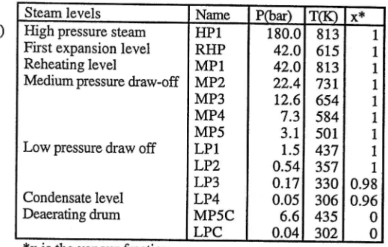
Let us illustate the use of the approach to analyse classical power plants and combined cycles. Table I gives the only necessary data used to define the water cycle and the combustion in the model. The temperatures are those measured on an existing classical power plant using coal. In the power plant superstructure, all the possible expansions are considered and only the most efftcient one will be selected.
The composite curves of the classical power plant used æ reference are given on figure 1. The ICC (ntegrated Composite Curves) [6] of the water cycle (figure Zj is a more convenient way for the visualisation of the water cycle integration. In this figure the composite of all the hot and cold sheams of the water cycle is matched to the composite curve of the hot and cold steams of the fumes and air preheating system. The rnechanical power produced is represented by the balance between the hot and the cold streams of the water cycle. On the figure, we have represented the expansion from HPL to RHp, from Mpl to the condensing levels (LP4) and the mechanical power produced by expanding from MPl each of the steam extraction flowrates.
' Ilr
r=l
*x is the vapour fraction Classical power plant
1200 T l r l 1100 tmo 900 800 7 0 0 6 0 0 500 a o o 3 0 0 2 ô 0 * -50000 (3) Ilv :, fw
o 50000 10æ00 1500æ 2ôoooo ts@oo !m@o 350to
o{'Ûn
Figure 2 : Integrated composite curves of the system in the actual situation
On figure 2, one can observe that only one pinch point is activated, It corresponds to the steam extraction RHP, The fact that no other pinch point is created indicates that the other steam extractions should be increased in order to reach the fixed DTmin in the exchangers. This value is defined as a technological conshaint defining the minimum temperature difference accepæd in a heat exchanger. The value is DTmin=2oC for the exchangers in the water cycle, 260C for the exchangen between the flue gases and the water cycle, 50oC for the exchangers between air and flue gases and 260C for exchangers between steam and air. The small value of DTmin in the water cycle is explained by the fact that heat recovery by injection (DTmin=0) is possible. In the optimal situation, each exFaction flowrate should be maximised in such a way that it creates a pinch
Steam levels Name Pôar) T(IO x'F
High pressure steam First expansion level Reheating level
Medium pressure draw-off
Low pressure draw off
Condensate level Deaerating drum HPl RHP M P 1 MP2 MP3 MP4 MP5 LPl LP2 LP3 LP4 MP5C LPC 180.0 42.0 42.0 22.4 12.6 7.3 3 . 1 1 . 5 0.54 0 . t 7 0.05 6.6 0.04 8 1 3 6 1 5 8 1 3
73r
6s4
584 501 437 357 330 306 435 302 I I I 1 I I 1 I L 0.98 0.96 0 0Classical cycle r acÈua] flffiaÈêr
Table 1 : data used for thc
LIIV: Lower Heating Value Cooling system at 288K
LHV 49589 25450 kJ/kg
Airrequirement(fs) 1.6.97 7.23 kg air/kg Adiabatic temperature 2329 Zll,I K
point, When pinch points are not created, the energy potential (i.e. the exergy) is not well exploited. At the system level, this means that part of the energy of the fumes is directly sent to the cooiing system without producing mechanical power.
clasrtcal cycl€ : oDÈfulzeal flffiat€ &d alr preheâEbg
l:læ I(f,I lt00 1000 900 900 too 500 500 t00 t00 200
condensation level and Ext refers to the mechanical power production related to the extractions.
Combined cycles
Combined cycles are composed of a gas turbine and a water cycle to recover the heat at the outlet of the turbine. Two effects are considered to model the gas turbine: the fuel ard the air. The link between the two effects is the heat balance of the burner as shown on figure 4, the heat of the fuel has to be used to satisfy the energy requirement of the air at the outlet of the burner. This is the well known effect of dilution to reach the limit temperature at the inlet of the turbine. The data given on figure 4 have been computed using a simulation model for a gas turbine workjng at 10 bar. The fuel effects relate to I kg of natural gas, the air effects relate to one kmol of air. The efEciency is 34 Vo. If. we \ryant to represent a standaxd con{iguration of a gas turbine, we will define the airpreheating demand at 1373 K and the only possible way of satisfying the heat is by the combustion. On the other hand if we accept to optimize the gas turbine operation, we will define the air preheating as a cold stream to be heated from the outlet of the compressor to the inlet of the turbine introducing in the supesfructure the possibility of using a regenerative heat exchange. In
-50000 0 5O0OO 100000 1500m t0æ00 250000 !m000 35000ô
aûm
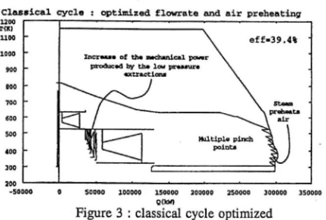
Figure 3 : classical cycle optimized
The ICC of the optimized situation are given on figure 3. 'We can observe that each steam extraction is used at its maximum level. Steam extaction is used to preheat steam and, in the optimal situation, to preheat air. In the optimal situation, we have considered air preheating up to the ûemperature of the first exfraction (615-25 = 590 K) to account for the effect of heat pumping of the air preheating. Using effect modelling, air preheating is computed in the following way. lVhen considering the combustion, one can consider that the LlfV can be divided into two parts: Qr in the radiation zone (above 1173 K) and Qc in the convection zone from lI73 to 298K. The heat available in the radiation zone is constitued by the heat ofreaction (QR) and the energy required to preheat fuel (QD and the air of combustion (Qa) from the ambient condirions (298K) to 1173 K. 'TVhen air (and/or fuel) is preheated, the heat for ù preheating is smaller and therefore the heat available in the radiation zone is increased. Air preheating should be perfomred using heat that is not useful to produce high pressure steam, otherwize, the heat required for ù preheating is not useful for producing steam (in reality, the heat of preheating is rccovered and the balance is zero). If we consider the first extaction of steam, the heat of condensation may be used to preheat air and therefore to increase the production of high pressure steam (above the first pinch point), the balance is an exta amount of mechanical power production in the expansion. In reality, air preheating might be perfomred by using steam or by using flue gases; ifit is the first solution then the exchange between flue gases and water preheating is increased, in the second case, the exta steam extaction is used to preheat water. This is an advantage of the approach, the heat exchanger network is deterrrined afterwards, but we are sure that there exists at leæt one process configuration with at least the fixed DTmin in all the exchangers. Table 2 gives the results of different alternatives. BASE refers to the actual situation with air preheating to 436 K. OPT refers to the optimized steam cycle and a combuston wittrout air preheating, OPTR refers to the situation with optimal ù preheating and steam cycle. Column eff refers to the oyerall efEciency, IIP is the high pressure expansion, MP is the expansion from the reheating level (MPl) to the
1599 kJe/ksNC
835 r( 2498 kitlksNc
Figure 4 : effect model ofthe gæ turbine
The list of steam levels has been considered as being the one used in the classical cycle analysis. An additional level at 7l bar (HP) has been added to be able to represent the new combined cycles installed in Belgium [9]. IVe have to insist on the fact that both steam production and steam consumption are allowed in the model. Figure 5 left gives the ICC of the water cycle conesponding to the classical gas turbine optimisation. One can observe that the MPl level is chosen as the highest pressure level. Steam is produced at different pressure levels in order to recover the energy of the flue gases. Furthermore, steam extractions from the turbine at the levels LPl and LP2 are used below the stack tempemture to preheat the water in the cycle, Figure 5 right gives the ICC of the steam cycle where only IIP and MP4 levels have been allowed. In this case, the efficiency is lower, the steam flowrates are optimized and
Table 2: results
39,lVo 27,59Vo 6L,07Vo II,34Vo 38.6Vo 26,57Vo 65,58Vo 7,86Vo
4Vo 27,77Vo 6l,75Vo I
lærs. ol tù. Érûql fr ttdsd!!| tL ldt@.
the MP4 level is used to valorize the excess of energy available in the fumes due to the air excess. When steam may be injected in the gas turbine, the steam production for the gas turbine is preferred to the MP4 level production. This is not the case when the multistage steam production is allowed. In the optimal situation, multipressure levels are used in the boiler. The use of integer variables in (1.4) allows to limit the number of levels by imposing a minimum flowrate for each new production level added This will allow to avoid the generation of solutions with very small flowrates. In this case, the use of integer cuts pl allows to generate multiple process configurations and therefore obtain automatically the differential benefit of adding or not a pressure level,
Table 3 gives the comparison of the three alternatives studied here above. EFF is the global efftciency of the elecûicity production, GT is the efEciency of the gas turbine and Steam is the proportion of electricity produced by the steam cycle.
Advanced combined cycles
The isothermal turbine (figure 7) is an innovative promising technology [10] that uses a partial oxidation reactor followed by a staged combustion between the expansion stages to reach a quasi isothennal profile dr:ring the expansion. The resulting flue gases have low air excesi and therefore will produce lower losses at the stack. The staged combustion allows to reduce the exergy losses all along the gas turbine.
900 ttrt 800 ?00 600 500 400 t00 400 1200 1 { R } 1000
Figure 5: optimal combined cycle
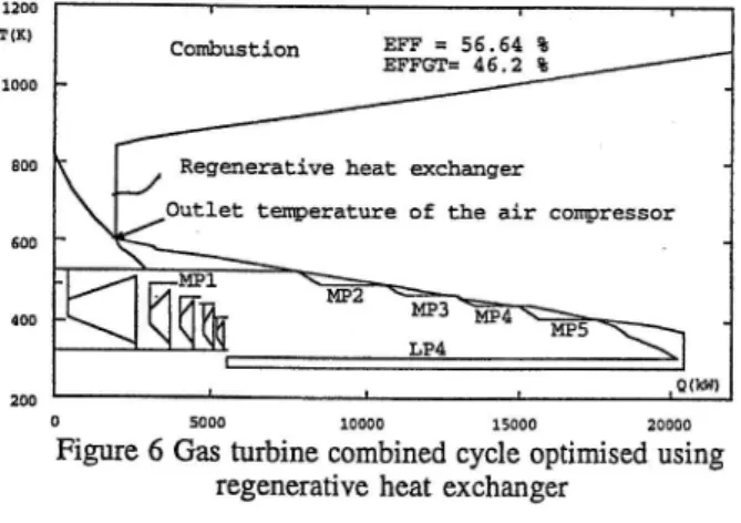
The curves of figure 6 result from the optimization where a regenerative exchange between fumes and air is allowed. In this case, the air flowrate is optimized and we should note that the temperature at the outlet of the compressor creates a pinch point. Above this point, steam superheating and regenerative heat exchange take place. 'When a regenerative heat exchange is used the air excess is increased and therefore the steam cycle has to be adapted. With respect to the optimal situation, the production of steam at the different pressure levels is more staged and the steam exhaction is not used since enough heat remains available in the fumes below the temperature of MP5 to preheat the water of the steam cycle.
The use of the method presented here allows to optimize the steam cycle and the steam production to be integrated to the flue gases of the turbine. This approach is of prime importance since the efficiency of the gas turbine and the flue gases composition will vary according to the steam injection in the reactor. The steam injection is required to a given extent to avoid the formation of coke in the catalytic teactor. The effrciency of the gas turbine increases from 46.5Vo Io 58.980 when the ratio steam,/CH4 varies from 0.4 to 3. These values have been computed for a maximum pressure of 60 bar and a turbine inlet temperature of 1673K. Those values are the one proposed by the Gas Research Institute to comparc the gas turbines technologies. Due to the reactions limited by an equilibrium, it becomes very difficult to represent the optimization of the turbine using the linear equatons used in the EMO model. For this reason, we have used the BMO only to compute the optimal stearn cycle to be matched to the flue gases of the turbine. The flowrate, the composition and the temperature of the flue gases as well as the mechanical power production have been computed using the modelling tool VAII û [11] that allows a rigorous computation of the reactions. As steam is injected in the gas turbine, it has to be produced by heat exchange that will be added in the list of cold streams, Table 7 gives the comparison of the different steam injections considered. The steam cycle is identical to the one used in the previous examples. The only difference is that we have dded a steam level corresponding to the steam requirement of the gas turbine. Steam/CH4 is the molar ratio of steam versus methane, ToT is the temperature at the outlet of the isothermal
o 5000 10000 15000 2ooo0
Figure 6 Gas turbine combined cycle optimised using regenerative heat exchanger
ODtlirized EÈer clrcl€ EFFr 51,15t EPFGI = 33.?$ lIP 70b sd L? 7b crâter 8FF= 50 t EFFGif c 33.?t
Àir Waler Stean Ctt{ 18.lks 1.s8ks 1..l8ks lks
zs'rx s6'lx sïsx
Figure 7: The isothermal gas turbine configuration
Conbustion EFF = 56.54 t EFIGT= 46.2 *
RegeneratLve heat qcbæger
OuÈlet te[E)eratEe of the air compresso!
ts for the classical combined
EFF GT Steam GTEST GTOPT GTROPT 49,98V0 33,7V0 33,83Vo 51,,167o 33,7V0 35,357o 56,657o 46.2Vo 1,9.15Vo Table 3 resul for the
turbine, Eff is the overall efSciency of the electicity production, GT is the efficienc$ of the gas turbine and Steam is the proportion ofltrezirechanical power produced by the steam cycle.
'l'able 7: ettrciencies of the advanced combined
Stear/CH4 ToT(K) Eff GT Steam
0.43 0.87 t.32 3.09
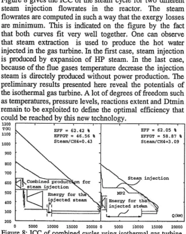
1153 62,42Vo 46,567o 25,4lVo 1085 62,67V0 48,697o 22,3lVo l02l 62,6970 50,84Vo I8,90Vo 813 62,A5Vo 58,87Vo 5,l2Vo Figure 8 gives the ICC of the steam cycle for two different steam injection flowrates in the reactor. The steam flowrates are computed in such a way that the exergy losses are minimum. This is indicated on the figure by the fact that both curves fit very well together, One can observe that steam extaction is used to produce the hot waûer injected in the gas turbine. In the first case, steam injection is produced by expansion of HP steam. In the last case, because ofthe flue gases temperature decrease the injection steam is directely produced without power production. The prelirninary results presented here reveal the potentials of the isothermal gas turbine. A lot of degrees of freedom such as temperatures, pressure levels, reactions extent and Dtmin remain to be exploited to define the optimal efficiency that could be reached by this new technology.
1200 T(IO 1100 1000 900 800 700 500 s00 {00 300 200
0 5000 10000 15000 2oooo o 5000 ioooo 15ooo 2oooo
Figure 8: ICC of combined cycles using isothermal gas turbine
C O N C L U S I O N S
The application of a pinch point based method using MILP optimization has been applied to analyse the integration of the different elements constituting combined cycles. The identification of the different effects that should be considered in a given technology allows to identify possible process improvements and to understand their implication on the other units of the system. The interest of the approach proposed is the usage of a simple model that allows to represent the ideal heat exchanger network without having to make assumptions concerning the interconnections between the different heat exchangers. Of course once a process configuration has been chosen, the heat exchanger network including the heat exchange between water, steam and flue gases should be designed and all the values should be optimized using a non linear and more rigorous model. The graphical representation proposed to visualise the results of the optimization allows to understand the integration of the different elements in the
system and shows the way chosen to maximize the electical efficiency of the process. Using the proposed approach, we have optimized the production of different types of power plants, from the classical production to the combined cycle using an isothermal gas turbine. \Me demonsûate the benefits that should be obtained by using the proposed approach in terms of understanding and in terms of efficiency increase. We demonstate as well that modifying a gas turbine technology requires the adaptation of the water loop of the combined cycle in order to maximize the valorisation of the low temperature heat of the flue gases.
ACKNO\ryLEDGEMENT
The authors wish to express their thanks to the Rector of the University of Liège, the government of the 'Communauté Française de Belgique' and ELECTRABEL for financing the redaction of this publication, and to the Commission of the European Union (DG)ff) for financing our RT&D activities in the field of rational use of energy in the process industry.
REFERENCES
[1] Hohmann 8.C., Optimum Networks for heat exchange, Ph D thesis Univ of Southern California(L97L)
[2] Linnhotr B.,Townsend D.W., Boland P., Hewitt G.F., Thomas B.E.A., Guy A,R., Marsland R.H., A User Guide on Process Integration for the Efficient Use of Energy. The Institution of Chemical Engineers (1982)
[3] Cerda I., Westerberg A.W. , Mason D. , Linnhoff 8., Minimum utility usage in heat exchanger network synthesis. A transportation problem. Chemical Engineering Science, Vol. 38, no3, pp. 378 - 387 ( 1983) t4l Papoulias S.A., Grossmann I.8., A structural optimization approach in process synthesis - I. Utility systems. Computers and Chemical Engineering, Vol. 7, no6, pp. 695-706 (1983a)
[5] Maréchal F., Méthode d'Analyse et de Synthèse Energétiques des Procédés Industiels, Ph. D. Thesis, University of Liège (1995)
[6] Maréchal F., Kalitventzeff 8., Targeting the Minimum Cost of Energy Requirements : a new graphical technique for evaluating the integration of utility systems. Computers & Chemical Engineering, Special issue of Escape 6, Vol 20, pp. 5225-5230 (1996)
[7] Maréchal F., Kalitventzeff 8., Effect modelling and optimisation, a new methodology for combined energy and environment synthesis ofindustrial processes. To appear in Applied Thermal Engineering (1997)
[8] Maréchal F., Kalitventzeff 8., Identifu the optimal pressure levels in steam networks using hægrated Combined Heat and Power method. Chemical Engineering Science, Vol 52, No 17, pp.2977-2989 (1997)
[9] SPE, P&ID de la cenûale de Seraing, cycle combiné TGV.
[10] Brevet OXIPAR, "Système énergétique thermique à turbine à gæ avec o{dation partielle catalytique & combustible", no de publiCation 1009707A6.
[11] VALIII user guide, Belsim s.a., 1, avenue Pré-Ailly, B-4031 Angleur - Belgium. E F F - 6 2 . 4 2 t E F F G T - 4 6 . 5 6 t SÈeù/Cfl4=0. 43 E F F = 6 2 . 0 5 t E F F G T = 5 8 . 8 7 t Sr,eu/cII4=3 .09