HAL Id: hal-00969286
https://hal.archives-ouvertes.fr/hal-00969286
Submitted on 2 Apr 2014
HAL is a multi-disciplinary open access archive for the deposit and dissemination of sci-entific research documents, whether they are pub-lished or not. The documents may come from teaching and research institutions in France or abroad, or from public or private research centers.
L’archive ouverte pluridisciplinaire HAL, est destinée au dépôt et à la diffusion de documents scientifiques de niveau recherche, publiés ou non, émanant des établissements d’enseignement et de recherche français ou étrangers, des laboratoires publics ou privés.
prestressed helical waveguides with the safe method
Ahmed Frikha, Fabien Treyssede, Patrice Cartraud
To cite this version:
Ahmed Frikha, Fabien Treyssede, Patrice Cartraud. Numerical modeling of elastic wave propagation in prestressed helical waveguides with the safe method. ICAMEM 2010, Dec 2010, Tunisia. 6 p. �hal-00969286�
NUMERICALMODELING OF ELASTIC WAVEPROPAGATION
IN PRESTRESSEDHELICALWAVEGUIDES WITH THESAFE METHOD
A. Frikha1, F. Treyssède1 and P. Cartraud2
1LCPC, DMI, Route de Pornic, BP 4129, 44341 Bouguenais, France. 2GeM, ECN, BP 92101, 44321 Nantes, France.
frikhaahmed@yahoo.fr Abstract
Guided waves are used to control large components such as plates and tubes. They have the advantage to spread over long distances with little loss of energy. Because of the dispersive and multimodal behavior of guided waves, simulation becomes a very helpful tool for a proper analysis of these tests. The aim of this work is to model the elastic waves propagation in helical waveguides subjected to axial load. This study requires the development of elastodynamics equations in a helical coordinate system, which is translationally invariant along the helix centerline. The semi-analytical finite element (SAFE) method may then be applied, reducing the mesh to the section of the guide (two dimensional). The eigen-problem can be solved by fixing the wavenumber k or frequency . Moreover, the computation of the prestressed state is solved by a 2D model based on the asymptotic expansion in which the invariance of the helical structure is taken into account. Results for single straight and helical wires are first computed in order to validate the approach. A dispersion analysis for a seven wire strand with simplified contact conditions is then performed.
1 Introduction
Guided wave is recognized as being among the most popular techniques of Non Destructive Testing. Due to the complexity of signals, this technique is often restricted to simple geometries such as plates and tubes. In the area of non-prestressed strands inspection, recent experimental studies have been performed as shown in the work of Rizzo et al. (2004) and Laguerre et al. (2002 a). In the presence of preload, only a few experimental studies have been conducted (Kwun et al. (1998) and Laguerre et al. 2002 b). The complexity of the results is partly related to the helical geometry of peripheral wires and to the axial load. In the case of wave propagation in helical waveguide, models using periodic finite element as shown in the work of Treyssède (2007), or the SAFE method in the work of Treyssède (2008) have been developed and validated. The SAFE method is considered among the simplest techniques for numerically computation of elastic modes. This technique has been widely used for straight waveguides with arbitrary cross-section (Gavric (1995), Hayashi et al. (2003) and Damljanovic et al. (2004)). For toroidal waveguides, this method has been used by Demma et al. (2005). This method has been extented to twisted waveguides by Onipede et al. (1996). Recent studies show the development of the SAFE method for strands to seven strands (Treyssède et al. (2008). In this paper, the SAFE method is extended to study the seven strands subjected to axial loading. The prestressed state is computed using a multi-scale method.
2 Theory
2.1 Variational formulation of dynamic motion in prestressed structures
One consider a linear elastic material with harmonic dependence of e−i t . Based on the assumption of small perturbations, the 3D variational formulation describing the dynamic motion of a prestressed structure is given by Bathe (1996) as follows:
∫
V0 : C: d V0∫
V 0 tr∇ u⋅0⋅∇ u Td V 0− 2∫
V0 u⋅u d V0=0, (1)for u kinematically admissible. u , , C and 0 denote respectively the displacements vector, the strain tensor, the elastic moduli tensor and the prestress tensor . is the material density
and V0 represents the volume of the prestressed structure. The operators tr . and ∇ are respectively the trace and the gradient relative to the prestressed state.
2.2 Helical coordinate system
One consider a helical waveguide with a constant cross-section along the helical axis. This axis can be described by the vector position as follows (see Figure 1):
rs=R cos2 l seXRsin 2 l seY L l seZ, (2)
where l=
L24 2R2 is the curvilinear length of one helix turn. eX, eY,eZ is the Cartesianbasis. R and L are respectively the radius of the helix in the Cartesian plane eX,eY and the length of one helix turn along the eZ axis. The parameter s, corresponding to the curvilinear position,
varies between 0 and l. For helix, the curvature =42
R/l2
and the tortuosity =2L/l2 are constants.
Figure 1: Central axis of helical structure and its local basis
The Serret-Frenet formula gives an orthonormal basis en, eb, et associated to the helix, where
et=d r /d s , d et/ d s= en and eb=et∧en .
The vector x can be written in the Frenet-Serret basis as follows:
x x , y , s=r sx ens y eb s. (3)
Then we define a covariant non-orthogonal basis denoted g1, g2, g3 associated to the helix. g1, g2,and g3 are given by g1=∂x / ∂ x , g2=∂ x /∂ y and g3=∂x / ∂ s . We define respectively the contravariant basis g1
,g2,g3 , where its vectors are given by gi. g j=
i j
. The covariant metric tensor g , whose coefficients are defined by gmn=gm.gn , is given by:
g=
[
1 0 − y
0 1 x
− y x 2x2 y21− x2
]
Note that the covariant metric tensor does not depend on the curvilinear variable s. In the case where the cross-section and the material properties of the waveguide do not vary along s, we can conclude that the helical waveguide is translationally invariant in the helical system.
For helical waveguide with circular cross-section, the section does not vary along to the curvilinear axis. Consequently, the translation invariance is verified in this system ( =4 2
R/l2 , =2 L /l2 ). The rotating coordinate system ( =0, =2 / L ) allows to consider the translation invariance along the axis for a helical and straight wires (see Treyssède et al. (2010)).
Therefore, this coordinate system verify the translationally invariance for the seven wires.
2.3 Semi-analytical finite element method
All quantities of the variational formulation presented in equation (1) must be written in the helical coordinate system. The covariant components of ∇ u in the contravariant basis, noted ij , are
written as follows: ij=ui , j−ijk
uk , where the Christoffel symbol of second kind is defined by ijk=g
i, j. g k
. The strain tensor is given by: =1 /2 ∇ u∇ uT . In the Frenet-Serret basis,
the vector of the gradient tensor components,
{
}
={
nn nb nt bn bb bt tn tb tt}
,and the deformation vector, {}=
{
nn bb tt 2nb 2nt 2bt}
, are written as a function of thedisplacement vector, {u }=
{
un ub ut}
, as follows:{
}
=Gxy∂/∂ s Gs{
u}
,{}=Lxy∂/ ∂ s Ls{
u}
, (5) where Lxy and Ls are described in the work of Treyssède (2008) . Gxy and Gs are given by the followingtwo matrices: Gxy=
[
∂ ∂ x 0 0 ∂ ∂ y 0 0 − 1− x 1− x 0 ∂ ∂ x 0 0 ∂ ∂ y 0 1− x 0 0 0 ∂ ∂ x 0 0 ∂ ∂ y − 1− x 0 ]
, G s=[
0 0 0 0 0 0 1 1− x 0 0 0 0 0 0 0 0 0 1 1− x 0 0 0 0 0 0 0 0 0 1 1− x]
, (6) where =1− x y∂ x∂ −x∂ y∂ .Since the system is translationally invariant along the s axis, a Fourier transform in the s direction can be performed. The displacement vector and its field test are given by: u=u x , y ei ks− t
, u= u x , ye−i ks− t
. The exponential eiks can be separated from all components, and ∂/∂ s is replaced by ik, where k is the axial wavenumber (along the helical axis). The SAFE method can be applied (see Treyssède (2008) for non-prestressed structures).
The finite element discretization of the variational formulation, given by equation (1), can be written as an eigen-problem as follows:
{K1−2
Mi k K2−KT2k2
K3}U=0, (7)
where U contains the degrees of freedom in displacement.
Stress and strain vectors are related by
{
}
=C{
}
, where {}={
nn bb tt 2nb 2nt 2bt}
.C represents the matrix that relates the vector of deformations to the stress vector (and not the tensor Cijkl).
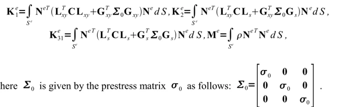
Elementary matrices of equation (7) are given by: K1 e =
∫
Se NeTLxy T C LxyGxy T 0GxyN e d S , K2 e =∫
Se NeTLxy T C LsGxy T 0GsN e d S , K31 e =∫
Se Ne TLs T C LsGs T 0GsN e d S ,Me=∫
Se Ne TNed S , (8)where 0 is given by the prestress matrix 0 as follows: 0=
[
0 0 0
0 0 0
0 0 0
]
.
The resolution of equation (8) allows to determine the modes of propagation. For fixed , the eigen-problem is quadratic in k . For a given real wave number k, we obtain a linear eigen-problem in
2 .
Note that the elastic wave propagation is determined in the prestressed geometry. This static state is computed using a helical homogenization. This technique based on asymptotic expansion reduces the problem to a 2D problem in the cross-section. The static model was validated for helical springs by comparing its results with those of the analytical model of Ancker et al. (1958). For seven wire strands, this model has been validated by comparing its results with those of a 3D finite element model developed by Ghoreishi et al. (2007).
3 Dispersion analysis of a seven-wire strand
The material is assumed to be isotropic, with no material damping. For a steel wire, a typical value of 0.30 will be chosen for the Poisson coefficient. We consider waveguides with a circular cross-section of radius a. The adimensionalized angular frequency is given by a/cs , cs denoting the shear
velocity. Six-node triangles meshes will be used. FE computations are held at fixed real wavenumbers
k.
For helical springs, the SAFE model is validated by comparing its results with the model based on the Timoshenko beam approximation. This reference model was developed in the work of Frikha et al. (2010). In this paper, only the results of a seven-wire strand are presented.
A seven wire strand is made of a straight core of radius a and one layer of helical wires. Rh is the helix
radius. In this section, Rh is assumed equal to 1.967a with an angle of 7.9 ° ( =0,=0.0705 ). The
material properties are as follows: E=2.17e11 Pa, =0.28 , =7800 kg /m3 .
Stick contact conditions are assumed for simplicity (no slip, no separation and no friction are considered). The mesh of the section of the strand is presented in Figure 2. Figure 3-left shows the dispersion curves of a non-prestressed seven wire strand (in black) and of its central wire (in grey) for the adimensional frequency range [0;2]. Due to a strong inter-wire coupling, one observes a far more complex behaviour than for single wires. The most striking phenomenon is the cut-off of the fastest mode “notch frequency” (compressional-like L(0,1) mode) around a / cs=0.35 , corresponding to
83kHz as experimentally observed by Kwun et al.(1998) for a nominal diameter of strand equal to 12.7 mm. The same phenomenon is observed experimentally in the work of Laguerre et al. (2002 b) with a frequency around 68kHz for a radius of the central wire equal to 2.7 mm.
As the axial load increases, this notch frequency shifts to higher frequencies (Figure 3-right). Taking into account the prestress, the deformation of the geometry and the contact without interpenetration between wires, this frequency is located in the vicinity of a / cs=0.443 under 60% of the Ultimate
Tensile Strength load. This frequency corresponds to 105kHz for a nominal diameter of strand equal to 12.7 mm and 86kHz for a radius of the central wire equal to 2.7 mm. This shift of the notch frequency is in agreement with the experimental results of Kwun et al.(1998) and Laguerre et al. (2002 b). This phenomenon is due to the contact between the central and the peripheral wires.
Figure 3: Dispersion curves of non-prestressed strand (left) and a prestressed strand with 60% of the Ultimate Tensile Strength (right).
4 Conclusion
In this paper, a SAFE method was proposed to analyze the effect of prestressing on the wave propagation in a helical waveguide. The prestressed static state was modeled by a method using helical homogenization. The modeling of this state has been validated by comparison with a 3D FE model proposed in the literature. Dispersion inside a non-prestressed and prestressed typical seven wire strand has then been investigated by assuming stick contact conditions. These dispersion curves were compared with experimental results. For an increasing load, the missing band shifts to higher frequencies. This trend is consistent with results obtained experimentally.
References
Rizzo, P. and L. Di Scalea (2004), “Wave propagation in multi-wire strands by wavelet-based laser ultrasound,”
Laguerre, L., J.-C Aime and M. Brissaud (2002 a), “Magnetostrictive pulse-echo device for non-destructive evaluation of cylindrical steel materials using longitudinal guided waves,” Ultrasonics , 39, 503–514.
Kwun, H., K.A. Bartels, J.J. Hanley (1998), “Effects of tensile loading on the properties of elastic-wave propagation in a strand ,” J. Acoust. Soc. Am. , 103, 3370–3375.
Laguerre, L., M. Brissaud and J.-C. Aime (2002 b), “ Dispositif de réflectométrie ultrasonore basse fréquence à base de transducteurs magnétoélastiques pour l'évaluation non destructive des barres et câbles d'acier ,” Bulletin des Laboratoires
des Ponts et Chaussées, 239, 07–27.
Treyssède, F. (2007), “ Numerical investigation of elastic modes of propagation in helical waveguides ,” J. Acoust. Soc. Am., 121, 3398–3408.
Treyssède, F. (2008), “ Elastic waves in helical waveguides ,” Wave Motion , 45, 457–470.
Gavric, L. (1995), “ Computation of propagative waves in free rail using a finite element technique ,” Journal of Sound and
Vibration, 185, 531–543.
Hayashi, T., W.-J. Song and J.L. Rose (2003), “ Guided wave dispersion curves for a bar with an arbitrary cross-section, a rod and rail example ,” Ultrasonics, 175, 175–183.
Damljanovic, V. and R.L. Weaver (2004), “ Propagating and evanescent elastic waves in cylindrical waveguides of arbitrary cross-section ,” J. Acoust. Soc. Am., 115, 1572–1581.
Demma, A., P. Cawley and M. Lowe (2005), “ The effect of bends on the propagation of guided waves in pipes,” Journal of
Pressure Vessel Technology, 127, 328–335.
Onipede, O. and S.B. Dong (1996), “ Propagating waves and end modes in pretwisted beams,” Journal of Sound and
Vibration, 195, 313–330.
Treyssède, F. and L. Laguerre (2010), “ Investigation of elastic modes propagating in multi-wire helical waveguides,”
Journal of Sound and Vibration, 329 (10), 1702–1716.
Bathe, K. J. (1996), Finite Element Procedures, Prentice Hall, Englewood Cliffs, New Jersey 07632.
Ancker, C.J. and J.N. Goodier J.N. (1958), “ Pitch and curvature corrections for helical springs,” Journal of Applied
Mechanics, 466-470.
Ghoreishi, R.S., T. Messager and P. Cartraud (2007), “ Validity and limitations of linear analytical models for steel wire strands under axial loading, using a 3D FE model,” International Journal of Mechanical Sciences 49, 1251-1261.
Frikha, A., F. Treyssède and P. Cartraud (2010), “ Effect of axial load on the propagation of elastic waves in helical beams,” Wave Motion, In press.