HAL Id: hal-01006970
https://hal.archives-ouvertes.fr/hal-01006970
Submitted on 13 Dec 2017
HAL is a multi-disciplinary open access
archive for the deposit and dissemination of
sci-entific research documents, whether they are
pub-lished or not. The documents may come from
teaching and research institutions in France or
abroad, or from public or private research centers.
L’archive ouverte pluridisciplinaire HAL, est
destinée au dépôt et à la diffusion de documents
scientifiques de niveau recherche, publiés ou non,
émanant des établissements d’enseignement et de
recherche français ou étrangers, des laboratoires
publics ou privés.
Influence of fibre volume fraction on mode II
interlaminar fracture toughness of glass/epoxy using the
4ENF specimen
Peter Davies, Pascal Casari, L. A. Carlsson
To cite this version:
Peter Davies, Pascal Casari, L. A. Carlsson. Influence of fibre volume fraction on mode II interlaminar
fracture toughness of glass/epoxy using the 4ENF specimen. Composites Science and Technology,
Elsevier, 2005, 65 (2), pp.295-300. �10.1016/j.compscitech.2004.07.014�. �hal-01006970�
Influence of fibre volume fraction on mode II interlaminar
fracture toughness of glass/epoxy using the 4ENF specimen
P. Davies
a,*, P. Casari
b, L.A. Carlsson
caMaterials and Structures group, IFREMER Brest Centre, BP70, 29280 Plouzane, France bInstitut de Recherche en Ge´nie Civil et Me´canique, University of Nantes, France cDepartment of Mechanical Engineering, Florida Atlantic University, Boca Raton, FL, USA
Glass reinforced composites are used in many structural applications. Their fibre content can vary considerably according to the manufacturing route, typically from 30% to 70% by volume. This paper presents results from an experimental study of the influence of fibre volume fraction on the mode II interlaminar fracture toughness, GIIc, using the 4ENF (four point end notched flexure) spec-imen. Results show that GIIcincreases with decreasing fibre content. This effect is caused by plastic deformation energy dissipation in the thicker resin-rich interlaminar layer in lower fibre content composites.
Keyword: Fracture testing
1. Introduction
Despite efforts to develop composites with through-thickness reinforcements most composites currently in service contain only two-dimensional (in-plane) rein-forcement. Delamination fracture remains an important failure mode in such composites. The development of standardised test methods to characterise the resistance to interlaminar crack propagation, is essential for two main reasons. First, such tests offer the possibility to compare existing and new materials on the same basis. Second, models for prediction of damage development and damage tolerance are becoming increasingly accessi-ble to designers of composite structures, and such mod-els require reliable input data. While an international standard test method now exists for the mode I interla-minar fracture testing of composite materials (ISO
15024) it has proved more difficult to reach agreement for mode II (shear). An obstacle to the most widely-used test, the end notch flexure (ENF) specimen, is that crack propagation is inherently unstable [1–3]. An alternative mode II configuration, shown in Fig. 1, was proposed by Martin and Davidson [4], called the 4ENF (four point end notched flexure) test. This test is potentially very attractive, as the geometry encourages stable crack propagation so that an experimental compliance calibra-tion can be applied for data reduccalibra-tion of the fracture toughness, and a mode II resistance curve may be estab-lished. The 4ENF test employs a four-point flexure rig allowing rotation of the upper loading points. A draft mode II 4ENF test protocol [5] was prepared in 1998 for an international round robin exercise [6], but fric-tional effects have retarded its acceptance as a standard test [7].
Apart from the studies described above, very little work has been published on the 4ENF specimen to date, and most of the published work has involved carbon fi-bre reinforced epoxy composites[8]. Carbon composites
* Corresponding author. Tel.: +33 2 9822 4777; fax: +33 12 9822
4535.
are primarily used for high performance applications based on prepreg, and fibre contents are usually close to 60% by volume. There is also considerable interest in obtaining valid mode II fracture toughness values for more flexible composites. Glass reinforced compos-ites are manufactured using a wide range of methods, including hand lay-up, resin infusion and filament wind-ing and these processes result in widely different fibre contents, from 30% to 70%. It is therefore important to determine the influence of glass fibre content on the mode II interlaminar fracture toughness.
Fibre content has been shown to have a significant ef-fect on mode I delamination toughness. For example Hunston et al.[9]showed much higher GIc values for a composite which was resin rich than for the same mate-rial with a lower resin content. Similarly, recent tests using the edge cracked torsion (ECT) specimen show a strong influence of fibre content on the mode III fracture toughness[10].
In this paper, we will examine the mode II fracture toughness of glass fibre composites over a large range of fibre contents using the 4ENF test. The fracture sur-faces of the specimens will be analyzed in optical and scanning electron microscopes (SEMs) to examine the microscopic mechanisms responsible for the macro-scopic toughness.
2. Experimental 2.1. Materials
The material studied here is a quasi-unidirectional glass/epoxy composite. This consists of 300 g/m2layers
of E-glass fibres impregnated by hand lay-up with an epoxy resin (HY5052), then compression moulded be-tween steel plates. An 8 lm thick polypropylene film, was inserted at mid-thickness during fabrication to act as a starter crack. The reinforcement is described as qua-si-unidirectional because there is a small amount (1 g/m2) of 90° polyester fibres which maintain the cohe-sion of the unidirectional glass fibres and facilitate han-dling during lay-up. The epoxy is a room temperature cure system but a post-cure (5 h at 90 °C) was applied to stabilise the matrix properties.
Seven glass/epoxy panels were produced. The panels contained 20, 26, 30, 36 and 40 plies. Specimen thickness was varied by placing different thickness metallic spacer shims to fix the distance between the steel plates in the press. Large ranges of specimen thicknesses and fibre volume fractions were achieved in this manner. Fibre contents were determined on samples cut from each individual 4ENF test specimen, by resin burn-off at 500°C for 24 h and weighing. A range of fibre volume fractions from 42% to 65% was achieved. The number of plies, thicknesses and fibre volume fractions of these composites are presented in Table 1. Notice also that specimen thickness and fibre volume fraction were de-signed to be uncorrelated to minimize possible thickness influence on the results. The glass transition temperature of the matrix, Tgwas determined by differential scanning calorimetry (DSC) on two samples from each panel (TAI modulated DSC 2920, heating rate 5 °C/min). Tg values varied in a narrow range (71–78 °C) for all panels.
2.2. Test fixtures and procedures
Short beam shear tests were performed on three spec-imens cut from each panel, according to ASTM D2344 with a ratio of span to thickness of 5, at a cross head rate of 5 mm/min. These tests were intended to check panel quality.
The mode II test fixture consists of an upper loading part with a central roller 40 mm above the two loading points, (distance d)Fig. 1. This distance is less than the maximum value (50 mm) according to the draft 4ENF protocol [5]. The specimen is supported at two points
Fig. 1. Mode II 4ENF loading fixture, dimensions in mm.
Table 1
Glass/epoxy specimens
Number of layers Thickness (mm) Fibre content (Vf%)
20 3.7 (0.1) 65 (2) 26 4.6 (0.1) 65 (2) 26 4.9 (0.1) 62(1) 26 6.9 (0.1) 42 (2) 30 6.7 (0.2) 52 (2) 36 7.0 (0.2) 59 (2) 40 7.7 (0.2) 59 (1) Mean values (SD).
and the initial crack length (a0) is 35 mm measured from the left outer loading point.
All tests were performed at displacement rate of 1 mm/min, on a test frame with a 10 kN capacity load cell. The machine crosshead displacement transducer was used to record upper loading point displacements, while crack length measurements were made visually. In addition, two digital cameras were set up to view the edges of the specimen to record the global displace-ment field of the specimen and follow crack propaga-tion. Fig. 2 is a photograph of a deformed specimen which shows the asymmetric displacement of the speci-men. The cameras allowed non-contact measurements of deflections with a resolution of 0.2 mm, and crack lengths with a resolution of 0.1 mm, and were used to check the displacement transducer and visual crack length measurements. For some of the glass/epoxy com-posites, which are transparent, a third digital camera was also employed, viewing the top surface of the spec-imen to detect the crack advance with back lighting. This indicated that the crack front was straight,Fig. 3, so measurements on specimen edges were considered to be reliable.
Before each test an initial compliance calibration was performed (measuring compliance over a range of crack lengths), by sliding the specimen along the fixture, to vary the crack length in 5 mm steps over the range a0= 20–45 mm. Load–unload cycles were performed in the elastic range at each crack length. Then each spec-imen was loaded once to propagate a short mode II crack from the starter film, unloaded and reloaded until the crack propagated to the loading roller. After this crack propagation, a second compliance calibration was made over the range of crack lengths from 35 to 80 mm.
2.3. Data reduction for GIIc
The mode II interlaminar fracture toughness, GIIc, was reduced from 4ENF test data using an experimental compliance calibration method with the compliance expression[5]
C¼ C0þ ma; ð1Þ
where C is the specimen compliance, and a is the crack length. The fracture toughness, GIIC, is
GIIc¼P 2 cm
2B ; ð2Þ
where Pcis the critical load, m is the slope of the com-pliance versus crack length plot, and B is the specimen width. GIIcwas determined for each crack length using the onset of non-linearity on the load–displacement plot, and a compliance versus crack length plot determined for each specimen.Fig. 4shows an example of a compli-ance calibration plot established from measurements be-fore crack propagation (sliding) and during the fracture test (propagation). The slopes (m) measured using both methods are indicated inFig. 4. The small difference in slope may be due to a difference in crack length meas-urement as the true position of the crack tip after crack propagation was obscured by the damage zone formed near the front. All GIIc values reported herein were determined using the slope (m) measured during propagation.
Fig. 2. Example of image of deformed specimen under load.
Fig. 3. View through specimen showing straight crack front.
C (Propagation) =0.0717a + 1.43 R2 = 0.9954 C (sliding) = 0.0663a + 1.59 R2 = 0.9856 0 0 20 40 60 80 2 4 6 8 Crack length,mm Compliance, µ m/N Propagation Specimen sliding Propagation Sliding
Fig. 4. Compliance calibrations curves determined on the same specimen before the fracture test and during propagation.
3. Results and discussion
Short-beam shear strength data are shown inFig. 5. The interlaminar shear strength does not depend on fi-bre volume fraction, a consequence of its dependence on the fibre/matrix shear strength.
Seventeen mode II specimens cut from the panels pre-sented in Table 1 were tested. Examples of load–dis-placement plots from the first tests, performed on panels with 20 and 30 plies, are shown in Fig. 6. Two plots are given for each specimen, one corresponding to the first loading to generate a short shear crack from the insert film, and the second loading to propagate the crack. These plots indicate essentially linear behaviour up to crack initiation. For each specimen two initiation values were determined, one from the initial starter film and one from the mode II precrack. Then 7–10 propaga-tion values were recorded. Fig. 7 shows examples of mode II interlaminar toughness versus crack length curves (resistance curves) at fibre volume fractions of 52% and 62%. For each composite the toughness in-creases somewhat during crack propagation. The varia-tions are typical for hand laid up composites, but may also arise from the periodic 90° polyester fibres.
Fracture toughnesses determined for all test speci-mens are plotted versus fibre content in Figs. 8 and 9. The toughness decreases quite substantially with increasing fibre content. Furthermore, initiation values determined by propagation from shear precracks exceed those determined by propagation direction from the in-sert film,Fig. 8. This increase could be due to accumu-lated plasticity effects for the shear precracked specimens. At high fibre contents the toughness levels off to assume a plateau level apparently dominated by fiber/matrix interfacial adhesion rather than matrix plasticity at the closed-packed fibre configurations
ap-0 10 20 30 40 50 60 40 45 50 55 60 65 70
Fibre volume fraction, %
ILSS (MPa)
Fig. 5. Interlaminar shear strength values. Error bars show minimum and maximum values.
0 1 2 3 4 2 0 Displacement, mm Force, kN 30 plies, Vf=52% 20 plies, Vf=65% 6
Fig. 6. Load–displacement plots for two specimens with different fibre contents and thicknesses. First loading from insert film and reloading from mode II pre-crack.
0 1 2 3 40 50 60 70 80 Crack length (mm) GIIc (kJ/m ² ) 30 ply, Vf = 52% 20 ply, Vf = 65%
Fig. 7. GIIcresistance curves for the specimens inFig. 6.
0 1 2 3 4 35 40 45 50 55 60 65 70 Fibre content, % GIIc (initiation NL), kJ/m² Insert film Shear precrack Polynomial (Insert film) Polynomial (Shear precrack)
Fig. 8. Initiation values of GIIcversus fibre volume fraction.
0 1 2 3 4 35 40 45 50 55 60 65 70 Fibre content, % GIIc (propagation), kJ/m ²
proached at these high fibre volume fractions. Table 2
summarises the values for the low and high fibre con-tents. It is clearly observed that there is a strong effect of fibre volume fraction on the initiation and propaga-tion toughnesses.
There are a number of possible explanations for the large influence of fibre volume fraction on the mode II delamination toughness. First, it may simply be that the extent of cure of the resin in the panels with the low-est fibre contents differs from that in those at higher fibre contents. The measured glass transition temperatures re-ported earlier, however, indicate that this is not the case. Another possibility is that the specimen stiffness
(thick-ness) affects measured toughness but no correlation was noted. For example, the specimens with the lowest fibre contents were not the thickest ones.
A more plausible reason for the high toughness of the low fibre content specimens is crack tip plasticity effects
[9]. To examine this factor in more detail, the specimen edges near the crack front, and fracture surfaces were examined in a SEM. Starter film regions of polished edges of specimens were examined in the SEM detailing the film insert region where crack propagation begins.
Fig. 10shows the edge views of the insert region for ver-tically arranged low and high fibre volume fraction spec-imens. For the lowest fibre content composites the resin rich layer extends about 50 lm on both sides of the in-sert film, see Fig. 10(a). Resin rich regions occur at all the regions between reinforcement layers. At high fibre contents the insert film is closely surrounded by fibres and the resin rich region is less than 10 lm thick, see
Fig. 10(b). The thickness of this resin layer is a striking difference between the low and high fibre content com-posites (Vf= 40–45% and Vf= 50–68%, respectively).
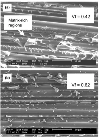
The fracture surfaces near the insert region, Fig. 11, reveal that the presence of the matrix rich region in the low fibre volume fraction composite, Fig. 11(a), al-lows the development of a damage zone involving plas-tically deformed and micro-cracked matrix material near the tip of the insert film. This observation could explain the more extensive energy dissipation in this
Fig. 10. Scanning electron micrographs of specimen edge in the starter film region: (a) Vf= 42%; (b) Vf= 62%.
Table 2
Initiation and propagation values of mode II toughness Range of Vf Initiation from insert
film (kJ/m2) Propagation (kJ/m2) Mean (SD) Number of values Mean (SD) Number of values 40–45% 2.13 (0.07) 3 3.04 (0.45) 24 >55% 0.98 (0.18) 11 1.64 (0.35) 96
Fig. 11. Scanning electron micrographs of fracture surfaces, initiation region: (a) Vf= 42%; (b) Vf= 62%.
composite. No such matrix region is observed in the high volume fraction composite, Fig. 11(b). Closer examination of the fracture surfaces in the propagation region, Fig. 12, reveals a large amount of shear micro-cracks that extend through the resin rich region in the low fibre content specimen,Fig. 12(a). For the higher fi-bre content specimen,Fig. 12(b), shear cracks also initi-ate but cannot develop as they impinge on the fibre/ matrix interface much sooner and the delamination crack becomes trapped in a narrow region around the ply interface. This results in much less matrix deforma-tion and clean fibres seen on the fracture surfaces. It is interesting to note that Chai[11] conducted shear frac-ture tests on adhesively bonded metal specimens and found a strong increase in mode II toughness as the adhesive layer thickness was increased. Similarly, Carls-son[12]showed a strong effect of resin film thickness on delamination toughness of interleaved carbon fibre composites.
4. Conclusions
This paper shows that the 4ENF specimen is well-suited to measuring mode II delamination toughness in glass/epoxy composites, providing full resistance curves. Initiation values fall significantly below the propagation values and the minimum initiation values are measured
from propagation directly from the insert film as op-posed to propagation from a short mode II precrack. A study of the influence of fibre content on the delami-nation toughness, GIIC, revealed that the toughness is high for resin rich composites and this is attributed to the importance of a thick interlaminar resin rich layer in the low fibre content composites that allows plastic deformation to extend over a larger volume than in the high fibre content composites.
Acknowledgements
The contributions to the experimental programme at IFREMER of Henri Loaec and Thomas Kimpflin are gratefully acknowledged. Thanks are due to Mrs. Melissa Morris for her help with the typing of the final revisions of this manuscript.
References
[1] Davies P, Blackman BRK, Brunner AJ. Mode II delamination. In: Moore DR, Pavan A, Williams JG, editors. Fracture testing methods for polymers, adhesives and composites. ESIS Publica-tion 28, Elsevier; 2001. p. 307–34.
[2] Barrett JD, Foschi RO. Mode II stress intensity factors for cracked wood beams. Eng Fract Mech 1977;9:371.
[3] Russell AJ, Street KN. Factors affecting the interlaminar fracture energy of graphite/epoxy laminates. In: Hayashi T, Kawata K, Umekawa S, editors. Proceedings of the ICCM-IV, Tokyo, 1982, 279.
[4] Martin RH, Davidson B. Mode II fracture toughness evaluation using a four point bend end notched flexure test. In: Proceedings of the 4th international deformation and fracture of composites conference (DFC4). London: Published by Institute of Materials; March 1997. p. 243–52.
[5] Martin RH. Protocol for the determination of the mode II delamination resistance of unidirectional fiber reinforced polymer matrix composites using the four point bend end notched flexure (4ENF) specimen, MERL, reference 8-1-98. Protocol used for VAMAS Round robin tests; 1998.
[6] Davies P, Sims GD, Blackman BRK, Brunner AJ, Kageyama K, Hojo M, et al. Comparison of test configurations for determina-tion of mode II interlaminar fracture toughness results from international collaborative test programme. Plast Rubber Com-pos 1999;28(9):432–7.
[7] Kageyama K, Kimpara I, Suzuki T, Ohsawa H, Kanai M, Tsuno H. Effects of test conditions on mode II interlaminar fracture toughness of four-point ENF specimens, Proceedings of the ICCM-12, Paris; July 1999. p. 362.
[8] Schuecker C, Davidson BD. Evaluation of the accuracy of the four point bend edge notched flexure test for mode II delamina-tion toughness determinadelamina-tion. Compos Sci Tech 2000;60:2137–46. [9] Hunston DL, Moulton RJ, Johnston JJ, Bascom WD. Matrix resin effects in composite delamination: mode I fracture aspects. ASTM STP 1987;937:74–94.
[10] Li X, Carlsson LA, Davies P. Influence of fiber volume fraction on mode III interlaminar fracture toughness of glass/epoxy composites. Compos Sci Technol 2004;64(9):1279–86.
[11] Chai H. Shear fracture. Int J Fract 1988;37:137–59.
[12] Carlsson LA. Fracture of laminated composites with interleaves. In: Fracture of composites. In: Armanios EA, editor. Key Eng Mat, vol. 120–121. Trans Tech Publications; 1996. p. 489–520. Fig. 12. Scanning electron micrographs of fracture surfaces,