HAL Id: hal-01709496
https://hal.archives-ouvertes.fr/hal-01709496
Submitted on 15 Feb 2019
HAL is a multi-disciplinary open access
archive for the deposit and dissemination of
sci-entific research documents, whether they are
pub-lished or not. The documents may come from
teaching and research institutions in France or
abroad, or from public or private research centers.
L’archive ouverte pluridisciplinaire HAL, est
destinée au dépôt et à la diffusion de documents
scientifiques de niveau recherche, publiés ou non,
émanant des établissements d’enseignement et de
recherche français ou étrangers, des laboratoires
publics ou privés.
Curing simulation of composites coupled with infrared
heating
Sawsane Nakouzi, J. Pancrace, Fabrice Schmidt, Yannick Le Maoult,
Florentin Berthet
To cite this version:
Sawsane Nakouzi, J. Pancrace, Fabrice Schmidt, Yannick Le Maoult, Florentin Berthet. Curing
simulation of composites coupled with infrared heating. International Journal of Material Forming,
Springer Verlag, 2010, 3 (1), pp.587-590. �10.1007/s12289-010-0838-5�. �hal-01709496�
____________________
* F.M. Schmidt : [email protected]
CURING SIMULATION OF COMPOSITES COUPLED WITH INFRARED
HEATING
S. Nakouzi, J. Pancrace, F.M. Schmidt*, Y. Le Maoult, F. Berthet
Université de Toulouse ; INSA, UPS, Mines Albi, ISAE ; ICA (Institut Clément Ader); Campus
Jarlard, F-81013 Albi cedex 09, France
Ecole des Mines Albi, Campus Jarlard, F-81013 Albi, France
ABSTRACT: Because of higher specific strength and stiffness, low weight, and good resistance to corrosion, the use of
composite materials in aerospace structures has increased. Aircraft industry has recently begun to investigate Liquid Composites Molding techniques (LCM) through research programs because of its ability to produce large parts at a low cost. In this paper, we have not addressed the filling step during which the resin flows through fibrous media, but we investigate the numerical simulation of curing reinforced RTM-6 by infrared heating. Finite element based program COMSOL Multiphysics™ has been used to simulate the curing process. Thermochemical model has been implemented in order to compute reaction rate as a function of reaction temperature and degree of conversion using a cure kinetic model .
KEYWORDS: composite, infrared heating, degree of curing, epoxy resin, carbon fibers, numerical modeling.
1 INTRODUCTION
Using thermal radiation to cure the composite is more efficient and effective than standard thermal energy sources. Thermal radiation was successfully used to produce a high quality polymer matrix in less time [1].We assumed the infrared interaction with the composite is a surfacic heat flux on the top surface [1,2]. The energy equation was coupled with the exothermic heat released during the curing process in order to predict the composite temperature as a function of time and degree of cure.
2 LIQUID RESIN INFUSION (LRI)
Liquid infusion process was used is this study to implement the composite; the mould used is a single-sided mould which is sealed with a vacuum bag and the recovery surface is transparent to the infrared radiation. In the LRI, the infusion and the curing process take place at ambient pressure.
Figure 1: Schematic presentation of the LRI process.
3 INFRARED INTERACTION
Because the graphite fibers embedded in the epoxy resin are very strong infrared absorbers over broad spectral
ranges at all wavelengths, the composite has strong absorption bands in some portions of the spectrum as a first approach; we have neglected epoxy absorption in this paper [1, 2, 3, 4].
3.1 BOUNDARY CONDITIONS
The composite is assumed to be a block with (20x10x1mm) dimensions. It is composed of the superposition of a sequence of carbon plies embedded in an epoxy matrix [5].
Figure 2: Schematic presentation of the composite face
to the infrared emitters.
The infrared radiation is absorbed by the carbon ply present in the top surface of the composite. This incident infrared radiation on the top surface was taken as a boundary condition in COMSOL MultiphysicsTM .There is also natural heat convection between this surface and the air present in the oven. The other boundaries are assumed to be adiabatic: the bottom is in contact with a mould and there is no heat exchange between the mould and the composite. The frame of the composite is so thin in comparison to the surface, that we can ignore the heat exchange all around its contour.
Mould Fibers
Porous net Recovery Felt
Rubber Extraction tissue Air aspiration Resin t IR heaters d l w Composite
4 ENERGY EQUATION
The composite transient temperature can be evaluated by the Fourier’s modal equation assuming an instantaneous equilibrium temperature between the resin and the fibers at each time: [6, 7]
!"#$,"&'&(= ∇(,"∇-) + 01!123&4&( (1)
Where 23= ultimate heat of reaction, 5 = degree of
curing, and the !" = density, #$,"= heat capacity, ,"=
thermal conductivity of the composite are expressed using the rule of mixture:[8, 9, 10]
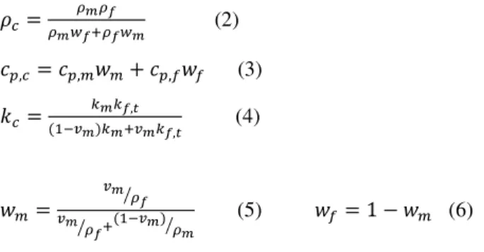
!"= BCBD BCEDFBDEC (2) #$," = #$,1G1+ #$,HGH (3) ," = ICID,J (KLMC)ICFMCID,J (4) G1= MCB D N MC BD N F(KLMC)NBC (5) GH = 1 − G1 (6)
Where ,H,(= transverse thermal conductivity of the
fibers, G = weight fraction, 0 = volume fraction, the subscript Q stands for the fibers, and R for the matrix. The system of equations described above can be solved at each time step in order to calculate the distributions of temperature and degree of curing and their evolution with time.
5 KINETIC MODELING
5.1 GLASS TRANSITION TEMPERATURE
The glass transition temperature is modelled using the DiBenedetto equation:[8]
-S= -ST+
('UVL'UW)X4 KL(KLX)4 (7)
Where -ST and -SY = glass transition temperature of
un-reacted and full-un-reacted resin, Z = material constant. These values were deduced from the literature [7].
5.2 KINETIC MODEL
Kamal and Sourour [6] have shown that the following model adequately describes the cure kinetics of an epoxy resin:
[4
[( = (,K+ ,\5
1)(1 − 5)] (8)
,^= _^exp (−c'ab) d = 1, 2 (9)
Where ,K and ,\ = rate constants with an Arrhenius
type of dependence with temperature and R and f = catalytic constants.
Although the model of Kamal and Sourour [6] contains several essential features, it ignores the influence of the glass transition temperature -S on the diffusion of the
macromolecules.
This model [6]
has
been extended in order to reflect the effect of vitrification in the kinetic model of resin transfer molding. This model was also used by [7][4 [( = ( IgIh IgFIh+ IiIh IiFIh5 1)(1 − 5)] (10) ,j= ,kexp (−lH) (11) Q = QT+ m(- − -S) [10] (12)
Where ,j = diffusion factor, ,k = diffusion rate
constant, n = constant having the order of one, -S = glass
transition temperature, Q = free volume fraction of the polymer[11], QT = free volume fraction for a temperature
equal to -S, m = thermal expansion coefficient for a
temperature above -S.
For an amorphous polymer [10] which is the case of our composite, QT= 0,025 and m = 0,00048.
5.3 KINETIC PARAMETERS
Kinetic parameters of RTM6 resin are calculated using linear regression algorithms by fitting model equations
[4
[( = Q(5, -) with the Differential Scanning Calorimeter
experimental data. These experimental DSC data were scanned isothermally for different temperatures: 140, 160, 170 and 180°C.
In the DSC, the rate of heat generation st/sv is recorded with time. As
2
3 is constant for a given curing process, [7, 8, 12] the rate of the degree of curing is calculated by: [4 [( = K 2w [x [( (13)The degree of curing is obtained by integrating the DSC data and normalizing with
2
w.
5.4 FITTED KINETIC PARAMETERS
The figure 3 below shows the temperature dependence of factors y1 and y2 [11]which exhibits an Arrhenius type of temperature dependence.
The estimated kinetics parameters from the fitting curves used in our simulations are listed in table 1 below.
Table 1: Estimated parameters
Parameter _K [RdfLK] 4.5E6 zK [{/R|}] 74.69E4 _\ [RdfLK] 1.3E6 z\ [{/R|}] 58.37E4 _k [RdfLK] 85.2E28 zk [{/R|}] 2.16E5 R [-] 1.23 f [-] 1.36 n [-] 0.227 23 [J/kg] 4.30E5 R [J/(mol-K)] 8.314
6 NUMERICAL EXAMPLE
The carbon fibers embedded in the epoxy are very strong absorbers in that they absorb infrared energy and convert this energy to heat the epoxy matrix surrounding the carbon fibers. Thermal radiative boundary conditions are imposed on the top surface of the composite and the curing temperature is controlled through the infrared emitters in order to optimize a uniform surface heat flux. The emitters used in our project are halogen lamps given from TOSHIBA LIGHTING; their infrared emission is in the short and medium wavelength.
Until now, the composite properties were taken from literature [1, 8]. Others are assumed to be constants in order to run some initial simulations of a curing process of RTM6 as a matrix combined with a fibrous reinforcement in the form of carbon plies.
In this numerical example, a high heat flux of 1600 •/ R² was provided for the first 6 minutes in order to
initiate and accelerate resin curing, and for the rest of time, the surface heat flux taken was 1200 •/R². These
heat flux values were imposed in a way to cure the composite with less time and do not exceed 220°C in temperature (the degradation temperature of the matrix). We based our studies on an experimental anterior work in the laboratory; where we found that the composite’s curing process occurred faster than other heating processes.
6.1 NUMERICAL RESULTS
Using COMSOL Multiphysics, the energy equation was coupled with the exothermic reaction in order to predict the temperature distribution in the composite and the degree of cure.
The figures 4 and 5 below show the temperature and the degree of curing respectively evolution with time at the center of the composite.
Figure 4: Temperature evolution versus time at the
center of the composite (0.5mm thickness)
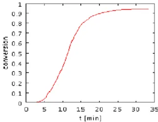
Figure 5: Degree of cure evolution versus time at the
center of the composite (0.5mm thickness)
The figures 6 and 7 below show the temperature and degree of cure respectively evolution with time and thickness of the composite.
Figure 6: Temperature evolution versus time and
Figure 7: Degree of cure evolution versus time and
thickness
These numerical simulations correspond to a 1mm thickness composite; there is no important variation of the temperature or degree of curing with the thickness. From these simulations, we can deduce that the curing of the composite is accomplished in less time than the others modes of heating.
In the future work, we need to validate our numerical simulations with experimental infrared curing.
7 CONCLUSIONS
The curing model of resin is investigated in this study. A modification of the Kamal-Sourour curing model is given to account for the diffusion effect. Kinetic parameters of the curing model based on DSC Experiments were estimated using optimization algorithms. The thermal-kinetic model has been developed in COMSOL Multiphysics to simulate the curing process of pure resin with assumed material properties. In-lab software developed to predict the infrared heat flux on the top surface of the composite will be coupled with COMSOL in order to simulate the whole infrared curing process of the composite.
ACKNOWLEDGEMENT
The authors would like to thank Mr. Goyot D. for his support. Grateful acknowledgement to TOSHIBA LIGHTING for their financial support and their attention to this work.
REFERENCES
[1] Chern B.C, Moon T. J., Howell J. R.: On-Line Processing of Unidirectional Fiber Composites Using Radiative Heating: I. Model. Journal of Composite Materials , 36,1905,2002
[2] Chern B.C, Moon T. J., Howell J. R.: On-Line Processing of Unidirectional Fiber Composites Using Radiative Heating: II. Radiative Properties, Experimental Validation and Process Parameter Selection. Journal of Composite Materials , 36,
1935, 2002
[3] Kim J., Moon T. J., Howell J. R.: Transient Thermal Modeling of In-Situ Curing During Tape Winding of Composite Cylinders. Journal of Heat Transfer,
125-137, 2003
[4] Chern B.C, Moon T. J., Howell J. R.: Thermal Analysis of In-Situ Curing for Thermoset, Hoop-Wound Structures Using Infrared Heating: Part II – Dependent Scattering Effect. Journal of Heat Transfer, 117-681, 1995
[5] Cunningham E., Monaghan P. F. and Brogan M. T.: Prediction of the temperature profile with a composit sheets during pre-heating. Composite part A. 51-61,
1998.
[6] Bailleul J. L., Guyonvarch G., Garnier B., Jarny Y., and Delaunay D.: Identification des propriétés thermiques de composites fibres de verre / résines thermodurcissables Application a l’optimisation des procédés de moulage. Revue Générale Thermique,
36, 65-77, 1996
[7] Ruiz E. and Trochu F.: Thermomechanical Properties during Cure of Glass-Polyester RTM Composites: Elastic and Viscoelastic Modeling.
Journal of Composite Materials, 39; 881, 2005
[8] Ruiz E. and Trochu F.: Multi-criteria thermal optimization in liquid composite molding to reduce processing stresses and cycle time. Composites: Part A 37, 913-924,2006
[9] Balvers J.M., Bersee H.E.N., Beukers A., K.M.B. Jansen: Determination of Cure Dependent Properties for Curing Simulation of Thick-Walled Composites. In: 49th AIAA/ASME/ASCE/AHS/ASC Structures, Structural Dynamics, and Materials Conference, 2008.
[10] Nguyen T. M. H. : Systèmes époxy-amines incluant un catalyseur externe phénolique : Cinétique de réticulation- vieillissement hydrolytique, 2007. [11] I. Elsawi, P. Olivier, P. Demont, C. Laurent, A.
Peigney: Rheological and kinetic behavior of double-walled carbon nanotubes filled epoxy resin. JNC 16 Toulouse, 2009.