HAL Id: hal-00739857
https://hal.archives-ouvertes.fr/hal-00739857
Submitted on 9 Oct 2012
HAL is a multi-disciplinary open access
archive for the deposit and dissemination of
sci-entific research documents, whether they are
pub-lished or not. The documents may come from
teaching and research institutions in France or
abroad, or from public or private research centers.
L’archive ouverte pluridisciplinaire HAL, est
destinée au dépôt et à la diffusion de documents
scientifiques de niveau recherche, publiés ou non,
émanant des établissements d’enseignement et de
recherche français ou étrangers, des laboratoires
publics ou privés.
A UML profile for model-driven design of software
defined radio applications
Mercury Jair Gonzalez Pina
To cite this version:
Mercury Jair Gonzalez Pina. A UML profile for model-driven design of software defined radio
appli-cations. (RTSS-SOMRES 2011), Nov 2011, Vienna, Austria. pp.1-6. �hal-00739857�
A UML profile for model-driven design of software
defined radio applications
Jair Gonzalez
Telecom ParisTech, LTCI CNRS
2229 Route des Cretes, B.P. 193, 06904 Sophia-Antipolis Cedex, France Email: [email protected]
Abstract—Model-driven design (MDD) is considered a very promising approach to cope with complex software applications such as software defined radio (SDR). This paper proposes a MDD approach for SDR applications. Our approach comprises: (1) DiplodocusDF, a domain-specific modelling language for telecommunication applications, which is based on UML. (2) The mechanism to transform DiplodocusDF models into C-language code ready for compilation, and (3) a runtime environment for the generated code. Moreover, the proposed UML profile is supported by Ttool, which is a framework for design exploration and formal verification at model level. We illustrate the potential of our methodology designing a SDR application.
I. INTRODUCTION
Current design methodologies cannot cope efficiently with the high complexity of software defined radio (SDR) applications[1]. SDR applications are extremely complex as they have to conciliate many different opposing fac-tors, for example: high-performance and hard-real-time, inter-operability and safety, etc. Also, novel SDR platforms, such as expressMIMO[2], account for the software complexity, as they are tuned for computation efficiency, in terms of speed and power consumption, but its operation is hard and error-prone. It is compulsory to introduce an automated tool that abstracts the execution platform and allow the domain expert to concentrate only on the pure application matters.
Model driven design (MDD) is considered to be a promising approach to handle the development of complex software sys-tems, [3], [4], [5]. MDD allows describing the applications in the problem-space rather than in the solution-space. In MDD, the problem is described by the designer using an intuitive specific-domain modelling language, and the implementation solution is found automatically by synthesis mechanisms. This releases the designer of having to be a platform and a low-level language expert. This sole abstraction simplifies the design effort and reduces the possibility of implementation errors. MDD also allows for design exploration at model level, therefore the model can be simulated and evaluated without writing a single line of code.
This paper proposes a model driven design methodology for software defined radio (SDR) applications. SDR applications are constructed based on coarse grain operations that are common to most of the existing telecommunications standards. These operations have a set of parameters that configure the behaviour of the operations according to a given standard. SDR
applications coordinate the execution of the course grain op-erations. Data-flow modelling is a good candidate to describe SDR applications as it helps to exhibit the potential parallelism among operators, and thus take profit from multiprocessing platforms such as expressMIMO[2] or others.
This methodology includes the SDR domain-specific mod-elling language DiplodocusDF, and the synthesis mechanisms capable of generating executable code from the DiplodocusDF model description. The proposed domain-specific modelling language is based on UML. It was chosen to use UML due to its robust graphical notation and its flexibility to be extended to cover domain-specific applications. Previous works [4], [5] advocate the potential of UML for embedded MDD, thanks its broad adoption. The synthesis mechanism of our MDD approach translates DiplodocusDF models into C-code, and will also find scheduling and memory allocation solutions. The solutions will consider the characteristics of the target execution platform. Moreover, our methodology is supported by Ttool[6], which is a model-level design exploration tool. Ttool allows fast model simulation and formal verification.
The main contribution of this paper is the definition of DiplodocusDF. This UML profile captures the semantics of the software defined radio domain and allows automatic code gen-eration in an incremental way, from just translation (of detailed DiplodocusDF models into ready-to-compile C-code) to full synthesis (from abstract models into ready-to-compile C-code, including generation of scheduling and memory management solutions). The synthesis aspects of our MDD methodology are part of ongoing research work that will be discussed briefly in this paper.
The rest of the paper is organized as follows: The related work is described in section II. Section III discus with more detail the MDD methodology proposed in this paper. Section IV describes the proposed modelling profile DiplodocusDF. SectionVI elaborates on the runtime environment that supports the execution of the generated applications. A case of study is presented in section V. The future work and conclusions are discussed in section VII.
II. RELATED WORK
Considerable research has been conducted to propose MDD methodologies based on UML. The papers [4] and [5] discuss the potential of UML for model-driven design, in particular for embedded systems. The paper [7] proposes a UML based
methodology for code generation of embedded applications, such as SDR. It describes a series of transformations into intermediate languages and assumes a last transformation into executable code, no details are given on how to take into account the platform aspects of the system. The authors of [8], [9], [10], [11] propose MDD/UML methodologies to generate hardware components of stream systems, without considerations of the software components. The papers [12], [13] propose MDD/UML/MARTE methodologies for embed-ded applications. UML/MARTE itself lacks the notations to describe dataflow applications (such as SDR) in a pure abstract way. The authors of [14] study the possibility to integrate synchronous dataflow models with UML and they propose a dataflow notation based on UML-RT profile. The paper [15] presents an approach to use activity diagrams of UML 2.0 for business dataflow applications. Their proposal is similar to ours in covering flat control-flow and data-flow, as suggested in [16], but their objective is only modelling and no concepts of synthesis are taken into account.
III. PROPOSED DESIGN METHODOLOGY
The proposed design methodology is depicted in figure 1. The processing steps are: (1) Model Capture, (2) Mapping, (3) Simulation and verification, (4) Synthesis, and (5) Compilation and Linking.
Steps (1) and (5) are common in current design flows, but they are done independetly from each other. As it is noted in [3], [5], this separation leads to problems of synchrony between the model and the actual implementation. Also noted in [3], [5], several previous modelling languages failed to be adopted because they were too general, or failed to capture the semantics of the given applications. We defined DiplodocusDF, a UML profile for the domain of telecommunications, de-scribed in more details in section IV.
The steps (2) and (3) have been studied in [17], [18]. They propose profiles and tools for design exploration at model level, aided of model simulation and formal verification. This helps the designer to take informed design choices before implementation. It is important to note that this methodology separates, as suggested in [19], the application model from the execution platform model. The relation between application and platform is established in step (2). This is a very nat-ural approach for Software Defined Radios, where the same application can be executed in different platforms.
Model simulation and formal verification improve the de-sign flow by helping the dede-signer to take better dede-sign choices. But the problem of synchrony is still there, the model will no longer represent the final implementation. Step (4) establishes a link between the model and the implementation by generat-ing automatically the source code that will be compiled and then executed. The DiplodocusDF profile was designed in such a way that it allows for incremental automation of the code generation, from translation to real synthesis. Until now we have results on translation of the model into C-code, this is described in section VI, although we are already working on the synthesis. model Application model Platform description Intermediate Simulation & Verification RunTime Compilation Library of components C−code Applications C−code MP−RTOS executable & Linking Model capture Mapping Synthesis
Fig. 1: Proposed model-driven design methodology.
IV. DIPLODOCUSDF
A key component of a MDD methodology is the domain-specific modelling language (DSML) that captures accurately the semantics of the given application. A DSML should meet certain criteria in order to be really effective. First, it should differentiate the pure application aspects from the implementation choices, i.e. the models should avoid including implementation constraints as it reduces the solution-space. Second, it should be complete in the sense that it captures all the information that is necessary to generate executable code. Other aspects to consider when defining a DSML are: It should be an intuitive language for the domain expert and it should be predictive, that is, it should be evident what the result will be after automatic code generation.
DiplodocusDF is a UML profile specific for SDR applica-tions. It allows the description of the pure application aspects following a declarative data-flow approach. This approach contrasts to the procedural approach (followed by regular UML/MARTE profiles) in that dataflow describes what the so-lution is, contrary to the procedural approach which describes how to find the solution. Procedural approaches lead to models where a component is on charge of controlling the execution of the rest. That controlling component represents in fact schedul-ing design choices, which are unnecessary when modellschedul-ing the pure aspects of a given application. DiplodocusDF describes only data dependencies between process operators, it does not constraints the order of execution of two non-dependent operators. Its is in a high degree similar to Kahn process networks[20], which are appropriate for SDR as it enforces portability, determinism and parallelism [16], but in our case we have memory limitations.
In fact, DiplodocusDF extends the UML profile DIPLODOCUS[18] to cover synchronous dataflow models. DIPLODOCUS is a UML/MARTE compliant profile meant for modelling embedded applications, but it leads to procedural modelling approach. It is convenient to use DIPLODOCUS as starting point because it already allows modelling the applications as a set of independent components that communicate with each other through data-channels.
DiplodocusDF describes a network of dataflow operators interconnected by dataflow links through dataflow ports.
Dataflowis a sequence of pairs made of data-block and clock signalling when the data-block is present. This is similar to the flow concept in [21], although we need a coarser representation of data, in our case data blocks, in their case single data elements.
A. DiplodocusDF notations
DiplodocusDF offers three types of model notations to create SDR models: (1) Dataflow operators (2) Dataflow ports and (3) Dataflow links. They extend, in the same order, the component, port and link concepts of DIPLODOCUS to support the pair (data-block, clock) of synchronous dataflow models.
a) Dataflow ports: are the interface to exchange dataflow between dataflow operators. They support dataflow semantics, i.e. data-block and clock transference. For this they merge two types of ports supported in DIPLODOCUS: channels and events. The channel part models the data-block part of dataflow, while the event part models the clock part. The event signals the presence of a valid data-block in the channel. The channel is configured to be non-blocking read / non-blocking write (NBR / NBW), this allows dynamic data-block size during model simulation, therefore component re-utilization. Each dataflow port can be linked to only one other port. A dataflow operator can have one or more input and output ports.
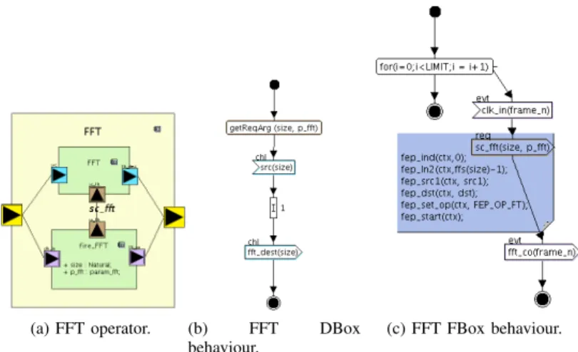
b) Dataflow operators: are composed of two subcom-ponents: DBox and FBox. When fired, the DBox processes the data-blocks. The process involves: reading the operation parameters, reading the data-block from the input dataflow port(s), execute the operation, and sending the resulting data-block though the NBR / NBW output port. The FBox waits for input clock signal, generates the configuration parameters, fires the corresponding DBox, and sends a clock event through the output dataflow port(s). The parameters of execution are sent to the DBox through an internal request port. The behaviour of both sub-components is described using activity diagrams. An example of dataflow operator is depicted in 2a. The FBox is called fire_FFT, it fires the execution of the DBox called FFT through the request signal sc_fft. Figure 2c shows the behaviour of the FBox sub-component, it waits for the clk_in blocking event, then it sends the request signal sc_fft with the parameters size and p_fft, and waits again for the clk_in event. The figure 2b shows the activity diagram of the DBox. It gets the request arguments, then it reads the src channel a block of size elements. Then it models the execution of the operation, which in this example takes 1 time units. Finally it writes the resulting data-block through the fft_dest channel.
there are two types of operators: execution based and router based. The execution operators transform the data-block values while the router operators transform the sequence of the values. For example, a modulus operator will change the values of the input data, while a multiplexer overlapping operator will not change the values but its sequence. This
(a) FFT operator. (b) FFT DBox behaviour.
(c) FFT FBox behaviour.
Fig. 2: Example of dataflow operator.
approach permits defining reusable model operators, that can be instantiated and configured by the user. The router operators also introduce the notion of abstract memory, necessary to store data-blocks that can be re-send later.
c) Dataflow links: are used to stablish the data-block de-pendencies among the dataflow operators through the dataflow ports.
B. DiplodocusDF semantics
DiplodocusDF captures the semantics of software defined radio applications, and also the semantics of the target appli-cation in which the model will be translated.
d) Operators: As said before, SDR application involve the coordination of the execution of coarse grain operations, which are common to most telecommunications standards. Examples of these operations are: Fast-Fourier transformation, interleaving, component-wise product of two vectors, etc. The operations are implemented to be configurable, according to the given telecommunications standard for which the operation is been used.
The model operators are translated to C as coordination functions (CF) which are executed when its input data is avail-able. The attributes of the UML operator model are translated as variables and the activity diagram of the FBox is translated to C-code. For now, we include in the models what we call
code-boxeswhere the designer can write the corresponding C-code that will be embedded inside the coordination function. The figure 2c shows code-box example. The coordination functions involves generating the parameters for the course grain operations and its scheduling for execution.
When targeting multi-processor platforms such as express-MIMO, frequently, data has to be transferred from one mem-ory space to another. That implies extra operations, which are not part of the pure application model. This situation is identified at mapping time, when the designer has to specify in which memory space will be located each port. If two linked ports lay in different memory spaces, a new operator has to be introduced, which implements a data transference between
memory spaces. The input port of the new operator inherits the name and parameters of the original source port, while the output port inherits the name and parameters of the original destination port.
e) Router operators: These operators do not transform the input data but its sequence. The output blocks are created based on the data elements of the received blocks. The data is the same but is output in different order. For example: Data overlapping, data repetition, data multiplexing, data demulti-plexing, etc. These operators are mapped to a general-purpose processor.
f) Dataflow ports: A dataflow port is an abstract repre-sentation of an operand, including its name and its memory location. Writing to a dataflow port means writing to a memory location, same for reading. A dataflow port is translated as an instance of a dataflow signal class. This class has different attributes, some depend on the target platform and some are common to all the platforms. The common attributes are: (1) a flag to indicate when the data-block is valid, (2) the length of the data-block, and (3) the block number. The block number is used by the routing operators to take decisions on how to deal with that block. If the target platform was expressMIMO[2], then the dataflow signal class includes: (1) a base address, (2) a bank number, and (3) the type of data to be stored. If the platform was a PC, it would only be required a pointer to memory. Other platforms might require different attributes to describe the location of the operands.
g) Dataflow links: Represent dataflow dependencies among operators. After mapping once data-transference oper-ators were inferred, When the ports connected by a dataflow link have the same name, they refer to the same signal. Then the link inherits that name and it is shown in the model as such.
V. DIPLODOCUSDFEXAMPLE: WELCHPERIODOGRAM
DETECTOR
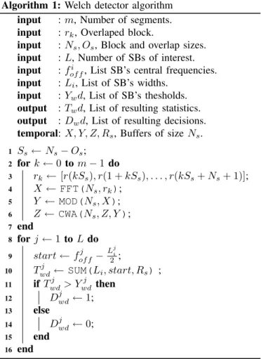
This section demonstrates the use of DiplodocusDF by describing the Welch periodogram application for opportunis-tic spectrum sensing, recently proposed in [22]. Welch peri-odogram helps to identify the significance of the frequency contributors in a signal by calculating sub-band’s energy, and comparing to its designated threshold. The algorithm is described in 1 and the model is shown in figure 3.
The line 3 in algorithm 1 describes the overlapping of block elements. This operation is modelled in figure 3 by component OVLP. The behaviour of OVLP is described in an activity diagram. It simply waits for the arrival of data blocks at its input port, whenever Ns elements are available, they are sent to the next component through the output port. After sending, the first Ns − Os elements are discarded. This process is repeated m times. The operation parameters (Ns, Os, etc.) are read from the input channel, which allows dynamic configuration of components.
The line 4 corresponds to the component FFT in the model. Here the input data is transformed to the frequency domain. The line 5 corresponds to MOD component in the model, there
the magnitude of each element of the input block is calculated. Line 6 accumulates the magnitude of each element of the block, this corresponds to CWA in the model. These three execution operations have similar behaviours, they wait for the input signals, after receiving them they are operated and the output is sent through the output port. In the case of CWA, it waits for the two input signals and they have to be present before proceeding. The difference between the operators is more important at runtime, described in section VI.
The components A, B and C are used to construct the data-flow loop of line 2. The A component is described in such a way that the first block is routed to the output port out2 (the lower one), the rest of the blocks are routed to the output port out1(upper one). It is important to note that each data-block carries its data-block identifier. The component B is described to retransmit from input port in1 only the first block, its port in2is always retransmitted. These components are executed when at least one of the input signals is available. Component C is described in such a way that the input is retransmitted through output out1 only when it is the number m − 1, the block is retransmitted through out2 in any other case.
The execution operator SUM corresponds to line 10, it adds the elements of the received block and sends the one-element result block through its output. The REP receives one full block of Ns elements and sends L sub-blocks of its corresponding Li size. The parameters (L, Li, fof fi ) are also received as part of the input block information. The COLL data-flow operator receives m one-element blocks and sends one block of m elements. The DES operator receives the block and compares each of its elements to its corresponding thresh-old Ywd. DES generates a block of L elements containing the decisions for each element (sub-band). This corresponds to the output of the Welch periodogram model, which will activate a next operator in the overall model.
VI. RUNTIME ENVIRONMENT
The applications are executed with the support of a runtime environment. The functioning of the environment is depicted in figure 4, which shows a configuration made of n applications that are executed on a m+ 1 processors platform. One of the processors (general purpose) is on charge of executing the co-ordination applications, the rest of the processors (potentially specialized) execute the SDR operations.
The runtime environment architecture follows a data-driven approach. In a data-driven approach, the functions are ex-ecuted when its input data is available. It was said before that a DiplodocusDF model is translated into a coordination application. The coordination applications are composed of a runtime, a set of coordination functions (list CF in figure 4), one for each operator in the model, and a set of signals (list S in figure 4), one for each dataflow link. The runtime executes the functions when its input signals are valid. This is similar to what happens at model level. It was chosen in this way in order to maintain the determinism and parallelism properties as described by the model. It also allows to generate
Fig. 3: Welch detector design based on DiplodocusDF profile.
Algorithm 1: Welch detector algorithm input : m, Number of segments. input : rk, Overlaped block.
input : Ns, Os, Block and overlap sizes. input : L, Number of SBs of interest. input : fi
of f, List SB’s central frequencies. input : Li, List of SB’s widths.
input : Ywd, List of SB’s thesholds. output : Twd, List of resulting statistics. output : Dwd, List of resulting decisions. temporal: X, Y, Z, Rs, Buffers of size Ns. 1 Ss← Ns− Os; 2 for k ← 0 to m − 1 do 3 rk ← [r(kSs), r(1 + kSs), . . . , r(kSs+ Ns+ 1)]; 4 X ← FFT(Ns, rk); 5 Y ← MOD(Ns, X); 6 Z ← CWA(Ns, Z, Y ); 7 end 8 for j ← 1 to L do 9 start ← fof fj −L j i 2 ; 10 Twdj ← SUM(Li, start, Rs); 11 if Twdj > Ywdj then 12 Djwd← 1; 13 else 14 Djwd← 0; 15 end 16 end
regular code, predictable from the model, as suggested in [3] for effective model-driven design.
The coordination function manages the parameters of the SDR operations,and sets them for execution by aggregating them into the execution queue of a co-processor. In figure 4, there are m ordered priority lists (oP Lm) which hold the operations from all the applications in the configuration. The ordered list is reordered every time a new operation is pushed into, such a way that a pop from the list will return the operator with the highest priority. The idea is to keep the co-processors in constant execution.
The scheduling of the coordination applications is done in a cooperative way, similar to the time-triggered hybrid (TTH) approach proposed in [23], where a set of software
applications are executed according to a schedule defined before of execution. The applications cannot preempt each others but can be preemted by a third type of tasks that are interrupt dependent, for example, an interrupt coming from a analog-to-digital converter, signalling the reception of data. Another source of interruption can be an specialized co-processor signalling that it is ready to execute another SDR operation. The interruption routines should be very quick, such a way that its execution does not deviate significantly the static scheduling of the coordination applications.
S S
S CF CF CF
P roc1
App1 App2 Appn
ISRx
P rocm
P roc2
oP L1 oP L2 oP Lm
Fig. 4: Runtime environment
In the coordination functions, there are two main classes of objects, the coordination functions (CF) and the signals (S). Each CF object corresponds to one of the components from the its DiplodocusDF model. Each S object in the system corresponds to one of the dataflow links. The CF class has two properties, CF id, and CR priority. The Signal class is more complex, it does not carry the actual data but its location in memory. This is platform dependent information that is added to the model by the user at mapping time. For the case of expressMIMO, the signal parameters are: Base address, length of data vector, data type, memory bank, and memory block. It also includes a valid flag to indicate when the data is ready to be read. The Operator class has four methods: The constructor, the execution, the signalRule, and the destructor. The constructor method initializes the parameters of its corresponding output signal(s). That means that the operators know in advance where in memory they will write their results. This information is captured in the model by the user at mapping time. There is also the execution method, which implements a c-language version of its activity diagram in the model of figure 3. The method is implemented in a
run-to-completion approach, i.e. the method should not block. The signalRule method is used to evaluate the signal condition before firing the execution method. For example, while the A component is executed whenever one of its inputs is valid, the CWA component requires both input signals to be present.
The target system is depicted in figure 5. The applications run on top of a real-time operating system, including the run-time support. The target is very general, it can be customized for any platform. Porting a configuration from one platform to another would require changing the hardware abstraction layer and the drivers in figure 5, the rest would remind the same.
Platform HAL Kernel Libraries Drivers Runtime support App2 App1 Appn
Fig. 5: Target system architecture
VII. CONCLUSIONS
This work presents model-driven design methodology to overcome the deficiencies of current design flows for software defined radio applications. This work is in progress and much remains to be defined and implemented. However, the described domain-specific UML profile meets the require-ments for a MDD methodology, it captures the semantics of SDR applications, and allows the implementation of the envisioned synthesis mechanisms, and allows automatic code generation. Also, a runtime environment was described, to support the execution of the generated code. A software defined radio application was designed to demonstrate the use of DiplodocusDF language. The model was simulated using the capabilities of Ttool and the model was translated into C-language, compiled, and executed successfully.
So far, the translation mechanisms requires a detailed model description, including the memory management solutions, further research efforts will be dedicated to generate memory management solutions automatically. Also, the current runtime implements a time- triggered scheduling approach, mixed with preemtive interrupt service routines. We will work on the def-inition and implementation of educated scheduling solutions based on model simulation results.
REFERENCES
[1] T. Ulversoy, “Software defined radio: Challenges and opportunities,”
Communications Surveys Tutorials, IEEE, vol. PP, no. 99, pp. 1–20, 2010.
[2] D. Nussbaum, K. Kalfallah, R. Knopp, C. Moy, A. Nafkha, P. Leray, M. Delorme, J. Palicot, J. Martin, F. Clermidy, B. Mercier, and R. Pacalet, “ropen platform for prototyping of advanced software defined radio and cognitive radio techniques,” in Digital System Design,
Archi-tectures, Methods and Tools, 2009. DSD ’09. 12th Euromicro Conference on, 27-29 2009, pp. 435–440.
[3] D. Schmidt, “Guest editor’s introduction: Model-driven engineering,”
Computer, vol. 39, no. 2, pp. 25–31, feb. 2006.
[4] R. France, S. Ghosh, T. Dinh-Trong, and A. Solberg, “Model-driven development using uml 2.0: promises and pitfalls,” Computer, vol. 39, no. 2, pp. 59–66, feb. 2006.
[5] B. Selic, “The pragmatics of model-driven development,” Software,
IEEE, vol. 20, no. 5, pp. 19–25, sept.-oct. 2003.
[6] L. Apvrille, J.-P. Courtiat, C. Lohr, and P. de Saqui-Sannes, “Turtle: a real-time uml profile supported by a formal validation toolkit,” Software
Engineering, IEEE Transactions on, vol. 30, no. 7, pp. 473–487, july 2004. [Online]. Available: http://labsoc.comelec.enst.fr/turtle/ttool.html [7] G. Papadopoulos, “Automatic code generation: A practical approach,” in
Information Technology Interfaces, 2008. ITI 2008. 30th International Conference on, june 2008, pp. 861–866.
[8] Y. Zhu, Z. Sun, W.-F. Wong, and A. Maxiaguine, “Using uml 2.0 for system level design of real time soc platforms for stream processing,” in
Embedded and Real-Time Computing Systems and Applications, 2005. Proceedings. 11th IEEE International Conference on, aug. 2005, pp. 154–159.
[9] J. Vidal, F. de Lamotte, G. Gogniat, J.-P. Diguet, and P. Soulard, “Uml design for dynamically reconfigurable multiprocessor embedded systems,” in Design, Automation Test in Europe Conference Exhibition
(DATE), 2010, march 2010, pp. 1195–1200.
[10] J. Vidal, F. de Lamotte, G. Gogniat, P. Soulard, and J.-P. Diguet, “A co-design approach for embedded system modeling and code generation with uml and marte,” in Design, Automation Test in Europe Conference
Exhibition, 2009. DATE ’09., april 2009, pp. 226–231.
[11] T. Moreira, M. Wehrmeister, C. Pereira, J.-F. Petin, and E. Levrat, “Automatic code generation for embedded systems: From uml specifi-cations to vhdl code,” in Industrial Informatics (INDIN), 2010 8th IEEE
International Conference on, july 2010, pp. 1085–1090.
[12] I. et al Perseil, “An efficient modeling and execution framework for complex systems development,” in Engineering of Complex Computer
Systems (ICECCS), 2011 16th IEEE International Conference on, april 2011, pp. 317–331.
[13] M. Brun, J. Delatour, and Y. Trinquet, “Code generation from aadl to a real-time operating system: An experimentation feedback on the use of model transformation,” in Engineering of Complex Computer Systems,
2008. ICECCS 2008. 13th IEEE International Conference on, 31 2008-april 3 2008, pp. 257–262.
[14] P. Green and S. Essa, “Integrating the synchronous dataflow model with uml,” in Design, Automation and Test in Europe Conference and
Exhibition, 2004. Proceedings, vol. 1, feb. 2004, pp. 736–737 Vol.1. [15] H. St¨orrle, “Semantics of uml 2.0 activities with data-flow,” 2004. [16] J. Dennis, “Data flow supercomputers,” Computer, vol. 13, no. 11, pp.
48–56, nov. 1980.
[17] C. Jaber, A. Kanstein, L. Apvrille, A. Baghdadi, P. Le Moenner, and R. Pacalet, “High-level system modeling for rapid hw/sw architecture exploration,” in Rapid System Prototyping, 2009. RSP ’09. IEEE/IFIP
International Symposium on, june 2009, pp. 88–94.
[18] L. Apvrille, W. Muhammad, R. Ameur-Boulifa, S. Coudert, and R. Pacalet, “A uml-based environment for system design space explo-ration,” in Electronics, Circuits and Systems, 2006. ICECS ’06. 13th
IEEE International Conference on, dec. 2006, pp. 1272–1275. [19] B. Kienhuis, E. Deprettere, K. Vissers, and P. Van Der Wolf, “An
approach for quantitative analysis of application-specific dataflow archi-tectures,” in Application-Specific Systems, Architectures and Processors,
1997. Proceedings., IEEE International Conference on, Jul. 1997, pp. 338–349.
[20] G. Kahn, “The semantics of a simple language for parallel program-ming,” in IFIP Cong., 1974.
[21] N. Halbwachs, P. Caspi, P. Raymond, and D. Pilaud, “The synchronous data flow programming language lustre,” Proceedings of the IEEE, vol. 79, no. 9, pp. 1305–1320, sep 1991.
[22] A. Hekkala, I. Harjula, D. Panaitopol, T. Rautio, and R. Pacalet, “Cooperative spectrum sensing study using welch periodogram,” in
Telecommunications (ConTEL), Proceedings of the 2011 11th Interna-tional Conference on, june 2011, pp. 67–74.
[23] M. J. Pont, “Applying time-triggered architectures in reliable embedded systems: challenges and solutions,” e & i Elektrotechnik und
Informationstechnik, vol. 125, pp. 401–405, 2008, 10.1007/s00502-008-0587-z. [Online]. Available: http://dx.doi.org/10.1007/s00502-008-0587-z