HAL Id: hal-01863188
https://hal.archives-ouvertes.fr/hal-01863188
Submitted on 28 Aug 2018
HAL is a multi-disciplinary open access
archive for the deposit and dissemination of
sci-entific research documents, whether they are
pub-lished or not. The documents may come from
teaching and research institutions in France or
abroad, or from public or private research centers.
L’archive ouverte pluridisciplinaire HAL, est
destinée au dépôt et à la diffusion de documents
scientifiques de niveau recherche, publiés ou non,
émanant des établissements d’enseignement et de
recherche français ou étrangers, des laboratoires
publics ou privés.
Secondary creep behavior of Zr-4 claddings under LOCA
conditions
Damien Campello, Nicolas Tardif, Marie-Christine Baietto, Michel Coret,
Jean Desquines
To cite this version:
Damien Campello, Nicolas Tardif, Marie-Christine Baietto, Michel Coret, Jean Desquines. Secondary
creep behavior of Zr-4 claddings under LOCA conditions. Top Fuel 2016, Sep 2016, Boise, United
States. �hal-01863188�
Secondary creep behavior of Zr-4 claddings under LOCA
conditions
Damien Campello,
1Nicolas Tardif,
1M.-C. Baietto,
1Michel Coret,
2and Jean
Desquines
31Université de Lyon, CNRS, INSA-LYON, LaMCoS UMR 5259, 20 Avenue Albert Einstein, F69621 Villeurbanne
Cedex, France
2GeM (UMR 6183), Ecole Centrale de Nantes, 1 rue de la Noë, 44321 Nantes, France 3IRSN/PSN-REX/SEREX/LE2M, Saint Paul lez Durance, France
+33 (0)4 72 43 64 89, damien.campello@insa-lyon.fr
Abstract
The thermo-mechanical behavior of Zircaloy-4 fuel rods under Loss-Of-Coolant Accident (LOCA) conditions is investigated. A custom experimental setup is dedicated to the high-temperature creep ballooning study of 90mm long cladding samples. Creep tests were performed under an inert environment (argon), for temperatures from 750 to 850 °C and internal pressures ranging from 1 to 5MPa. During its operating life, Zr-4 cladding is submitted to oxidation and hydriding. These parameters strongly influence the creep behavior of Zirconium alloys at high temperatures. A first campaign on as-received Zr-4 was performed.
Creep-rates are computed using 2-Dimensional Digital Image Correlation (2D-DIC) and are correlated to local temperatures measured using Near Infra-Red thermography. As-received Zr-4 behavior laws are determined using Finite Element Model Updating (FEMU). Norton exponents and activation energies are determined for thermal-mechanical conditions of the performed tests. The stress and temperature effects on the steady-state creep parameters are highlighted in this study.
Keywords: Zr-4, FEMU, creep-rate map, steady-state creep law.
I.
INTRODUCTION
Loss-Of-Coolant of the primary loop is a complex multi-physical design basis accident. The study of the thermal mechanical and thermal hydraulics behavior of a fuel rod assembly is the context of PERFROI project [1]. It relies on both experimental and modeling activities about the flow blockage caused by fuel rods deformation, fuel fragment relocation and the potential loss of cladding integrity. In this framework, the ballooning behavior of fuel rod claddings submitted to high temperature and internal pressure is investigated.
Creep-tests and thermal ramps are usually performed in order to investigate the cladding behavior under LOCA conditions [2-5]. The setups proposed in this literature provide on a test a single temperature condition assuming thermal field is homogeneous when testing. A unique stress condition is often investigated. The number of the tests to be performed is consequent in order to accurately determine material parameters.
The study focuses on creep ballooning tests. Creep power-law in equation (1) is assumed to well model the secondary-creep behavior
𝜀̇
𝑒𝑞 of zirconium alloys [6] depending on the temperature T and the von Mises stress𝜎
𝑣𝑀. The multiplicative coefficient A, the Norton exponent n and the activation energy Q are widely investigated with experimental studies.𝜀̇𝑒𝑞(𝜎, 𝑇) = 𝐴. 𝜎𝑣𝑀𝑛. 𝑒 −𝑄
These creep parameters depend on the temperature and applied stress conditions. The parameters derived from tests are often considered as valid over large temperature range [3-4].
Experimental mechanics measurements have been increasingly improved using digital image techniques. Digital Image Correlation [7] (DIC) is now widely performed to get strain fields from 2-Dimensional (2D), 3D or even volume measurements. The use of infra-red and near infra-red [8-9] thermography is also expanding with thermal field measurements. Recent material identification procedures [10] are taking advantages of such rich measurement databases.
The experimental setup designed by Tardif et.al. [11] has been adapted [12] in order to perform ballooning creep tests on Zr-4 claddings. A single test provides creep-rate data on a 20°C temperature range. Two or three internal pressure loadings are applied addressing to different stress levels. Tests are instrumented for performing 2D-DIC and near infra-red thermography. FEMU [13] is then performed in order to determine the creep parameters addressing to the thermal-mechanical conditions of the test. Results on as-received Zr-4 specimens are presented and discussed in section III.
II.
MATERIAL AND METHODS
Steady-state creep behavior of as-received Stress Relieved (SRA) Annealed Zr-4 is investigated in this study. Outer diameter D and thickness w of the specimens are respectively 9.5mm and 0.57mm. Claddings are cut using an electro discharge machining into 90mm long samples. Eccentricities Ξ were estimated between 1 and 3% using equation (2).
𝛯 =𝑤𝑚𝑎𝑥− 𝑤𝑚𝑖𝑛
𝑤𝑚𝑎𝑥+ 𝑤𝑚𝑖𝑛 (2)
Experimental bench
Scheme of the tests
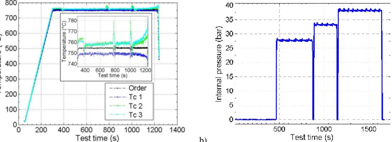
The experimental setup aims to cover a 20°C temperature range and several stress levels in a single test. The specimen is first heated up temperature of interest then three internal pressure levels are successively applied as plotted in Figure 1. Steady-state creep rates are expected for each mechanical loading.
a) b)
FIGURE 1. Temperature measurements are plotted in a). Measurements were performed using 6 thermocouples. Internal
pressure is plotted over test time in b). The three pressure levels are 2.17, 2.89 and 3.51MPa.
The bench and the processing methods are detailed in the following. Test setup
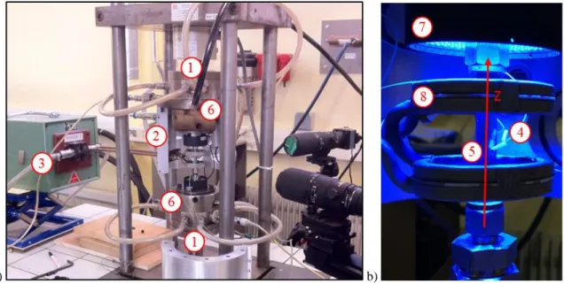
The whole assembly represented in Figure 2 is set on a 10kN servo-hydraulic tensile device (mark 1). Experiments were performed under an inert environment (argon gas) within an enclosure (mark 2) in order not to oxidize the specimen. The samples are heated up using an induction system (mark 3). The temperature is regulated using a thermocouple (mark 4) spot-welded on the specimen (mark 5). The combination of induction heating and water cooled custom grips (mark 6) leads to a non-uniform temperature distributed along axial direction. Internal pressure (argon
gas) is regulated using a pressure reducer and is measured within the two jaws using pressure gauges. The bottom-end effect is compensated using a compressive force.
Specimen is set on jaws using Swagelok connectors performing the gas sealing. Cladding is prepared with a black undercoating and a white speckle pattern is sprayed. The sample is observed through sapphire glasses using cameras distributed over the enclosure circumference. The specimen is uniformly illuminated using blue pulsing LED rings (mark 7) disposed above and below the induction coils (mark 8). At least one camera is dedicated to kinematics measurements and one another to thermal measurements. First camera is fitted with blue band-pass filters and synchronized with the LED pulses. The high temperature specimen radiation is filtered this way as proposed by Pan et al. [14]. It is a requirement for performing 2D-DIC measurements. Second camera registers the specimen radiation. Each camera is fitted with a 200mm macro lens.
a) b)
FIGURE 2. Experimental setup a) and the zone of interest b).
Digital image methods
The heterogeneous thermo-mechanical conditions are fully capitalized using both thermal and kinematics field measurements along the Region Of Interest (ROI).
Axial and hoop displacements fields are calculated in the ROI using a 2D-DIC algorithm. It is performed using Ufreckles software developed at LaMCoS by J. Réthoré [15]. The conservation of the optical flow is solved using a non-linear least-square method relying on a finite element basis. Performing 2D-DIC on tubular specimen is not common considering the 3D geometry. Uncertainties related to out-of-plane displacement (ballooning) have been estimated and are negligible with respect to the cladding deformation when steady-state creep rates are calculated. Displacements and strains fields extracted from DIC calculation are exposed in figure 3. Note that the spatial data used in the following are those in the red boxes in Figure 3, corresponding to the tube generatrix facing the camera.
FIGURE 3. Axial and hoop displacements are presented in a) and b) with the deformed mesh in a). They correspond to the end of
the third internal pressure loading. Axial and hoop strains are plotted in c) and d). The hoop strain peak is evaluated to 9.8%.
Logarithmic strains are calculated using axial and hoop displacements. Equivalent strains are derived assuming the material incompressibility. The steady-state creep-rates are finally determined along the axial direction for each internal pressure loading.
The second digital image processing is dedicated to near infra-red measurements [9]. Standard cameras (with silicon detectors) are preferred to infra-red cameras in order to higher the image definition. The K1 and K2 parameters of the
radiometric model detailed in equation (3) are calibrated using the data addressing to the specimen heating.
𝑇 = 𝐾1 ln(𝐾2
𝐼 + 1)
(3)
Grey level intensities are measured using digital thermocouples (see the red and yellow boxes in Figure 4) located close to real ones and correlated to the temperature measurements.
FIGURE 4. The radiometric model is calibrated using the thermocouple measurements on the specimen itself during the heating
and grey level intensities computed using digital thermocouples located near the real ones.
Once calibrated the model computes the temperature distribution along axial direction from grey level intensities. The distribution is corrected using the 3 thermocouple measurements.
To summarize with the experimental part, pressure and temperature distributions are measured. Steady-state creep rate distributions are calculated for the three internal pressure loadings. A finite element model of the test is updated for fitting these kinematics data.
Identification method
The heterogeneous thermo-mechanical conditions are fully capitalized with both thermal and kinematics field measurements along the Region Of Interest (ROI). An iterative Gauss-Newton algorithm is then performed in order to lower the error between experimental creep-rate logarithms and calculated ones. The FEM is first introduced and the optimization process in then detailed.
Tests modeling
a) b) c)
FIGURE 5. The model and the boundary conditions are represented in a) and b). A deformed regular CAX4I is plotted
in c).
FEM calculation of the tests were performed using the commercial software Abaqus. The axisymmetric modeling represented in Figure 5 is chosen regarding the kinematics and thermal distribution calculated from different point of views. Elastic behavior is modeled using equation (4).
𝐸(𝑇) = 116.1𝐸9− 59𝐸6. 𝑇 (Pa) (4)
The thermal expansion coefficient is 6.10-6C-1. Steady-state creep power-law of equation (1) to be determined is
modeled using the user CREEP routine.
A follower pressure is imposed using the experimental data. The temperature distribution determined using NIR measurements in the ROI is extended to the total model length using a sinus sum. Several thermal profiles are imposed at different test times using the user UTEMP routine.
FEMU
An initial parameters set is guessed. The pressure and thermal measurements are processed for modeling the experiment. Once the FEM calculation is performed, the least-squares error er in equation (5) is outputted.
𝑒𝑟 = ‖log(𝜀̇𝑐𝑎𝑙) − log(𝜀̇𝑒𝑥𝑝)
log(𝜀̇𝑒𝑥𝑝) ‖2 (5)
Gauss-Newton algorithm is then applied to lower this error. The problem is linearized using the creep-rate logarithms and the solution to be determined is [ln(A), n , Q]. The methodology was validated using a FEM virtual experiment.
a) b)
FIGURE 6. The experimental and calculation data are compared in this figure. Equivalent creep strains are plotted over time in
a) for two different axial positions (z=-2mm for the dot lines, and z=6mm for the solid ones). Axial and hoop strains are plotted over time in b) for the same axial positions.
Once the optimized parameters are determined, the model is considered as valid over the measured temperature range. The FEM calculation are processed in order to determine the von Mises stress range of validity. Experimental equivalent creep strains versus test time are compared with calculated ones in Figure 6.a). The axial and hoop strains versus test time are also compared in Figure 6.b). Even if the creep is only modeled using secondary-creep power-law and the parameters are determined comparing three creep-rate distributions, the calculated creep strains are very close to the measurements. Note that a single creep behavior law is often not sufficient to accurately model the tube ballooning for the three internal pressure loadings of a single experiment.
III.
RESULTS
The proposed methodology were applied to seven experiments for temperatures ranging from 750 to 850°C and internal pressures from 1 to 5MPa.
Test conditions
Table 1 summarizes the experimental conditions of each tested specimen. Note that only 2 thermocouples (Tc) were visible on experiment AR-7 from NIR camera point of view. A 10°C difference was however measured between the thermocouples. It was sufficient to accurately calibrate the radiometric model.
TABLE 1. Characteristics of the experiments. Specimen Temperature range (K) Internal pressures (MPa) Number of visible Tc Number of identification steps
Pixel size of DIC measurements (µm) AR-1 [1099,1123] [1.04,1.65,2.24] 3 2 9.1 AR-2 [1103,1123] [2.17,2.89,3.51] 3 1 9.5 AR-3 [1078,1098] [2.75,3.33,3.86] 3 2 10.0 AR-4 [1053,1078] [1.48,2.66] 3 1 9.6 AR-5 [1048,1069] [2.75,3.33,3.86] 3 2 8.7 AR-6 [1048,1073] [4.03,4.52,5.04] 3 2 7.3 AR-7 [1013,1033] [3.05,3.70,4.89] 2 2 9.2
Determined parameters and creep-rate maps
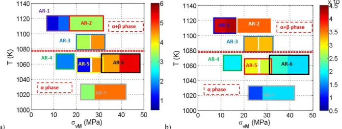
The stress exponent n and activation energy Q are the parameters of interest. The results of the identification process are plotted in Figures 7 and 8.a) representing the Norton exponent and activation energies versus the measured temperature and calculated von Mises stress. Each colored box corresponds to thermal-mechanical conditions associated to a single experiment. The determined stress exponents are consistent between the tests. Norton exponent value increases with increasing von Mises stress for a constant temperature. Dislocation creep-rate is known to be
strongly correlated to applied stress. A well-defined transition between low stress exponent and high stress exponent is clearly evidenced in this figure.
a) b)
FIGURE 7. Determined a) stress exponent and b) activation energies (J/mol) are plotted over stresses and temperatures.
The determined activation energies are plotted in Figure 7.b) and are also consistent between various tests. The activation energies in the α-phase domain are ranging from 123 to 291kJ/mol. Q magnitude is increasing from α-phase to (α+β)-phase domains. The transition regime from α to (α+β)-phase is clearly evidenced at 1080K.
TABLE 2. Parameters determined and thermos-mechanical validity. Specimen Temperature
(K)
von Mises stress (MPa) ln(A) (MPa-ns-1) n Q (kJ/mol) AR-1 [1099,1123] [7,12]/[12;17] 33.5/33.2 0.96/1.64 416/430 AR-2 [1103,1123] [17,32] 21.4 3.42 359 AR-3 [1078,1098] [20,26]/[26,32] 17/12.6 3.5/4.5 329/321 AR-4 [1053,1078] [11,19] 6.97 1.8 193 AR-5 [1048,1069] [20,26]/[27,32] 20/7.32 1.2/4.5 291/275 AR-6 [1048,1073] [31,39]/[39,48] 1.37/-5.67 4.4/5.4 215/183 AR-7 [1013,1033] [22,28]/[28,42] -5.69/-3.33 3.3/4.7 123/184 Table 2 summarizes the final results of the processed tests on as-received Zr-4 specimens.
Comparison with literature data
Creep-rate logarithms are finally plotted in Figure 8.a).
a) b)
FIGURE 8. Creep-rate logarithms are plotted in figure a) over stresses and temperatures of the processed tests. Test results are
The α–phase behavior law proposed by Kaddour et al. [3] is plotted in Figure 8-b) in the diffusion and dislocation regimes. Stress exponents and activation energies of these two regimes are respectively 1.3-5 and 190-316kJ/mol. The determined creep-rate magnitudes are consistent with those proposed by Kaddour et al..
The 360kJ/mol activation energy magnitude in the (α+β)-phase domain was experimentally determined by Garde et al. [16]. It corresponds to a grain boundary sliding creep mechanism.
Norton exponents and activation energies determined in the study are consistent with the Rosinger et. al. database detailed in [4].
IV.
CONCLUSION
Creep-rate logarithms map is presented in the framework of as-received Zr-4 cladding ballooning under LOCA conditions. A FEMU methodology were performed in order fully capitalize high-temperature creep ballooning tests data and determine the parameters a steady-state creep power-law. The ballooning structural effect are accounted for using FEM granting access to the true stress level and state over a 20mm gauge length. Results of seven tests are detailed in this paper addressing to thermal conditions ranging from 750 to 850°C and von Mises stresses in a range of 7 to 48MPa.
The effect of applied stress on the Norton exponent is evidenced in the study for both α-phase and (α+β)-phase domains. The determined stress exponent magnitudes are very consistent with literature data depending on the thermo-mechanical test conditions.
The activation energy parameter is very sensitive to the thermo-mechanical conditions and remains valid within a limited temperature and stress ranges to the authors’ knowledge. The beginning of the (α+β)-phase domain is clearly identified with the activation energy increase.
Finally, steady-state creep is accurately modeled depending on ballooning thermo-mechanical conditions.
Further work will be dedicated to the analysis of the creep parameters variation depending on the temperature and applied stress conditions. A creep mechanism map based on Norton exponents and activation energies magnitude is expected from this analysis.
During their operating life, Zr-4 claddings microstructure is modified due to high temperature water contact. In order to be more representative of the high temperature creep behavior of the alloy, similar creep tests will be performed on pre-hydrided and both pre-hydrided / pre-oxidized specimens.
ACKNOWLEDGMENTS
The study was performed in the framework of the PERFROI ANR project (n°ANR-11-RSNR-0017-01). The authors would like to acknowledge all the participants of the project: EDF, IRSN-SEREX, LEMTA, Ecole Centrale of Paris.
REFERENCES
[1] Repetto, G., Dominguez, C., Durville, B., Carnemolla, S., Campello, D., Tardif, N., and Gradeck, M., “The R&D PERFROI project on the thermal mechanical and thermal hydraulics behaviors of a fuel rod assembly during Loss-Of-Coolant Accident,” Proceedings of the Nureth16, Chicago, USA, August 30-September 4, (2015).
[2] Busby, C., and Marsh, K., “High temperature, time-dependent deformation in internally pressurized Zircaloy-4 tubing (LWBR Development Program),” in Tech. report, Colorado Cooperative Wildlife Research Unit, Fort Collins, USA, (1974). [3] Kaddour, D., Frechinet, S., Gourgues, A., Brachet, J., Portier, L., and Pineau, A., “Experimental determination of creep
properties of zirconium alloys together with phase transformation,” Scripta Materialia, 51, 6, (2004), 515-519. [4] Rosinger, H. E., Bera, P. C., and Clendening, W. R., “The steady-state creep of Zircaloy-4 fuel cladding from 940 to
1873K”, in Tech. report, Atomic Energy of Canada Limited, (1978).
[5] Réocreux, M., and de Martinville, E. S., “A study of fuel behavior in PWR design basis accident: and analysis of results from the PHEBUS and EDGAR experiments,” Nuclear Engineering and Design, 124, 3, (1990), 363-378.
[6] Hayes, T. A., and Kassner, M., “Creep of zirconium and zirconium alloys,” Metallurgical and Materials Transactions A,
[7] Sutton, M., Wolters, W., Peters, W., Ranson, W., and McNeill, S., “Determination of displacements using an improved digital correlation method,” Image and vision computing, 1, 3, (1983), 133-139.
[8] Maynadier, A., Poncelet, M., Lavernhe-Taillard, K., and Roux, S., “One-shot measurement of thermal and kinematic fields: Infrared Image Correlation (IRIC),” Experimental Mechanics, 52, 3, (2012), 241-255.
[9] Meriaudeau, F. “Real time multispectral high temperature measurement: Application to control in the industry,” Image and vision computing, 27, 7, (2007), 1124-1133.
[10] Avril, S., Bonnet, M., Bretelle, A. S., Grediac, M., Hild, F., Ienny, P., Latourte, F., Lemosse, D., Pagano, S., Pagnacco, E., and Pierron, F., “Overview of identification methods of mechanical parameters based on full-field measurements,” Experimental Mechanics, 48, (2008), 381-402.
[11] Tardif, N., Coret, M., and Combescure, A., “Experimental study of the fracture kinetics of a tubular 16MnNiMo5 steel specimen under biaxial loading at 900 and 1000°C. Application to the rupture of a vessel bottom head during a core meltdown accident in a pressurized water reactor,” Nuclear Engineering and Design, 241, 3, (2011), 755-766.
[12] Campello, C., Baietto, M. C., Coret, M., Tardif, N., and Desquines, J., “Thermo mechanical behavior of fresh zircaloy-4 under LOCA conditions,” 13th International Conf. on Creep and Fracture of Engineering Materials and structures (CREEP-15), Toulouse, France, May 31 –June 04, (2015).
[13] Kavanagh, K. T., and Clough, R. W., “Finite element applications in the characterization of elastic solids,” International Journal of Solids and Structures, 7, 1, (1971), 11-23.
[14] Pan, B., Wu, D., Wand, Z., and Xia, Y., “High-temperature digital image correlation method for full field deformation measurement at 1200°C,” Measurement Science and Technology, 22, 1, (2011).
[15] Réthoré, J., Hild, F., and Roux, S., “Shear-band capturing using a multiscale extended digital image correlation technique,” Computer Methods in Applied Mechanics and Engineering, 196, 49, (2007), 5016-5030.
[16] Garde, A. M., Chung, H. M., and Kassner, T. F., “Micrograin superplasticity in Zircaloy at 850°C,” Acta Metallurgica, 26, 1, (1978), 153-166.