Simulation of contact on crack lips and its influence on fatigue
life prediction
O. Pierard1, Y. Jin1, E. Wyart1, B. Dompierre1 and E. Béchet2
1 Cenaero, 29, rue des frères Wright, 6041 Gosselies, Belgium,
olivier.pierard@cenaero.be, yuan.jin@cenaero.be, eric.wyart@cenaero.be, benoit.dompierre@cenaero.be
2 LTAS - Département Aérospatial et Mécanique, Université de Liège, Quartier
Polytech, Allée de la Découverte 9, B-4000 Liège, Belgium, eric.bechet@cenaero.be
ABSTRACT. This work is dedicated to evaluate the influence of the contact on crack
lips on crack path and crack growth rate under multi-axial loading conditions. An important part is dedicated to algorithmic robustness when handling contact in the context of XFEM in presence of crack tip enrichment functions. Crack path predictions as well as crack growth rate are also strongly influenced by the partial contact so that expressions classically used in the context of uniaxial loading without contact must be adapted. Preliminary simulations of a cracked cylinder submitted to four points bending under multiaxial loading conditions are presented and will be compared to experimental results.
INTRODUCTION
Multiaxial crack propagation simulation under fatigue is a challenging topic which requires a lot of attention to guarantee accurate results. All the classically used hypothesis for uniaxial simulation must be reviewed such as the computation of the equivalent stress intensity factors and the bifurcation criteria.
Even if the mechanical loading occurs in a single direction, the crack can endure more complex situations due to its orientation inducing mixed-mode, (partial) contact on crack lips and/or presence of residual stresses.
Simulation of crack propagation in presence of contact on crack lips with the eXtended Finite Elements Method (XFEM) is the core topic of this work. Several algorithms have been proposed in order to apply contact conditions in a stable way on the implicitly represented crack lips which are for the first time combined to crack propagation.
This paper is organized as follow. In a first section, the problem is described as well as the augmented Lagrangian method to solve the contact problem. Then, these equations are discretized in the context of the XFEM method and adopted algorithms to model contact are presented. Robustness and efficiency are illustrated on a 2D uniaxial test case without propagation for which an analytical solution is available. Next,
classical rules used in uniaxial and proportional loading to predict crack path and crack growth rate are discussed in the context of multiaxial loading and presence of contact. Finally, a 3D multi-axial example is proposed in order to highlight the capability of the algorithms in presence of partial contact.
PROBLEM DESCRIPTION
Let's consider a cracked body with a boundary subjected to tractions on part of the interface and to Dirichlet boundary conditions on . denotes the cracked interface . Equations governing this homogeneous isotropic linear elastic problem in absence of body forces are:
(1) (2) (3) (4) where is the second-order stress tensor, is the small strain tensor and is the fourth-order Hooke tensor. is the normal to the boundary, is the divergence operator, '.' denotes a contraction over one indice and ':' denotes a double contraction.
Signori's contact condition on crack lips reads:
(5) (6) (7) where denotes the normal stress vector and is the normal displacement jump across the crack. This condition imposes that at a given point , either crack lips are locally in contact, either the crack is open and lips are locally stress-free.
Such a problem can be solved by a wide variety of methods: penalization, Lagrangian, augmented Lagrangian or Nietsche. In the context of this work, the Lagragian one is adopted. Its main advantage, with respect to the penalization, is that no arbitrary penalization term is added so that matrix conditionning of the system remains acceptable. Furthermore, no arbitrary inter-penetration between surfaces in contact is observed.
The weak form of the Lagrangian frictionless contact problem then reads, find (set of admissible displacments) and (set of admissible lagrangian multipliers) such that:
(8) (9) where and are well chosen spaces for test functions and , respectively.
The XFEM approach extends the classical finite element discretization of the displacement field of the problem (1-4) by adding shape functions to represent the displacement jump across the crack lips as well as crack tip dedicated functions to represent the stress singularity:
(10) where is the set of nodes of the mesh, is the set of nodes whose support is completely cut by the crack and is the set of nodes enriched by crack tip functions f:
(11) where represents the local polar coordinate system associated with each point of the crack front.
Lagrange multipliers are defined on the nodes whose support is fully or partially cut by the crack. The interpolation is based on the same linear shape functions that are used for the displacement field. With XFEM, a naive linear P1-P1 interpolation choice for the displacement and Lagrangian multipliers respectively is not stable and results in oscillations [1]. An adequate reduction of the Lagrangian multiplier space can efficiently address the problem [2,3]. Solution adopted in this work is the one from Béchet et al. [2] which imposes constant relations between well-selected Lagrangian multipliers. Stability of this approach has been proved on fully-cut geometries. In case of presence of crack (i.e. geometry is not fully cut) and crack tip enrichments, an equality relation is imposed between all the multipliers of the element containing the crack tip. We have proved that the use of enrichment functions does not violate the stability condition on the Lagrange multipliers [4].
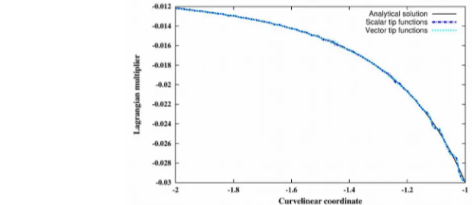
VALIDATION OF CONTACT ALGORITHMS (UNIAXIAL CONDITIONS) In order to validate contact algorithms, results from the numerical simulation of a 2D cracked infinite plate submitted to uniaxial tension is compared to the analytical solution [8]. Geometry and loading conditions are reported in Fig. 1. Due to the presence of the circular hole (stress raiser), contact forces (i.e. Lagrangian multipliers) will not be uniform along the crack lips.
The solution of the norm of the displacement field is illustrated in Fig. 2. It can be noticed that the displacement norm is almost null in the cracked area and, at least, the normal displacement to the crack lips is. This means that no interpenetration is observed, as expected, and that contact is well taken into account.
As an analytical solution is available for this problem, exact error in terms of energy norm can be computed. By doing this on several mesh refinements, the optimal convergence rate of 1 if considering a linear interpolation is reached. Another validation is to compare the value of the Lagrangian multipliers with the analytical solution. This is reported on Figure 3. An excellent agreement is obtained. A more detailed analysis of this problem is available in [4].
Figure 1. Uniform pressure imposed on the two sides of an infinite plate with a crack emanating from a circular hole.
Figure 2. Norm of displacement field for the infinite plate problem.
Figure 3. Evolution of Lagrangian multipliers along the crack lips - comparison of the analytical solution with XFEM solution (2 tip-enrichments functions are considered).
STRESS INTENSITY FACTORS COMPUTATION AND CRACK PROPAGATION ALGORITHMS
Based on the numerical solution of discrete problem (8-9), stress intensity factors (SIFs) are computed at a set of nodes along the crack front. This is based on the computation of interaction integrals (one for each fracture mode), including a correction in presence of contact as crack lips are not stress free any more:
(12)
where designates the interaction strain energy between the present state (1) of the numerical solution and a well chosen auxiliary state (2) which enables to extract the SIFs. Is the Kronecker's delta, is a direction normal to the crack front and tangent to the crack surface, is a weighting function and is the unit outward normal of C. Fatigue crack propagation is a point-by-point based process along the crack front which aims at predicting a deviation angle and a crack growth rate . The deviation angle is classically predicted with the maximum hoop stress criteria, i.e. the crack is growing in a direction perpendicular to the maximum hoop stress ( in a local reference frame aligned with the crack at the considered point):
. (13)
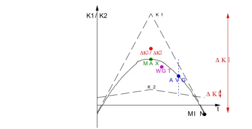
The '*' refers to a reference state during the propagation cycle. In case of proportional loading, the ratio remains constant during the whole load/unload cycle, so that choosing the reference state at the minimal load, maximal one or an intermediate one has no effect on . However, this is not the case any more in case of non proportional loading. A classical choice is using as reference point the intermediate load:
. (14)
However, this proposition suffers the fact that, in case of strong differences of mode mixity between the two load cases, the reference state is over-influenced by the minimum loading. To circumvent this limitation, it is proposed to weight the predicted angles for each load case by the corresponding equivalent SIF (see definition below):
(15) A comparison of all these criteria is illustrated on Figure 4.
Crack growth rate is based on a law valid at each point of the crack front function of the increment of equivalent stress intensity factor. A suitable crack propagation law when considering contact is the Elber one which can take into account the crack closure effect:
(16) where is the difference, at a given point along the crack front, between the equivalent stress intensity factor of the first and the second load (denoted and , respectively). Each one being computed from the stress intensity factors of the corresponding load:
. (17)
This expression is thus function of the propagation angle previously computed. It was initially developed for mode-I dominated propagation and must be used with care in case of strong mode-mixity along the crack front as well as in case of non-proportional loading (e.g. presence of residual stresses, partial contact,...).
In case of a maximum crack increment controlled propagation ( ), this increment is assigned to the point with the maximum , while increments of the other points on the crack front are given by . Once this is done, the two level sets representing implicitly the crack are updated according to the algorithm proposed by Duflot [6].
INFLUENCE OF CONTACT ON CRACK PROPAGATION WITH MULTIAXIAL BOUNDARY CONDITIONS
The example used in this section considers a cylinder subjected to 4-points bending, which is cracked in a V-notch at the middle of the bar, as illustrated on figure 5. With a null load ratio, almost no contact exists and the crack propagates in pure mode-I.
Figure 4. Various evaluation of the reference SIF ratio during one load cycle. t K1 / K2 MI N M A X A V G K 1 K 2 W G T
However, once crack reaches half of the cross-section, the cylinder is rotated of 90° so that partial contact on crack faces appears and the loading is becoming multi-axial. This problem has been described by Billardon [7] and experimental results are available.
In order to easily apply boundary conditions on a rotated specimen, at both ends of the cylinder, polyhedral cross sections (24 faces) are considered (see Fig. 6). Doing so, in the numerical model, forces are simply applied at the different locations instead of rotating the specimen (rotations must be a multiple of 15°).
After rotation, forces are imposed from the back to front side so that the previously generated crack becomes partially in contact, as illustrated on Figure 7. Top side is open while contact apply on the front side.
Figure 5: Experimental setup of the cylinder bar submitted to 4 points bending [7].
Figure 6: Mesh used for the numerical simulation; Polyhedral sectors are considered at both ends for BCs applications; V-notch containing the crack is highly refined
Figure 7: Illustration of partial contact during crack propagation after rotation: top side of the crack is open while front one is closed.
In the context of this work, a comparison of the numerical results when considering or not the contact will be confronted to the experimental results. Furthermore, following points will be discussed in the context of multi-axial crack propagation in presence of contact: choice of the propagation law, computation of the equivalent SIF increment and choice of the reference state to compute the propagation angle.
DISCUSSION
Handling partial contact in crack propagation simulation under multi-axial loading conditions is a complex task which requires a lot of attention to obtain accurate predictions. First of all, robust algorithms must be adopted in order to tackle numerical problems due to presence of contact in an XFEM context. Secondly, model choices must be used with care and eventually adapted, as for the computation of the equivalent SIF increment and the choice of the reference state. Even if these concepts are described in the context of this work, an in-depth analysis of these effects will be presented during the conference.
REFERENCES
1. Ji, H., Dolbow, J.E. (2004) Int. J. Num. Meth. Eng. 61, 2508-2535.
2. Béchet, E., Moës, N., Wohlmuth, B. (2009) Int. J. Num. Meth. Eng. 78, 931-954. 3. Ferté, E., Massin, P., Moës, N. (2014) Int. J. Num. Meth. Eng. 11, 834-870. 4. Jin, Y., Pierard, O., Wyart, E., Béchet, E. (2016) Submitted to SEMA SIMAI
special issue.
5. Giner, E., Tur, M., Tarancón, J.E., Fuenmayor, F.J. (2010) Int. J. Num. Meth.
Eng 82, 1424-1449..
6. Duflot, M. (2007) Int. J. Num. Meth. Eng. 70, 1261-1302.
7. Billardon, R., Adam, C., Lemaître, J. (1985) Int. J. Solids Structures 22, 677-692.
The author has requested enhancement of the downloaded file. All in-text references underlined in blue are linked to publications on ResearchGate. The author has requested enhancement of the downloaded file. All in-text references underlined in blue are linked to publications on ResearchGate.
![Figure 5: Experimental setup of the cylinder bar submitted to 4 points bending [7].](https://thumb-eu.123doks.com/thumbv2/123doknet/6188133.159383/7.892.128.618.247.554/figure-experimental-setup-cylinder-bar-submitted-points-bending.webp)
