Science Arts & Métiers (SAM)
is an open access repository that collects the work of Arts et Métiers Institute of Technology researchers and makes it freely available over the web where possible.
This is an author-deposited version published in: https://sam.ensam.eu Handle ID: .http://hdl.handle.net/10985/16735
To cite this version :
Yosbel GALAVIS ACOSTA, Lionel ROUCOULES, Lionel MARTIN - Multi-scale modeling and knowledge capitalization for analysis and development of DFM - In: Tools and Methods of Competitive Engineering, France, 2016-05-09 - Proceedings of TMCE 2016 - 2016
Any correspondence concerning this service should be sent to the repository Administrator : archiveouverte@ensam.eu
MULTI-SCALE MODELING AND KNOWLEDGE CAPITALIZATION FOR
ANALYSIS AND DEVELOPMENT OF DFM
Yósbel Galavís-Acosta
Arts et Metiers Paris Tech, CNRS, LSIS, 2 cours des Arts et Métiers 13617 Aix en Provence
Yosbel.GALAVIS-ACOSTA@ensam.fr
Lionel Roucoules Lionel Martin
Arts et Metiers Paris Tech, CNRS, LSIS, 2 cours des Arts et Métiers 13617 Aix en Provence
{Lionel.ROUCOULES; Lionel.MARTIN} @ensam.fr
ABSTRACT
The analytical technologies development and simulation tools use increases day by day; leading to an increment of the data, information and knowledge associated to a product. Due to this, a wide spectrum of approaches (based in different contexts) during the study of the product are required. As well, during the process of design for manufacturing, an extensive number of uses cases are generated; where are contained a lot of behaviors, associations, aspects and inputs to consider. In consequence, this paper aims to propose a multi-scale modelling method to provide a better structure, better perception and better description regarding to the aspects implicated on a product and its manufacturing process. The model proposed is based on different scales representations, characterized through “representation axes”. In this the product data is decomposed and commit at different representation views or ranges. The use of manufacturing knowledge can be implemented on to the analysis and evaluation of the data (input values); providing new information based in the coherence among the inputs. In this way, its capitalization and coherences among the information can be used in product design. For this reason, different models are defined to represent the data and the knowledge during the evolution and structure of the project to develop.
KEYWORDS
Design For Manufacturing, Knowledge Capitalization, Integration Product - Process, Multi-scale Modelling
1.
INTRODUCTION
To carry out the design and industrialization process of a product, multiple models are implemented in the
need to represent each stakeholder point of view (design, manufacturing, assembly...). For this, concurrent engineering concepts are established to set the relationships between those models; in order to take into account the whole product lifecycle in the design stage. Therefore, one of the main aspects treated during the product lifecycle is the relation between the design and the manufacturing [1]. In this way, “Design For Manufacturability” (DFM) has come as a methodology to realize the analysis and provide better relations between both aspects. This approach plays an important role in product design, and is a very useful tool to choose the best manufacturing option associated to the product design.
In many cases, the process of design and manufacturing is still defined linearly. In this case, during the early stage of development (“as required”), the requirements associated with the product and the design features (geometric, structural, etc.) are selected. Once the requirements are validated, the product model changes to a state “as designed”, where the new characteristics are assigned (form, material, tolerance…). After, the model goes to the stage “as manufactured”, where the manufacturing processes are assigned. Here, different aspects still require to be modified and confronted with the state “as required” to match (or not) the needed requirements (as shown in Figure
1.A). This approach causes different limitations:
many loopbacks and increases in the processing time, limits the validation of requirements, reduces the space of potential manufacturing solution and provides possible unsuited manufacturing process, and others. For these reasons, an “as DFM” model has been proposed. This provides greater interaction between the different states by which the product goes through [2] (as shown in Figure 1.B).
The implementation of this strategy allows to have an analysis more precise and real between the manufacturing and the design modelling. But yet, this methodology implies an increase in the study complexity, adding a high amount of relations and considerations regarding to the design and manufacturing features.
Figure 1 Design and manufacturing strategy implemented in the product development.
Taken into account the data, information and knowledge implicated during the design and the manufacturing, it’s mandatory to establish and define the relevant aspects in each stage and actor involucrate. For this reason, it’s required to: formalize the information; select the important aspect regarding to the different agents knowledge (engineers point of view, experts in treatment, among others); and capture all this for its capitalization [3, 4]. Due, the complexity of the existing knowledge in the product-process relation, the information can be represented at different scales (macroscopic level, mesoscopic level, detail level, etc.); where, in each one, a particular aspect or groups of them are evaluated and studied. The integration among the scales achieve a better understanding of the final product behavior and result.
Therefore, the paper present a representation model that integrates and manages all the knowledge, information and data at different scales. Providing an easy methodology of study base on a representation model; where, the proposed modeling strategy can be handle.
2.
STATE OF THE ARTS OF THE
FUNDAMENTAL PRINCIPLES
2.1. Design For Manufacturability
In the industry, many aspects or factors are taken into account to manufacture the product (technologies, materials, form features, tolerance…). Based on this, the “Design For Manufacturability” (DFM) rises as the response. DFM takes into account the factors and the different manufacturing processes implemented in the design phase. The main advantage of this concept is the guarantee to obtain a model of the product that can be manufactured easily. This assumption is establish because the parameters and constraints associated with the process were planned. These improves the benefits on the treatment and the definition of design features [5]. The DFM incorporates the rules of each stage of the Product Life Cycle simultaneously and not sequentially. The design approach focuses more on the product features than on its geometry. In this way, the resulting geometry integrates the functional constraints and manufacturing aspects.
2.2. Knowledge Based Engineering
Usually, when the manufacturing process is followed, several concepts are involved; generating and using diverse information. In this way, are provided different models (ex: CAM model) and data related to manufacturing parameters, equipment, sequence of operations and other technical aspects. Each one of this is required in the product manufacture [6, 7, 8]. Due to the continuous increase of complex systems, it’s more and more difficult to access the conditions, data, information and knowledge. For these reasons, the knowledge, in one way or another, should be administered properly for reuse. Based on it, the “Knowledge-based engineering” (KBE) adequately fills the requirements.
The KBE use will be given to manage the integrated systems engineering and the computer-aided design. In this way, it can have more complex design methods (based on rules, models, etc.), as well, facilitate the reuse of previous experiences. This minimizes the need for a “from scratch” analysis in new study cases [3, 8]. Based on the conceptual structure given to the KBE, the information from expert’s experiences relative to different environments, can be provided [3, 17]. The implementation, storage and reuse of data and
information are centered in different knowledge models. With this, a new product configuration or characteristic can be implemented in a language “compiler/interpreter” that implements the rules and algorithms. Like this, the model (set of programmed rules and algorithms) generates the final result [3].
2.3. Multi-scale Modelling
In the literature, the Multi-scale modelling usually refers to the analysis characterization and descriptive model related to a material properties. The scales related to this can be displayed from the atomic scale to the macro scale. Commonly, to define and characterize each scale, a relation among the space and time is defined. In each one, the most characteristic properties are evaluated. One representation is shown on the Figure 2 [9].
Further than the one-scale modelling approach, the multi-scale modelling allows displaying various scales, providing a greater understanding on the modelling (physical, structural, behavioral, and others). This enables the integration of different aspects of the design, engineering, processing, among others, on a more solid basis. As a result, many aspects between the different scales could be connected; unifying and defining a model that fits better to the reality. [10, 13, 14].
Nevertheless, this kind of models includes a wide range of data and representations that lead to higher amount of information and more time-consuming analysis. For this, a proper definition of aspects for each scale is necessary to ensure a good analysis. In this way, just key characteristics and behaviors that represent each scale have to be integrated. Therefore, the greater involvement on the study reduces the need for over analysis and avoids inconsistency.
Figure 2 Composition of the working environment [9].
2.4. Discussion of the state of the arts
The present discussion of the state of the arts is done to argue the added value of this research work with respect to:
• DFM approaches. For almost 20 years DFM
approach have evolved from analysis to synthesis approaches. The first one assess the performance indicators of the designed solutions in order to choose the “best” one (redo until right). The second is more proactive and constrain the space of design solutions with manufacturing information (right the first time). Since both situations still exist, the proposal will treat both.
• Knowledge-based Engineering (KBE). Since
KBE provides appropriate relationships among concepts, we will use such approach to define design and manufacturing relations. The approach is then to couple product data (as designed) managed in CAD- CAM systems, manufacturing information (list of manufacturing techniques, machine tools, etc.) and DFM knowledge managed in a knowledge database. • Multi-scale modelling. In all DFM approach,
relations (i.e. rule) between product and manufacturing are generally applied on the 3D form features of the product. We argue that several rules could better fit to some other scales of the product definition (ex: residual stresses …). Some rules are also linked to manufacturing technologies, process plan, etc. As presented in the state of the arts, we should then model both product and manufacturing relationships at different scales and taking into account the whole manufacturing environment. This will increase the level of understanding of these relationships.
This paper focuses on the third point and gives the specifications of the multi-scale approaches that could be used to support DFM analysis and synthesis approach.
3.
MULTI-SCALE MODELLING FOR
DESIGN AND MANUFACTURING
(DFM)
Into the industrial environment, the multi-scale model will be used by both Designer and Manufacturer in a collaborative DFM approach. It provides a deeper understanding of the possible product-process (i.e. Design & Manufacturing)
effects generated at different levels of analysis. In this way relations at low level (i.e. scale) can be propagated to higher levels and register the influences on the final results. As well, this modelling method provide a better handle and structuring of the most relevant aspects (data and information) to take in consideration during a study. As an example, the product transition from one manufacturing area to another (i.e. change of manufacture phase from one process to another), in a general view, can be seen as the required path to obtain a product; evaluating fundamental aspects as the processes allowed (i.e. “milling and turning” for a CNC 5axes against a “milling” for a milling machine), the required manufacturing spaces (i.e. relation part dimension and dimensional machine capacities), production rates (i.e. quantity of parts produced), among other. Now, when the analysis goes deep into the product, aspects as the required instruments (gamma of tools used, supports, among others) define the final geometries allowed and strategies to apply to obtain the required product. Going even deeper more details can be visualized based on the effects over the part (deformation, contractions, finishing, etc.) generated by action of the methods, instruments, material properties, among others. If we going deeper in the product representation can be added an additional value according to a more representative or profound understanding in the product representation.
In this sense, the possibility to include different scales of representation (linked to the CAD models) allows to include and evaluate in more detail possible rules or coherences; fulfilling better the different considerations required according to the study context and final result.
Taking into account the state of the art discussion, this paper proposes the establishment of a multi-scale model related to the DFM, which provides a more detailed understanding of the manufacturing aspects involved during the product development.
This integrate a more complete model visualization of the studied product and analysis of the manufacturing knowledge, information and data involved during its design. Based on it, the multi-scale modeling provides a better way to manage and understand the physical and technological considerations of each manufacturing process that have to be taken into account when a product is design.
3.1. Definition of descriptors
Based on this model, a more comprehensive and effective analysis for the strategy to use is implemented in the part designed. The main idea of the proposal is based on the definition of the different scales related to the designed part and the manufacturing plan.
At the same time, those scales require a well-defined set of axes. These axes establish the characteristics associated with each viewing, parameter, actor design, work environment, etc., providing the appropriate aspects or requirements to consider. [11, 15, 16]. In this way, the product can be analyzed in an n-dimension framework, providing detailed models and general overviews of both product and manufacturing features.
The definition of the framework, the different axes and the scales are based on the main aspects treated in the DFM and in the integration product/process knowledge. For the DFM, the aspects analyzed in the literature and in the industrial field (as the design principles, the manufacturing capabilities, the material composition, etc. [5]) are used to define the models. In those models, the progressive development (operation effectuated) and the points of view (part, machine or process) related to the product fit to the environment (over general consideration or over a detail complexity). Meanwhile, for the relation product/process, the interaction generated in the framework provide the closest consideration and the existing knowledge related to the aspect of study. So far, the proposed definition of each one of this axes is based on: 1) the granularity of observation of the manufacturing phenomenon and the manufacturing environment (visualization axe); 2) the knowledge to describe the consideration required during the design and manufacturing stages (perspective axe); 3) the part evolution over the time (time axe); and 4) the different alternatives related to each manufacturing possibilities to obtain the product (alternative axe).
The “Visualization axe” refers to the granular representation of the knowledge and visual aspects stablished on the model. This covers the different levels of complexity linked to the product. The scale definition was based on the complexity related to the model and the possible representation that can be link to the representation of the part.
The model is divided in punctual, trajectory, layer and part.
The first one corresponds to the particular effects generated at levels tool/material interaction (ex: melting point in a FDM process or cutting point for machining),
The second represents the trajectory of the tool in a 1D level (i.e. tool path)
The third one a 2D mesoscopic level to link 1D trajectory to 3D features (ex: layer in FDM process, cast sections in molding process)
And the fourth one represents the general overview (3D features) of the part, as shown in the Figure 3.
Figure 3 Representation of the visualization applied on the machining process.
The “Perspective” axis, as shown in the
Figure 4, is the representation of every manufacturing feature involved in the DFM modelling (material, part, tool, machine, process). The relationships among the different features stablish the geometrical, technological and physical influences on the design and manufacturing of the part (i.e. the relation part/machine comprehend the maximum dimension of the part in a geometrical approach; the jigs and fixtures related to the part in a physical approach. as well the production capacity in the technological approach).
Figure 4 DFM aspects involved in perspective representations.
Those relationships (i.e. knowledge) provide the limitations and characteristics regarding to the manufacturing information and the product data. The scale given to the axis is related to the overview of each one of the features that compose it. Even, when the features belong to each other (i.e. the material belongs to the part), each one is treated separately based on the assumption that the knowledge among the features is different according to the analyzed relationship.
The “Time” represents the evolution of the part model over the time (as-required, as-DFM). Indeed, the CAD model of the part is definitely not unique over the time. In this way, it’s provide an “as-required” version, where, the inputs in the first stage of the process are defined. After, “as-DFM” versions follow each manufacturing operation chosen to take into consideration the progression of the manufacturing plan. This axis allows take into account the part features at each visualization level over the entire manufacturing plan. For example, it allows taking into account the history of residual stresses that influence the structural behavior of the part.
The “alternatives” representation shows the different possibilities in which, the analyzed part, could have been designed and manufactured. In this way, several alternatives (industrial, technological, functional, etc.) are compared in order to obtain the best options according to the needs or limitations of the product and the industrial performances.
As shown on Figure 5, the interaction among those four axes defines the path taken to model the study part, establishing the manufacturing knowledge involved at each stage. Each interaction (denominated as node), in the modelled space refers to the DFM model. According to the 4 axes space, each node Ni can then be noted Ni (xi, yi, zi ui). The knowledge stored, in the knowledge base, then refers
to the relationships among xi, yi, zi and ui or dxi, dyi, dzi and dui. In the first case, the knowledge insure the intrinsic coherency of the node, in the second case, the extrinsic coherency among serval nodes.
Figure 5 Knowledge representation of the manufacturing analysis of a product.
Based on this modality, a structured knowledge path could be generated and modelled from the design to the manufacturing. It also allows discover the possible complications along the related path. In this way, the problems and the unsuccessful procedures will be avoided; minimizing the analysis time and maximizing the precision of the expected results. Moreover, it allows capturing the decision making taken during the modelling activities.
Each decision is, therefore, a link among: the data represented in the model; the information provided by the information base; and the knowledge modeled in the knowledge base. Based upon the data, information and knowledge corresponding to each node, this DFM approach can be used in both analysis and synthesis ways (cf. 2.4).
The multi-scale approach provides a complete and detailed analysis of the knowledge, information and data, regarding to the factors and guidelines imposed during the analysis. The designer can perform the required study based on them, obtaining a better result or providing a newly acquired design strategy. This provides the considerations and characteristics to represent the geometrical model; leading to obtain a part according to the effects and limitations of the manufacturing process in the design.
It’s important to note that, the multi-scale modelling composition applied onto the design and manufacturing will be able to clarify the result and choose the best manufacturing strategy.
3.2. Concept Modelling
To represent the model proposed, the system representation needs to be defined. To achieve this,
two models are proposed. The first correspond to a data model, and the second one correspond to a knowledge model. The data model allow us to represent the schematic aspects related to the multi-scale model. In this, the different classes are composed and associated among them. Each one of the classes defined search to structure the data model related to the proposition.
As is presented in the
Figure 6, to begin, the first class represent the
project, where the study case will be developed. The composition of this relays in two attributes. The first one correspond to the “UsingCase”, where the study will define two types of cases. In this, the studies regarding to the analysis and synthesis to apply are evaluated. For the case of the analysis is taken the CAD model and evaluated the different geometries and criteria regarding to the related manufacturing process. In this way, the model works on the evaluation of the different conditions given. For the case of the synthesis, the project is developed progressively allowing to provide the relative information regarding to particular aspect evaluated.
Figure 6 Data model to define the project for the multi-scale representation
The second correspond to the “UsingSpecification”, where it’s defined the type of file to read. In this, based on the “UsingCase”, the file read it will be a CAD File or a XML file; where the “as required data” are represented. Once both aspect are established, the project is represented by a “Path”. This object called “Path” represents the path taken to model the study part. The different paths generated represent the gamma of “alternatives” that respond as a solution for the study case. Initially, the project is composed for one path, where the procedure and considerations taken in each stage that compose the model will be defined. In this way, each one of the conditions evaluated and taken into account during the evolution of the product could be represented. This path is constituted for a number of N nodes as was establish in the previous section.
Base on this, the next object, named as “Nodes”, includes the different data associated to the model. In this are represented the attributes relatives to the node, based on the different axes defined in the Multi-scale model. The attributes as the “Time” and the “Visualization” are defined according to the functionality establish in the previous section.
For the “Time”, the value will be given as a position in the development and manufacturing sequence, and is being represented as a number. In the case of the “Visualization”, there are four stages where the data, information and knowledge will be assigned or obtained. As was presented before, the four stages are the solid, the layer, the trajectory and the punctual level.
In the case of the “Perspective” the object is part of the object “Node” as a heritage value; where the different perspectives related to the DFM are considered. Having into account that each node just can have one perspective, the object “Perspective” has the “Material”, the “Tool”, the “Part”, the “Machine” and the “Process” perspectives defined as heritage relation. In this way, the perspective will add just one aspect instead of multiple ones.
Finally, based on the previous aspects, the data model is defined, covering the fundamental bases of the data to provide and to retrieve during the analysis and synthesis process.
Putting aside the data model required, another aspect of importance comes. Regarding to the knowledge, there are plenty of motives why this requires to be structured; one of this is: allow or enable others to understand the process design related to one studied case. At the same time, it provide a more complete understanding on the rationality behind the decision taken. In this way, previous results and previous inconvenient (if that was the case) can be provided and stocked. For this reason, the structured system in this approach (relative to the perspectives) facilitate choose the information and data, given an easy access and a quick implementation. For this, the modeling requires a retrieval system with plenty of flexibility.
To guarantee flexibility, the knowledge could be provided manually or automatically. In this way, the model can deliver and storage the necessary data and information. The knowledge model support the identification of the aspects required to been know, providing the must adequate considerations to take. Regarding to this, the knowledge model is structured
as a knowledge base, where the different fundaments are tie to the diverse perspectives considered. As well, this knowledge base is composed by the existing manufacture processes, existing materials, gamma of tools, diversity of machines and conceptual parts, previously defined. This data and information is provided from bibliographic and practical sources.
The knowledge model requires to be structured in a way that the nodes, once are taken from the data model, can be evaluated. To do this, the aspect need to be related to the parameters and the information given in design stages, each time is call the knowledge base.
In this sense, the knowledge model respond to the information added in the node. Once the interaction
is made (between the data inputted and the knowledge base) new data, information or knowledge can be evaluated and proposed. To do this, the structure of the knowledge model requires to evaluate the information taken regarding to the perspective and visualization in the corresponding time. For this, the different perspectives are related to each other, considering the factors implicated in the particular relation and its coherence.
Inside of these relations, are established the common limitations or information to take in consideration in the design and manufacture of the aspect analyzed. Basically, aspects as the parameter comparison (part volume against space manufacture volume of the
machine), parameters range (minimal and maximal values allowed), process capacities (possible processed materials against material used), among others, are considered.
Based on this, it exists ten relations, as shown in the
Figure 7. These relations compose the main
approaches to take into account once the DFM is implemented. Each relation is associated to different approaches, for example: physical (space dimension, functional dimension, positioning, dimensional variation effects, etc.), chemical (chemical reaction generated, sub-products generated, etc.), technological (capacities, capabilities, functionalities, etc.), among others. These approaches focus on the issues threated, providing a better understanding of the relation evaluated.
As each relation is linked to the perspectives, the visualization scales were defined as part of the relation proposed to enhance the possible analysis. The visualization comprehend a more detailed complexity for the relation, regarding to the approach considered. The decomposition of the approaches in the different visualization scales will structure and define a more refine criteria on the modeling. In this way, the retrieved information provide a more specific detail to respond the requirement studied. Among the aspects that can be seen in the different physical approaches regarding the visualization levels can be evaluated: 1) the volume of work, the
Figure 7 Knowledge model to define the different relations and aspect to considerate in the multi-scale representation
general properties of the material, the geometrical characteristics of the tool (for the solid level); 2) the geometrical sections of a tool, the intermediate geometrics of the billet, the manufacturing spaces of the machine (for the layer level); 3) the functional trajectories, the material orientation, the orientation of the using trajectories (for the trajectory level); and 4) the effects shape on the material processed, the superficial characteristics due to the tool, the quality of processing (for the punctual level).
To validate the information, the perspective (regarding to the selected visualization) must be compared by their own parameters and limits. These parameters are based on the properties (mechanical, chemical, physicals, etc.), technological (feed rate, rotational speed, power, etc.), physical (use surfaces, use trajectories, fabrication surfaces, fabrication trajectories, etc.), and any other factors related to the perspective. And, at the same time, they are limited by their own established limits (maximal and minimal values, capacities of use, processing ranges, among others). This provide a confirmation of the selected values and the scope associated to the aspect evaluated. Finally, the time is defined as part of the evolution of the part; where the knowledge model acquires the previous information and uses it as a base for the next stage of analysis.
Taken this in consideration, the knowledge model requires to be defined in an environment where the given characteristics of each one of the aspects involved in the modeling can be establish. An existing tool, for the KBE, known as TEEXMA software was identified. This tool is integrated by the BASSETI Company that specializes in the management of technical expertise. TEEXMA will be use it as the capitalization system to improve the technical expertise in the industrial domains.
4.
MULTI-SCALE REPRESENTATION
APPLIED ON A MANUFACTURING
CASE STUDY
To visualize the methodology implemented in the multi-scale modeling, an example to describe the knowledge path followed is realized. With this, the user (in this case, the designer) can see the evolution (from the requirements until the last manufacturing operation) of the design related to the perspective selected, considering the degree of complexity interested. The implementation of the framework allow to precise the positioning of the requirements.
Initially, the example is compose by the next requirements:
Geometrical characteristic = through hole
Hole diameter = 5mm
Part length = 30mm
Manufacture process = drilling
In this case, “The designer requires to see the design aspects related to the drilling of a through hole in a turning machine” and the part in the stage “as required” (see Figure 8). Initially, based on the data provided, the first nodes are established. The characteristics of each node is compose as next:
Node 1 (N1): Time: As require; Visualization: Solid; Perspective: Process (drill)
Node 2 (N2): Time: As require; Visualization: Solid; Perspective: Machine (tuning machine)
Node 3 (N3): Time: As require; Visualization: Solid; Perspective: Part (through hole, Ø=5mm, L=30mm)
Figure 8 “As required” characteristic related
to the study case.
Once each aspect is defined, each node is visualized in the matrix of relation for the different axis. The node definition relies in a specific characteristic, taking into consideration the requirement relative to the process; in this case, the path is related to the process. The differences between the different paths, correspond to the knowledge evaluated.
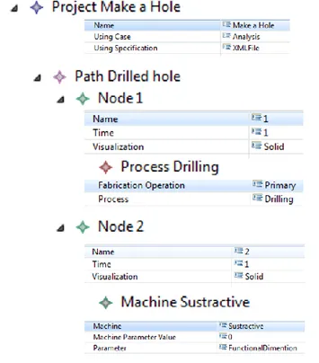
The instantiation of the model for this case, is represented in the next arborescence structure; where the different characters are defined (see Figure 9). Once the first conditions are given, the data model is compared in the knowledge base created in the
TEEXMA software. As presented in the knowledge model, the data in each node is analyzed. The information given, based on the three axis, is compared against the inner parameters (of the perspective, the visualization and the time) and the existing relations (as the process/machine, process/part, process/tool and process/material).
Figure 9 Structure arborescence for the drilling process in the data model
Initially, the process is known, but not the parameters related to it. In this case, the system take the required parameters from the knowledge base and give back to the designer. Parameters as the cutting deep, the drilled diameter, the cutting speed and others are proposed. Due to the relations stablished inside the knowledge model (as the established between the process and the part) the cutting diameter and the drilled diameter can be associated, assigning the corresponding values and characteristics. As well, in other levels inside of the relation, aspects as the diameter required for the hole are associated to the effect produced during the drilling, given other parameter to define. Aside the diameter, the same is applied to the deepness, where the length value and the geometrical characteristic define the partial shape.
Link to the different visualizations levels, the physical aspects establish different characteristics. This can be associated to the drilling process, in particular in the material removal. In a general level,
the model can be represented in a cylindrical configuration, letting the proposed shape (see Figure
10a). One added value to this model, if we going
closer (more detailed level of visualization) can be visualized future aspects. In this case, for the layer level there is no difference with the solid scale. Nevertheless, the trajectory and the punctual exist. In particular, regarding to the drilling at lower views the effects of the material removed are considered. This establish a helicoid as part of the trajectory that the material is taking out (for the trajectory level, see
Figure 10b) and more detail effect of the material
brake and possible roughness (for the punctual level, see Figure 10c).
Figure 10 Visualization of the manufacture surfaces for a drilling process
This generate the new nodes to analyze and detail more the aspects in the study case. Until this point, the parts required and the process selected were evaluated; now, the other perspectives needs to be evaluated. In this case, the possibilities left are the machine, the tool and the material. Taken into consideration that one of the main requirements is the machine, the next node is denoted as N4.
• Node 4 (N4): Time: As DFM1; Visualization: Solid; Perspective: Machine (tuning machine)
The node 4 is the result of the previous evaluation compared with the aspects on N2 but in a different time.
In this, the aspects that compose the node 4 are compared with the knowledge model. Taken the information relative to the machine in the knowledge base, particular processing conditions are needed. For this reason: the model requires to be reoriented in the horizontal direction (technological approach); the dimension of the part will be limited to the volume and the plane of action (physical approach); the point of entry is in the center of the part (technological approach), among other aspects, as seen in Figure
11. As shown, aspects as the orientation and the entry
point can’t be modified, for that reason, the system will provide them as limits. But in some cases as for the volume, the designer can manage the shape. Taken the node 4 and the parameters of the machine, the new characteristics are given; and the possible parameters to modify for the designer are proposed.
Figure 11 Turning machine aspects
This are shown in the data model regarding to the parameters related to the machine, in this case for the physical approach. As result, the new proposed model are presented (as see in the Figure 12)
Figure 12 Reorientation of the manufactured surfaces
The frontal area of the part is based on the characteristics and the shape that the piece could hold the machine. In this sense, the geometrical characteristic, manufacture surfaces, manufacture trajectories, etc., taken from the knowledge base can be proposed (i.e. physical limits based on the type of claws used to hold the part). To model this case, the example was based in a cylindrical shape with 15 mm of diameter (as show in the Figure 13).
Figure 13 Drilling surface against the functional volume of the machine
The selection is taken and the system reevaluates in the knowledge base if some parameters are not valid (diameter over the limits of the machine or diameters lesser than the diameter of design). Once everything is verified, the new nodes N5 and N6 are generated with the new data. To finish the last perspectives (the material and the tool) the node N4 can take two paths, one for each missing aspect. The selection and evaluation of one or the other could generated the same result or different; this can cause an increasing in the designing times.
To complete the model, the next aspect evaluated was the tool. In this case, the same procedure as before is followed, and the system evaluate the possible relation of the node with it. In this, the properties of the tool are taken (diameter of the tool, cut section, tip geometry, length of the tool; materials that can process, etc.) and related to the part, the machine and the process (i.e. hole dimension, holding points, cut effects). The comparison, as for the dimensional values (hole diameter against tool diameter), provide the new result and the new model. As result, the tool required needs to have 5mm of diameter, with a length over the 30mm. The proposed tool will be retrieved from the catalog of tools provided on the knowledge base. As previous cases, the knowledge base will provide the parameters required to be selected by the designer in the data model, in the tool section.
Selected the tool from the possibilities, the values are evaluated again. In this particular case, one limit associated to the tool comes out. Due to the drilling process is made to a part longer than 5 times the diameter of the tool, the manufacturing procedure require to be realized in two movements. The first will remove part of the material (under the limit), and the second will done to make the through hole. This
consideration is due to the technological approach proposed in the different relations. In particular for this case, as was establish before, in the layer visualization was not present any model, but due to this, the manufacture surface is divided in two stages, that could represent or affect the general representation and information necessary to implement in the model. As result the manufacture phases will be represented as in the Figure 14.
Figure 14 New manufacture surfaces
The knowledge provided shown a better and more complex aspect in the details of the final model, allowing to add more information and data that could modify the final result. One time is selected the model, a new node is generated, N7, where the perspectives of the part, machine, process and tool will be cover. To finish, the last perspective, the material, is evaluated as the others in the previous cases. In this, the perspectives are compared between them, and the possible inconvenient where adjusted to guarantee a product design for manufacture. In this case, two considerations are establish, the first is regarding the relation material/tool and the second is regarding to the material/machine.
In the first, the velocity proposed works for materials as the bronze, the cast iron and the meld steel, narrowing the possibilities of design. If other material is proposed after, the knowledge base provide this information, the system will show an error, requiring the modification of the feed rate (i.e. if the design is going to be in tool steel the velocity needs to be reduced). The effects of the chip and the
behavior of the material can be seen a lower levels. Where characteristics, as the plasticity of the aluminum during the drilling will represent a considerable effect on the life time of the tool. In the second, the dimensions given for the part hold by the machine (as shown in the
Figure 13) is lower than the possible gamma of
rough materials available. For this, is necessary to make another operation to obtain the required results. Taken the steel as the processed material, the information regarding the gamma of products for the steel will be show it, and then the lowest bar with the minimum diameter is going to be selected (approx. 20mm), as can be seen in the Figure 15.
Figure 15 Comparison of volume and surfaces among the material, the machine and the part
In this case, the second operation will not be realized. For this, the external diameter needs to be compared again with all the previous condition. As result, the final decision needs to be modified regarding the feed velocity; decreasing the value (to 60 m/min). Base on the other, the result fits. For last, the last node N8 comprehend all the final results (see Figure
16).
Figure 16 Final result for the drilled part Based on all this, the final path will be structured for the evolution of the nodes N1, N4, N5 and N7
5.
CONCLUSION AND
RECOMMENDATION FOR FUTURE
WORKS
The Multi-scale representation constitutes a promising methodology to allow analysis of complex knowledge, information and data in order to manage them. At the same time, it provides a visualization of the different aspects involved in the design and the manufacturing environment. This approach avoids possible information and data overlapping and overload, concerning to the physical characteristics and the relevant aspects related to the product. Then, the most representative views or the most important relationship are defined so that the product fits better to what is needed. The future perspectives focus on the implementation of the model for the knowledge capitalization and reusing. In this way, the knowledge base and the multi-scale model will be implemented simultaneously, providing progressively the requirements and limitations all along the design phase.
REFERENCES
[1] Umeda Y., Takata S., et al. “Toward integrated product and process life cycle planning—An environmental perspective” CIRP Annals - Manufacturing Technology vol. 61 (2012) p.p. 681– 702
[2] Boothroyd G. “Design for X: Design for Manufacture and Assembly: The Boothroyd-Dewhurst Experience” Marcel Dekker, Inc., NY – USA 2002
[3] Milton N. R. “Knowledge Technologies” 3rd Edition, Editorial Polimetrica, Monza (Milan) – Italy, 2008. [4] Al-Ashaab A., Molyneaux M., Doultsinou, A.,
Brunner B., Martínez E. “Knowledge-based environment to support product design validation” Knowledge-Based Systems, vol. 26 (2012) p.p. 48– 60
[5] Bralia J. G. “Design For Manufacturability Handbook” Ed. McGraw-Hill, 1998.
[6] Monticolo D., Mihaita S., Darwich H., Hilaire V., “An agent-based system to build project memories during engineering projects” Knowledge-Based Systems, vol. 68 (2014) p.p. 88–102
[7] Sánchez-Pi N., Carbó J., Molina J. M. “A knowledge-based system approach for a context-aware system” Knowledge-Based Systems, vol. 27 (2012) p.p. 1–17
[8] Liu D-R, Lin C-W, “Modeling the knowledge-flow view for collaborative knowledge support”
Knowledge-Based Systems vol. 31 (2012) p.p. 41– 54.
[9] Pareige P. “Irradiation effects in structural components of nuclear reactor: an experimental nanoscale point of view” Colloque National MECAMAT - Aussois 2013 dans
http://mecamat2013.lmgc.univ-montp2.fr/presentations.htm.
[10] Weinan E. “Principles of Multiscale Modeling”, (2011) p.p. 1-17
[11] Laukkanen A., Holmberg K. , Wallin K., “Multiscale modelling of engineering materials”, Multiscale modelling and design for engineering application at VTT (2013) Finland p.p. 10-18.
[12] Hoque A.S.M., Halder P.K., Parvez M.S., Szecsi T., “Integrated manufacturing features and Design-for-manufacture guidelines for reducing product cost under CAD/CAM environment” Computers & Industrial Engineering 66 (2013) 988–1003
[13] Elliot J.A., “Introduction to Multiscale Modelling of Materials”, Multiscale Modelling Methods for Applications in Materials Science vol 19, p.p. 1-20 [14] Liu W.K., Qian D., Gonella S., Li S., Chen W.,
Chirputkar S., “Multiscale methods for mechanical science of complex materials: Bridging from quantum to stochastic multiresolution continuum” International journal for numerical methods in engineering.
[15] Horstemeyer M., “Multiscale Modeling: A Review” Practical Aspects of Computational Chemistry, ed. J. Leszczynski and M.K. Shukla, Springer Science+Business Media, pp. 87-135, 2009.
[16] Revuelta A.,“Vertical multiscale modelling” Multiscale modelling and design for engineering application at VTT (2013) Finland p.p. 10-18. [17] Kendall S.L., Creen M., “An Introduction to
Knowledge Engineering”, Springer-Verlag, London 2007.
[18] Cunningham, J. J., Dixon, J. R., (1988), "Designing with Features: The Origin of Features"; Proceedings ASME International Computers in Engineering Conference, Vol. 1, San Diego, pp. 237-243.
[19] Horváth, I., Kulcsár, P., and Thernesz, V., 1994, "A Uniform Approach to Handling of Feature-Objects in an Advanced CAD System", in: Advances in Design Automation, DE-Vol. 69-1, ed. by Gilmore, B. J., Hoeltzel, D. A., Dutta, D., Eschenaurer, H. A., ASME, New York, pp. 547-562.

![Figure 2 Composition of the working environment [9].](https://thumb-eu.123doks.com/thumbv2/123doknet/7374050.214954/4.892.92.444.867.1139/figure-composition-working-environment.webp)