Publisher’s version / Version de l'éditeur:
Vous avez des questions? Nous pouvons vous aider. Pour communiquer directement avec un auteur, consultez la Questions? Contact the NRC Publications Archive team at
[email protected]. If you wish to email the authors directly, please see the first page of the publication for their contact information.
https://publications-cnrc.canada.ca/fra/droits
L’accès à ce site Web et l’utilisation de son contenu sont assujettis aux conditions présentées dans le site LISEZ CES CONDITIONS ATTENTIVEMENT AVANT D’UTILISER CE SITE WEB.
Research Report (National Research Council of Canada. Construction), 2017-12
READ THESE TERMS AND CONDITIONS CAREFULLY BEFORE USING THIS WEBSITE.
https://nrc-publications.canada.ca/eng/copyright
NRC Publications Archive Record / Notice des Archives des publications du CNRC :
https://nrc-publications.canada.ca/eng/view/object/?id=164f4400-f3d5-491b-909d-d66c61774060 https://publications-cnrc.canada.ca/fra/voir/objet/?id=164f4400-f3d5-491b-909d-d66c61774060
NRC Publications Archive
Archives des publications du CNRC
For the publisher’s version, please access the DOI link below./ Pour consulter la version de l’éditeur, utilisez le lien DOI ci-dessous.
https://doi.org/10.4224/23002820
Access and use of this website and the material on it are subject to the Terms and Conditions set forth at
Apparent sound insulation in wood-framed buildings
RR-336
Apparent Sound Insulation
in Wood-Framed Buildings
Christoph Hoeller, David Quirt, Markus Mueller-Trapet
December 2017
Scope
This Report presents the results from substantial experimental studies of sound transmission, together with an explanation of calculation procedures to predict the sound transmission between adjacent spaces in a building with wood-framed walls and floors.
This Report presents two types of experimental data for wood-framed constructions:
Test data for direct sound transmission through typical framed wall assemblies and wood-framed floor assemblies, plus a summary of trends for such constructions and references to compilations of additional data
Test data for flanking sound transmission measured following the procedures of ISO 10848 for coupled wall/floor junctions and wall/wall junctions
Worked examples for calculating the apparent sound transmission class (ASTC) rating between adjacent dwelling units are presented to illustrate how the experimental data can be applied.
Acknowledgments
The research studies on which this Report is based were supported by the Canadian Wood Council and a variety of other industry partners whose participation is recognized in the research reports referenced in the Appendix. The development of this Report was supported by the Canadian Wood Council. The financial support is gratefully acknowledged.
Disclaimer
Although it is not repeated at every step of this Report, it should be understood that some variation in sound insulation is to be expected in practice due to changes in the specific design details, quality of workmanship, su stitutio of ge e i e ui ale ts , or simply rebuilding the construction. It would be prudent to allow a margin of error of 2-3 ASTC points to ensure that a design will satisfy a specific requirement.
Despite this caveat, the authors believe that methods and results shown here do provide a good estimate of the apparent sound insulation for the types of constructions presented.
Contents
1 Sound Transmission via Many Paths ...1
1.1 Predicting Sound Transmission in a Building ... 3
1.2 Standard Scenario for Examples in this Report ... 4
1.3 Applying the Concepts of ISO Standards in an ASTM Environment ... 6
1.4 Combining Sound Transmitted via Many Paths ... 8
2 Sound Transmission through Wood-Framed Walls and Floors ... 11
2.1 Coding System for Specimen Descriptions ... 13
2.2 Wall Assemblies Framed with 1 Row of Wood Studs ... 15
2.3 Wall Assemblies Framed with 2 Rows of Wood Studs ... 19
2.4 Wall Assemblies for Wood-Framed Mid-Rise Buildings ... 23
2.5 Floor/Ceiling Assemblies with Wood Framing ... 31
2.6 Summary for Chapter 2: Sound Transmission through Wood-Framed Walls and Floors ... 38
3 Flanking Sound Transmission in Wood-Framed Constructions ... 39
3.1 Test Facilities and Test Procedures for Wood-Framed Assemblies ... 39
3.2 Wall/Floor Junctions for Low-Rise Buildings – Wall Assemblies with 1 Row of Wood Studs ... 44
3.3 Wall/Floor Junctions for Low-Rise Buildings – Wall Assemblies with 2 Rows of Wood Studs ... 90
3.4 Wall/Wall Junctions for Low-Rise Buildings – Wall Assemblies with 1 Row of Wood Studs ... 98
3.5 Wall/Wall Junctions for Low-Rise Buildings – Wall Assemblies with 2 Rows of Wood Studs ... 103
3.6 Wall/Floor Junctions for Mid-Rise Buildings – Wall Assemblies with Staggered Wood Studs ... 106
3.7 Wall/Wall Junctions for Mid-Rise Buildings – Wall Assemblies with Staggered Wood Studs ... 120
3.8 Summary for Chapter 3: Flanking Sound Transmission in Wood-Framed Constructions ... 124
4 Predicting Sound Transmission in Wood-Framed Buildings ... 125
4.1 Calculation Procedure for Wood-Framed Walls and Floors ... 127
4.2 Examples for Low-Rise Buildings – Wall Assemblies with 1 Row of Wood Studs ... 133
4.3 Examples for Low-Rise Buildings – Wall Assemblies with 2 Rows of Wood Studs ... 145
4.4 Examples for Mid-Rise Buildings – Wall Assemblies with Staggered Wood Studs ... 155
Chapter 1: Sound Transmission via Many Paths
1 Sound Transmission via Many Paths
The simplest approach to sound transmission between adjacent rooms in buildings considers only the sound transmission through the separating wall or floor. This perspective has been entrenched in North American building codes, which for many decades have considered only the ratings for the separating assembly: sound transmission class (STC) or field sound transmission class (FSTC) for airborne sources and impact insulation class (IIC) for footstep noise.
Implicit in this approach (illustrated in Figure 1.1) is the simplistic assumption that sound is transmitted only through the obvious separating assembly – the separating wall assembly when the rooms are side-by-side, or the floor/ceiling assembly when rooms are one-above-the-other. If the sound insulation is inadequate, this is attributed to errors in either the design of the separating assembly or the workmanship of those who built it, and remediation focusses on that assembly. Unfortunately, this paradigm is still common among designers and builders in North America.
Figure 1.1: The drawings in Figure 1.1 and 1.2 show
a cross-section through a building with two adjacent rooms. Part of the sound from an airborne source in one unit (represented by the red loudspeaker in the drawings, which could include anything from a home theatre to people talking loudly) is transmitted to the adjacent unit. The historic approach, illustrated in Figure 1.1, considers only the direct sound transmission through the separating assembly.
Figure 1.2: In reality, there are many paths for
sound transmission between adjacent rooms, including both direct transmission through the separating assembly and indirect structure-borne paths, a few of which are indicated here (see Section 1.4 for more detail). The structure-borne paths usually significantly affect the overall sound transmission.
In reality, the technical issue is more complex, as illustrated in Figure 1.2. There is direct transmission of sound through the separating assembly, but that is only part of the story of how sound is transmitted between adjacent rooms. As shown in the figure, the airborne sound source excites all the surfaces in the source space and all of these surfaces vibrate in response. Some of this vibrational energy is transmitted as structure-borne sound across the surfaces abutting the separating assembly, through the junctions where these surfaces join the separating assembly, and into surfaces of the adjoining space. These surfaces in the receiving room then radiate part of the vibrational energy as airborne sound. The sound transmission by these paths is called flanking sound transmission.
Transmission through wall Airborne Sound Source Separating assembly Transmission through wall Airborne Sound Source Separating assembly Flanking Transmission via ceiling surfaces Transmission through wall Airborne Sound Source Flanking Transmission via floor surfaces Flanking Transmission
via ceiling surfaces Transmission through wall Airborne Sound Source Flanking Transmission via floor surfaces
Chapter 1: Sound Transmission via Many Paths
It follows that the sound insulation between adjacent rooms is always worse than the sound insulation provided by the obvious separating assembly. Occupants of the adjacent room actually hear the combination of sound due to direct transmission through the separating assembly plus sound due to structure-borne flanking sound transmission involving all the other elements coupled to the separating assembly. Furthermore, there is also transmission of sound through leaks (openings) in the walls. The importance of including all of the transmission paths has long been recognized in principle (and the fundamental science was largely explaineddecades ago, by Cremer et al. [8]). The challenge has been to reduce the complicated calculation process to manageable engineering that yields trustworthy quantitative estimates, and to standardize that process to facilitate its inclusion in a regulatory framework.
For design or regulation, there is well-established terminology to describe the overall sound transmission including all paths between adjacent rooms. ISO ratings such as the weighted apparent sound reduction i de R’w) have been used in many countries for decades, and ASTM E336 defines the corresponding apparent sound transmission class (ASTC), which is used in the examples in this Report. Although measuring the ASTC in a building (following ASTM Standard E336) is quite straightforward, predicting the ASTC due to the set of transmission paths in a building is more complex. However, standardized frameworks for calculating the overall sound transmission have been developed. These start from standardized measurements to characterize sub-assemblies, and have been used for more than a decade to support performance-based European code systems.
In 2005, ISO published a calculation method, ISO 15712- , Buildi g a ousti s — Estimation of acoustic performance of buildings from the performance of elements — Part 1: Airborne sound insulation et ee oo s . This is o e pa t of a se ies of sta da ds: Pa t deals ith impact sound insulation between rooms , Pa t deals ith ai o e sou d i sulatio agai st outdoo sou d , a d Pa t deals
ith transmission of indoor sound to the outside .
There are two significant impediments to applying the methods of ISO 15712-1 in a North American context:
ISO 15712-1 provides very reliable estimates for buildings constructed from heavy, homogeneous building elements, but not for buildings constructed from lightweight (steel- or wood-) framed elements widely used in North America.
ISO standards for building acoustics have many differences from the ASTM standards used by the construction industry in North America – both in their terminology and in specific technical requirements for measurement procedures and ratings.
The following sections of this chapter outline a strategy for dealing with these limitations, both explaining how to merge ASTM and ISO test data and procedures, and providing recommendations for adapting the calculation procedures for wood-framed constructions.
Chapter 1: Sound Transmission via Many Paths
This Report was developed in a project established by the National Research Council Canada and the Canadian Wood Council to support the transition of construction industry practice to using ASTC rather than STC for sound control objectives in the National Building Code of Canada (NBCC). However, the potential range of application goes beyond the minimum requirements of the NBCC. The Report also facilitates design to provide enhanced levels of sound insulation, and should be generally applicable to construction with wood-framed assemblies in both Canada and the USA.
1.1 Predicting Sound Transmission in a Building
As noted above, ISO 15712-1 provides reliable estimates of apparent sound transmission for buildings constructed from heavy, homogeneous building elements, but it is less accurate for some other common types of construction, especially for lightweight wood-framed and steel-framed constructions. ISO 15712-1 has other limitations, too. For example, in several places the Standard identifies situations (especially for lightweight framed construction) where the detailed calculation is not appropriate. However, the Standard does not provide specific guidance on how to deal with such cases. Many of these limitations can be overcome by using data from laboratory testing according to the ISO 10848 series of standards that were developed to deal with measuring flanking sound transmission for various combinations of construction types and junctions. Because the current (2005) edition of ISO 15712-1 replicates a European standard developed before 2000, it does not reference more recent standards such as the ISO 10848 series, or the ISO 10140 series that are replacing the ISO 140 series referenced in ISO 15712-1. The 2015 edition of the National Building Code of Canada deals with this problem by specifying suitable procedures and test data to deal with calculating ASTC for different types of construction. These procedures are also explained in the NRC Research Report RR- , Guide to Cal ulati g Ai o e “ou d T a s issio i Buildi gs [13].
For wood-framed constructions1, the calculation procedure of ISO 15712-1 (both the Detailed Method and the Simplified Method) must be modified to obtain accurate results. This Report outlines the steps of the calculation process and the standard measurement data required for such calculations. These modifications are consistent with the requirements in the 2015 National Building Code of Canada. This Report is restricted to consideration of buildings where all wall and floor assemblies are framed with wood studs or wood joists5. The scope could be expanded to include the combination of wood-framed assemblies with other construction types. Sound transmission data for wood-wood-framed floors connected to masonry concrete block walls is provided in the NRC Research Report RR- , Appa e t Sound I sulatio i Co ete Blo k Buildi gs [15.2].
In order to respect copyright, the Report does not reproduce the equations of ISO 15712-1, but it does indicate which equations apply in each context and provides key adaptations of the ISO expressions needed to apply the concepts in an ASTM context.
1
Chapter 1: Sound Transmission via Many Paths
1.2 Standard Scenario for Examples in this Report
The prediction of the sound transmitted in buildings depends not only on the construction details of the transmission paths, but also on the size and shape of each of the room surfaces and on the sound absorption in the receiving room. The ability to adjust the calculation to fit the dimensions in a specific building or to normalize to different receiving room conditions enables a skilled designer to obtain more accurate predictions.
However, for purposes of this Report where results will be presented for a variety of constructions, easy and meaningful comparison of results is facilitated by calculating all the examples for a common set of room geometry and dimensions. This is particularly useful where only small changes are made between the construction details in the examples, since any change in the ASTC rating can then be attributed to the changes which were made in the construction details.
Therefore, a Standard Scenario has been adopted for all the examples, with the following constraints: Sound is transmitted between adjacent rooms, either side-by-side or one-above-the-other. The adjacent rooms are mirror images of each other, (with one side of the separating assembly
facing each room, and constituting one complete face of each rectangular room).
The Standard Scenario is illustrated in Figures 1.3 and 1.4, for the cases where one room is beside the other, or one is above the other, respectively.
Figure 1.3:
Standard Scenario for the ho izo tal room pai case where the pair of rooms are side-by-side with a separating wall assembly between the two rooms.
Chapter 1: Sound Transmission via Many Paths
Figure 1.4:
Standard Scenario for the e ti al room pai case where one of the pair of rooms is above the other, with the floor/ceiling assembly between the two rooms.
The pertinent dimensions and junction details are shown in Figures 1.3 and 1.4.
Note the labelling of junctions at the four edges of the separating assembly (J1 to J4) in Figures 1.3 and 1.4. These junction designations are used in the design examples throughout this Report. For horizontal room pairs (i.e. rooms are side-by-side) the separating wall is 2.5 m high by 5 m wide,
flanking floor/ceilings are 4 m by 5 m, and flanking walls are 2.5 m high by 4 m wide.
For vertical room pairs (i.e. one room is above the other) the separating floor/ceiling is 4 m by 5 m wide and flanking walls in both rooms are 2.5 m high.
In general, it is assumed that junctions at one side of the room (at the separating wall if rooms are side-by-side) are cross-junctions, while one or both of the other two junctions are T-junctions. This enables the examples to illustrate typical differences between the two common junction cases. For a horizontal pair, the separating wall has T-junctions with the flanking walls at both the façade
and corridor sides, and cross-junctions at floor and ceiling.
For a vertical pair, the façade wall has a T-junction with the separating floor, but the opposing corridor wall has a cross-junction, as do the other two walls.
Deviations from the Standard Scenario, such as room pairs where one room is an end unit with T-junctions instead of cross-T-junctions, can be calculated by substituting the appropriate junction details in the calculation procedures and in the worked examples in this Report.
Chapter 1: Sound Transmission via Many Paths
1.3 Applying the Concepts of ISO Standards in an ASTM Environment
Although the building acoustics standards developed by ASTM are very similar in concept to the corresponding ISO standards, there are differences in the terminology and technical requirements between the two that present numerous barriers to using a mix of standards from the two domains. Although ASTM standard E336 recognizes the contribution of flanking to apparent sound transmission, there is neither an ASTM standard for measuring the structure-borne flanking sound transmission that often dominates sound transmission between rooms, nor an ASTM counterpart of ISO 15712-1 for predicting the combination of direct and flanking sound transmission. In the absence of suitable ASTM standards, this Report uses the procedures of ISO 15712-1 and data from the complementary ISO 10848 series, but connects this ISO calculation framework to the ASTM terms and test data widely used by the North American construction industry. This methodology combines identifying where data from ASTM laboratory tests can reasonably be used in place of their ISO counterparts, and presenting the results using ASTM terminology (or new terminology for flanking sound transmission that is consistent with existing ASTM terms) to facilitate their use and understanding by a North American audience. Some obvious counterparts in the terminology are presented in Table 1.1.
ISO Designation Description ASTM Counterpart
ISO 10140 Parts 1 and 2 (formerly ISO 140-3)
Laboratory measurement of airborne sound transmission through a wall or floor
ASTM E90
sound reduction index, R (from ISO 10140-2)
Fraction of sound power transmitted (in dB) at each frequency, in laboratory test
sound transmission loss, TL (ASTM E90) weighted sound reduction
index, Rw (ISO 717-1)
Single-number rating determined from R or TL values in standard frequency bands
sound transmission class, STC (ASTM E413) apparent sound reduction
index, R’ (ISO 16283-1)
Fraction of sound power transmitted (in dB) at each frequency, including all paths in a building
apparent sound transmission loss,
ATL (ASTM E336) weighted apparent sound
reduction index, R’w (ISO 717-1)
Single-number rating determined from R’ or ATL values in standard frequency bands
apparent sound transmission class, ASTC
(ASTM E413)
Table 1.1: Standards and terms used in ISO 15712-1 for which ASTM has close counterparts
Note that the des iptio ou te pa t does ot i pl that the A“TM a d I“O sta da ds o te s a e exactly equivalent. RW and STC are not interchangeable. Neithe a e R’W and ASTC because of systematic differences in the calculation procedures. However, the laboratory test used to measure airborne sound transmission through wall or floor assemblies – ASTM E90 and its counterpart ISO 10140-2 – are based on essentially the same procedure, with minor variants in facility requirements. Therefore, the easu ed ua tities sou d t a s issio loss f o the A“TM E test a d sou d edu tio i de
Chapter 1: Sound Transmission via Many Paths
data from ISO 10140-2 tests in the calculations of ISO 15712-1 to obtain a sensible answer. Similarly, the simplified calculation of ISO 15712-1 may be performed using STC ratings to predict the ASTC rating. The close parallel between sou d edu tio i de a d sou d t a s issio loss also ea s that esults from ISO 15712-1 calculations o all e p essed as R’ alues a o fide tl e t eated as al ulated apparent sound transmission loss (ATL) values and then used in the procedure of ASTM E413 to calculate the ASTC rating, which is the objective for designers or regulators in the North American context.
For purposes of this Report, a glossary of new terms with counterparts in ISO 15712-1 (using terminology consistent with measures used in ASTM standards) and of other key terms from pertinent ISO standards such as ISO 15712-1 and ISO 10848 is presented in Table 1.2.
In addition, several scientific terms used in ISO 15712-1 at various stages of the calculation have been used without change. These include: radiation efficiency, internal loss factor, total loss factor, equivalent absorption length, and transmission factor. They are described in the glossary in Annex A of ISO 15712-1.
Terms used in this Report Description
Structural reverberation time (TS)
Structural reverberation time is a measure indicating the rate of decay of vibration energy in an element and can apply either to a laboratory wall or floor specimen, or to a wall or floor assembly in-situ in a building. Transmission loss in-situ
(TLsitu)
Transmission loss situ is the counterpart of sound reduction index in-situ (Rsitu) described in ISO 15712-1 as "the sound reduction index of an element in the actual field situation".
Flanking sound transmission loss (Flanking TLij)
Flanking sound transmission loss is the counterpart of flanking sound reduction index (Rij) in ISO 15712-1. It is a measure of sound transmission via the flanking path from element i in the source room to element j in the receiving room, normalized like apparent sound transmission loss, as described in Section 1.4.
Flanking sound transmission class (Flanking STCij)
Flanking STC is the single-number rating calculated from the flanking sound transmission loss following the STC calculation procedure of ASTM E413.
Table 1.2: Key terms used in this Report to deal with concepts from ISO 15712-1 and ISO 10848 for
Chapter 1: Sound Transmission via Many Paths
1.4 Combining Sound Transmitted via Many Paths
The calculations of ISO 15712-1 must deal with combining the sound power transmitted via the direct path and via a set of flanking paths. To keep track of the sound transmission paths, it is useful to introduce the labeling convention for the paths that is used in ISO 15712-1. It is shown in Figure 1.5.
Figure 1.5: This figure shows the labelling
convention for transmission paths used in ISO 15712-1. Consider the transmission of airborne sound from a source room (left) to a receiving room (right). Each transmission path involves one surface in the source room (denoted by a capital letter) and one in the receiving room (denoted by a lower case letter). Direct transmission through the separating assembly is path Dd. For each edge of the separating assembly there are three flanking paths: Ff from flanking surface F to flanking surface f, Df from direct surface D to flanking surface f, and Fd from flanking surface F to direct surface d.
Note that the lette F o f de otes fla ki g su fa e, a d D o d de otes the su fa e fo direct transmission, i.e. the surface of the separating assembly. These surfaces may be either wall or floor/ceiling assemblies.
The labels for the flanking surfaces of the Standard Scenarios are detailed in the following Table 1.3.
Room Pair Surfaces D and d Flanking Surfaces F and f Junction
Horizontal
(Fig. 1.3) Separating wall
Junction 1: floor F and f Junction 2: façade wall F and f Junction 3: ceiling F and f Junction 4: corridor wall F and f
Cross-junction T-junction Cross-junction T-junction
Vertical
(Fig. 1.4) Separating floor/ceiling
Junction 1: wall F and f
Junction 2: façade wall F and f Junction 3: wall F and f
Junction 4: corridor wall F and f
Cross-junction T-junction Cross-junction Cross-junction
Chapter 1: Sound Transmission via Many Paths
In Canada, building elements are normally tested according to the ASTM E90 standard, and building code requirements are given in terms of apparent sound transmission class (ASTC) determined from the apparent sound transmission loss (ATL) for the set of frequency bands from 125 Hz to 4000 Hz, following the procedure in ASTM E413. Merging this context with using the ISO 15712-1 procedures in this Report, the te s di e t sound t a s issio loss a d fla ki g sound t a s issio loss ha e ee introduced to provide consistency with ASTM terminology while matching the function of the direct and flanking sound reduction indices defined in ISO 15712-1.
Section 4.1 of ISO 15712-1 defines a process to calculate the apparent sound transmission by combining the sound power transmitted via the direct path and the twelve first-order flanking paths (3 at each edge of the separating assembly, as illustrated in Figure 1.5). Equation 14 in ISO 15712-1 is recast here with slightly different grouping of the paths (treating the set of paths at each edge of the separating assembly in turn) to match the presentation approach chosen for the examples in this Report.
The apparent sound transmission loss (ATL) between two rooms (assuming the room geometry of Section 1.2 and neglecting sound that is by-passing the building structure, for example sound transmitted through leaks and ducts) is the resultant of the direct sound transmission loss (TL ) through the separating wall or floor element and the set of flanking sound transmission loss contributions of the three flanking paths (TL� ,TL� , and TL ) for each junction at the four edges of the separating element as shown in Figure 1.5:
� � = − ∙ log − . ∙ ���+ ∑ ( − . ∙ ���+ − . ∙ ��� + − . ∙ ���)
4 =
Eq. 1.1
Note that this equation differs slightly from the calculation of the apparent sound transmission defined in Equation 14 of ISO 15712-1. Equation 1.1 of this Report treats the set of paths at each edge of the separating assembly in turn to match the presentation for the examples in this Report. Equation 1.1 is universally valid for all building systems, and the remaining challenge is to find the right expressions to calculate the path transmission for the chosen building system and situation.
Each of the flanking sound transmission loss values for a specific path is normalized like the apparent sound transmission loss, and can be considered as the ATL that would be observed if only this single path were contributing to the sound transmitted into the receiving room. Normalization of direct and flanking sound transmission input data so that the receiving room absorption is numerically equal to the area of the separating assembly (i.e. using apparent sound transmission loss and ASTC as the measure of system performance) requires suitable corrections to data calculated according to ISO 15712-1, or values of flanking sound transmission loss from laboratory testing according to ISO 10848, so that the set of path transmission loss values can be properly combined or compared. This normalization process is fully described in the calculation procedures in Chapter 4.
Chapter 1: Sound Transmission via Many Paths
The standard ISO 15712-1 describes two methods of calculating the apparent sound insulation in a building: the Detailed Method and the Simplified Method. This Report describes the Simplified Method to calculate the apparent sound insulation in a building consisting of wood-framed elements. The Simplified Method uses the single-number ratings (STC or Flanking STC for each transmission path) instead of the frequency-dependent transmission loss values and yields the ASTC directly:
� = − ∙ log [ − . ⋅ ��+ ∑4 ( − . ⋅ ��+ − . ⋅ ��+ − . ⋅ ��)
= ] Eq. 1.2
The Simplified Method has been widely used by designers in Europe for many years for calculations based on RW data. Its primary advantage is the simplicity of the procedure, which makes it usable by non-specialists, as illustrated by the worked examples in Section 4.2. Although it is less rigorous than the Detailed Method, the differences between the results using the two methods are small, and the calculations for the Simplified Method use approximations that should ensure the results are slightly conservative.
Cautions and limitations to examples presented in this Report:
This Report was developed to support the transition to ASTC ratings for sound control objectives in the National Building Code of Canada. Simplifications were made to meet the specific needs of that application, where sound insulation is addressed only in the context of multi-unit residential buildings. The simplifications include that:
Transmission around or through the separating assembly due to leaks at its perimeter or penetrations such as ventilation systems are assumed negligible
.
Indirect airborne transmission (for example airborne flanking via an unblocked attic or crawl space) is assumed to be suppressed by normal fire blocking requirements.
For adjacent occupancies in a multi-family residential building, these two issues should be dealt with by normal good practice for fire and sound control between adjoining dwellings.
If this Report is applied to situations other than separation between adjacent units in multi-family residential buildings, some of these issues may have to be explicitly addressed in the calculation process. For example, for adjoining rooms within a single office or home, flanking paths such as ventilation ducts or open shared plenum spaces may be an issue. The flanking sound transmission associated with these additional paths should be determined and included in the calculated ASTC. ISO 15712-1 includes specific guidance for such issues, and the examples in this Report allow for such a correction.
Chapter 2: Sound Transmission through Wood-Framed Walls and Floors
2 Sound Transmission through Wood-Framed Walls and Floors
This chapter presents the results of direct sound transmission loss tests of wall and floor assemblies with several variants of wood framing. The tested assemblies include assemblies with a variety of framing details and linings covering the surfaces of the wood framing.
ASTM E90 Test Method
Direct sound transmission loss tests of wall and floor assemblies were conducted i NRC’s Wall a d Floo Sound Transmission Facilities according to the ASTM E90 test protocol [1]. Concept drawings of the sound transmission facilities are presented in Figure 2.1.
Figure 2.1: A concept drawing of the Wall
Sound Transmission Facility at the NRC is presented in the upper drawing. The NRC Floor Sound Transmission Facility, shown in the lower drawing, is similar except that one room is above the other.
In both cases, full scale test assemblies are mounted in the massive concrete movable test frames between the two reverberant rooms. The test openings are 3.66 m wide and 2.44 m high for walls and 4.70 m by 3.78 m for floors.
In the wall facility, the rooms (designated la ge ha e and s all ha e have approximate volumes of 250 m3 and 140 m3 respectively. In the floor facility, both chambers have volumes of approximately 175 m3. All the facility rooms are hard-walled reverberation chambers that are vibration-isolated from each other and from the specimen frame. The rooms have fixed and/or moving diffusor panels to enhance diffusivity of the sound fields.
The facilities (including instrumentation) and the test procedures satisfy or exceed all requirements of ASTM E90.
Chapter 2: Sound Transmission through Wood-Framed Walls and Floors
Each facility is equipped with an automated measurement system for data acquisition and post-processing. In each room, a calibrated Brüel & Kjaer condenser microphone (type 4166 or 4165) with preamp is moved under computer control to nine positions, and measurements are made in both rooms using a National Instruments NI-4472 data acquisition system installed in a computer. Each room has four bi-amped loudspeakers driven by separate amplifiers and noise sources. To increase randomness of the sound field, there are fixed diffusing panels in each room.
Measurements of the direct airborne sound transmission loss (TL) were conducted in accordance with the requirements of ASTM E90-09, “ta da d Method for Laboratory Measurement of Airborne Sound Transmission Loss of Building Pa titio s . The sound transmission loss tests were performed in both directions – from the large chamber to the small chamber and vice-versa for walls, and from the upper chamber to the lower chamber and vice-versa for floors. The results presented in this Report are given as the averages of the two transmission directions to reduce measurement uncertainty due to factors such as calibration errors and local variations in the sound fields.
For every measurement, direct sound transmission loss values were calculated from the average sound pressure levels in the source room and the receiving room and the average reverberation times of the receiving room. One-third octave band sound pressure levels were measured for 32 seconds at nine microphone positions in each room and then averaged to get the average sound pressure level in each room. Five sound decays were averaged to get the reverberation time at each microphone position in the receiving room; these times were averaged to get the average reverberation times for each room. The frequency-dependent direct sound transmission loss was measured in one-third octave bands in the frequency range from 50 Hz to 5000 Hz. However, only the frequency range between 125 Hz and 4000 Hz is considered in the calculation of the sound transmission class (STC) single-number rating in accordance with ASTM E413 [3].
This chapter presents a summary of results in terms of the single-number STC ratings that are required for the calculations in Chapter 4 to determine the ASTC rating. For each type of wall and floor assembly, dependence of the STC on the construction details is discussed in the discussion of trends. The Chapter focuses on wall and floor assemblies that are capable of meeting the sound insulation requirements in the 2015 National Building Code of Canada (ASTC not less than 47), i.e. on wall and floor assemblies with an STC rating of at least 47. Data for wall and floor assemblies with lower STC ratings can be found in the NRC publications referenced in the Appendix [16.2, 16.4, 16.7].
Chapter 2: Sound Transmission through Wood-Framed Walls and Floors
2.1 Coding System for Specimen Descriptions
A coding system is used throughout this Report to minimize long descriptions of floor or wall constructions. Each surface layer in a floor or wall is coded as follows:
An integer representing the number of layers of material - if the number of layers is one, the leading 1 is omitted
A sequence of letters to indicate the material in the layer (see Table 2.1 below) A number representing the thickness in mm of each sheet or element in the layer Underscores separating the codes for each layer
The coding system is also applied to elements that do not constitute surface layers such as joists, studs, and resilient metal channels. For such elements, the number following the letters is the depth of each element (the dimension along the axis perpendicular to the surface of the assembly) and the number in parentheses following the depth code is the separation between adjacent elements.
Table 2.1: Examples of the codes used to identify materials and to describe constructions.
Code Material
CONxx Concrete mm thick
GCONxx Gypsum concrete mm thick GFBxx Glass fibre batts mm thick
MFBxx Mineral or rock fibre batts mm thick CFLxx Blown-in cellulose fibre mm thick PLYxx Plywood mm thick
OSBxx Oriented strandboard mm thick
WJxx(ss) Solid-sawn wood joists with nominal dimensions 38 mm thick and mm deep, spaced ss mm on centre
WIxx(ss) Wood I-joists fabricated from engineered wood products with o i al di e sio s deep, spa ed ss o centre WTxx(ss) Wood trusses ith o i al di e sio s deep, spa ed
ss o e t e
WSxx(ss) Wood studs with nominal dimensions 38 mm thick and deep, spa ed ss o centre
RCxx(ss) Resilie t etal ha els ith o i al depth of , spa ed ss o centre
Chapter 2: Sound Transmission through Wood-Framed Walls and Floors
Note that the coding system is a convenience and actual dimensions may not be exactly as coded. For example, the nominal 16 mm thick gypsum board would be labelled by the manufacturer as 5/8 in. or 15.9 mm thick.
For brevity, not all pertinent parameters are included in the short codes. For example, the weight per unit length or per unit area is not indicated. This information is given wherever pertinent in specimen descriptions in the tables of measurement results and the calculation examples.
Thus the code OSB15_WJ235(400)_GFB150_RC13(600)_2G16 describes a floor with the following construction details:
A 15 mm-thick oriented strandboard (OSB) subfloor
38 mm x 235 mm (2x10) wood floor joists, spaced 400 mm on centre 150 mm-thick glass fibre batts in the cavities between the joists
13 mm-deep resilient metal channels screwed to the bottom of the joists and oriented perpendicular to the joists, spaced 600 mm on centre
Chapter 2: Sound Transmission through Wood-Framed Walls and Floors
2.2 Wall Assemblies Framed with 1 Row of Wood Studs
The focus of this section is the direct sound transmission loss of wall assemblies framed with one row of wood studs with gypsum board attached on both sides of the studs. The gypsum board was fastened directly to the studs or supported on resilient metal channels. Most of the tested assemblies had sound-absorbing material in the cavities between the studs. The typical construction of the wall assemblies described in this Section had a single row of wood studs as shown in Figure 2.2.1.
Figure 2.2.1:
Horizontal cross-section of a wall assembly with a single row of wood studs showing the typical
components. Variations and element properties are listed in more detail on the right.
1. Single row of wood studs1 (with cross-section
38 mm x 89 mm or 38 mm x 140 mm) nominally spaced either 400 mm (16 in.) or 600 mm (24 in.) on centre. 2. Surface of 1 or 2 layers of fire-rated gypsum board2
screwed directly to one face of the wood studs. Gypsum board may be designated either as G13 (nominal thickness of 1/2 in., 12.7 mm) or as G16 (nominal thickness of 5/8 in., 15.9 mm).
3. Sound-absorbing material3
in the cavities between studs may be glass fibre batts (GFB) or mineral fibre batts (MFB) or blown-in cellulose fibre (CFL) approximately filling the cavities.
4. Resilient metal channels, formed from light sheet steel with suitable profile4 andscrewed to the face of the wood studs. Resilient metal channels were spaced either 400 mm (16 in.) or 600 mm (24 in.) on centre. 5. Surface of 1 or 2 layers of fire-rated gypsum board2
screwed to resilient metal channels whose other flange is fastened to the studs. Gypsum board may be designated either as G13 (nominal thickness of 1/2 in., 12.7 mm) or as G16 (nominal thickness of 5/8 in., 15.9 mm).
Drawings are not exactly to scale.
NOTE: For the notes on this page please see the corresponding endnotes on page 166.
NOTE: The tests reported in this section include results from different test series. The year of testing is
coded in the report number for each result. The older tests (1992 to 2005) are documented in the referenced reports and are the basis for the tables of STC ratings in Part 9 of the National Building Code of Canada. Repeated tests indicate that the older results are consistent with newer ones within the expected range of reproducibility for the test method.
Chapter 2: Sound Transmission through Wood-Framed Walls and Floors
Table 2.2.1: STC values for wall assemblies with a single row of wood studs1 with a cross-section of 38 mm x 89 mm (2x4). The results are numbered and organized in groups by common features within each group. All listed assemblies have fire-rated gypsum board, resilient metal channels on one side, and sound-absorbing material essentially filling the cavities between the studs. Some assemblies without sound-absorbing material were tested, but none of those had an STC rating over 48.
Specimen
ID Descriptive Short Code
Reference STC NBCC NRC Test WS89-4a G16_WS89(400)_GFB89_RC13(400,600)_2G16 W4a TL93-118, -120 51 WS89-5a 2G16_WS89(400)_GFB89_RC13(400,600)_G16 W5a 51 WS89-6a 2G16_WS89(400,600)_GFB89_RC13(400)_2G16 W6a TL93-119 55 WS89-4b G16_WS89(600)_GFB89_RC13(400,600)_2G16 W4b TL93-099, -101 54 WS89-5b 2G16_WS89(600)_GFB89_RC13(400,600)_G16 W5b 54 WS89-6b 2G16_WS89(400,600)_GFB89_RC13(600)_2G16 W6b TL93-086, -092 58 WS89-4c G13_WS89(400)_GFB89_RC13(400,600)_2G13 W4c TL93-126, -150, -180, -186 49 WS89-5c 2G13_WS89(400)_GFB89_RC13(400,600)_G13 W5c 49 WS89-6c 2G13_WS89(400)_GFB89_RC13(400,600)_2G13 W6c TL93-127, -151 53 WS89-4d G13_WS89(600)_GFB89_RC13(400,600)_2G13 W4d TL93-97, -99, -101 53 WS89-5d 2G13_WS89(600)_GFB89_RC13(400,600)_G13 W5d 53 WS89-6d 2G13_WS89(400)_GFB89_RC13(600)_2G13 W6d 55 WS89-6e 2G13_WS89(600)_GFB89_RC13(400)_2G13 W6e 55 WS89-6f 2G13_WS89(600)_GFB89_RC13(600)_2G13 W6f TL93-096 58 NOTES:
1. The listed STC values correspond to the values in Table 9.10.3.1. of the 2015 National Building Code of Canada (NBCC).
2. Note that the entries for walls in the W4x and W5x series are for nominal spacing of 400 mm or 600 mm between resilient channels.
3. Results from individual NRC tests scatter around STC values in NBCC Table 9.10.3.1., typically within a range of ±2 points as noted below in the discussion of trends. Some NRC Test References are blank because there is no test corresponding to those specimen details.
4. Entries in the table show GFB (for glass fibre batt), but MFB (mineral or rock fibre batt) or CFL (blown in cellulose fibre) of similar thickness would usually have the same STC rating.
Chapter 2: Sound Transmission through Wood-Framed Walls and Floors
Trends in the Sound Transmission for Wood-Framed Walls with 1 Row of Studs
The effects of key parameters on the sound transmission loss of wood-framed walls with a single row of studs were evaluated by regression analysis. This regression equation was developed as one of the algorithms for a software tool called SOCRATES (for SOund Classification RATing Estimator) [16.9]. The dataset used for the analysis comprised 127 walls constructed using solid wood studs, gypsum board, resilient metal channels, and sound-absorbing material. Parameters varied included:
Type, thickness, and number of layers of gypsum board Type and thickness of the sound-absorbing material Dimensions and spacing of the wood studs
Spacing of the resilient metal channels
The regression analysis yields Equation 2.2.1 for estimating STC ratings:
= . + . [log
+ log
] + .
[
�
ℎ] − .
[�
]
− . [�
]
Eq. 2.2.1 The quality of the fit is indicated in Figure 2.2.2. The significant parameters are: and are the masses per unit area (kg/m2) of the gypsum boards on each face of the wall � ℎ is the distance between the internal faces of the gypsum board in mm
� is the density of the sound-absorbing material in kg/m3
� = / [ _ � � × _ � �], where both spacing values are in m
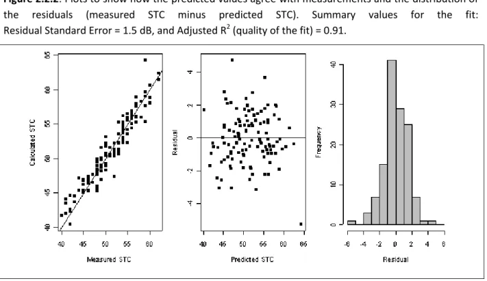
Figure 2.2.2: Plots to show how the predicted values agree with measurements and the distribution of
the residuals (measured STC minus predicted STC). Summary values for the fit: Residual Standard Error = 1.5 dB, and Adjusted R2 (quality of the fit) = 0.91.
Chapter 2: Sound Transmission through Wood-Framed Walls and Floors
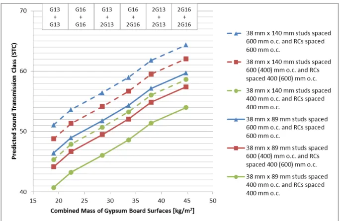
Some constraints should be noted. All cases used for the analysis had sound-absorbing material essentially filling the cavities, which removed absorption thickness from the significant variables, and restricts application of the equation to similar constructions. To estimate the STC rating for a specific construction, insert parameter values from Table 2.2.2 in Equation 2.2.1, or use the calculated STC results for common cases shown in Figure 2.2.3.
Table 2.2.2: Typical values for the parameters in Equation 2.2.1. These essentially span the ranges for the data set and hence define limits for applying the equation.
m1 or m2:
9.5 (kg/m2) for each layer of 12.7 mm fire-rated gypsum board 11.2 (kg/m2) for each layer of 15.9 mm fire-rated gypsum board CavityDepth: 102 (mm) for 38 mm x 89 mm (2x4) studs
153 (mm) for 38 mm x 140 mm (2x6) studs
AbsDens:
13 (kg/m3 )for glass fibre batts 34 (kg/m3 )for mineral fibre batts 50 (kg/m3 )for blown-in cellulose
Ncontacts:
6.25 for Stud_Spacing = 400 mm o.c. and RC_Spacing = 400 mm o.c. 4.17 for Stud_Spacing = 400 mm o.c. and RC_Spacing = 600 mm o.c. 4.17 for Stud_Spacing = 600 mm o.c. and RC_Spacing = 400 mm o.c. 2.78 for Stud_Spacing = 600 mm o.c. and RC_Spacing = 600 mm o.c.
Figure 2.2.3: STC values calculated using Equation 2.2.1 for glass fibre batts (AbsDens = 13) filling the
Chapter 2: Sound Transmission through Wood-Framed Walls and Floors
2.3 Wall Assemblies Framed with 2 Rows of Wood Studs
The focus of this section is the direct sound transmission loss of wall assemblies framed with two rows of wood studs on separate plates with gypsum board attached on both sides of the studs. The gypsum board was fastened directly to the studs. Most of the tested assemblies had sound-absorbing material in the cavities between the studs in one row or both rows.
The typical construction of the wall assemblies described in this Section had a double row of wood studs on separate plates as shown in Figure 2.3.1.
Figure 2.3.1:
Horizontal cross-section of a wall assembly with a double row of wood studs showing the typical components. Variations and element properties are listed in more detail on the right.
1. Double row of wood studs1 (with cross-section 38 mm x 89 mm) nominally spaced either 400 mm (16 in.) or 600 mm (24 in.) on centre, each on a separate 38 mm x 89 mm plate, with a space of 25 mm (1/2 in.) between the two rows of studs. 2. Surface of 1 or 2 layers of fire-rated gypsum board2
screwed directly to one face of the wood studs. Gypsum board may be designated either as G13 (nominal thickness of 1/2 in., 12.7 mm) or as G16 (nominal thickness of 5/8 in., 15.9 mm).
3. Sound-absorbing material3 in the cavities between studs may be glass fibre batts (GFB) or mineral fibre batts (MFB) or blown-in cellulose fibre (CFL)
approximately filling the cavities. There may be sound-absorbing material on one side or both sides. 4. Surface of 1 or 2 layers of fire-rated gypsum board2
screwed directly to one face of the wood studs. Gypsum board may be designated either as G13 (nominal thickness of 1/2 in., 12.7 mm) or as G16 (nominal thickness of 5/8 in., 15.9 mm).
Drawings are not exactly to scale.
NOTE: For the notes on this page please see the corresponding endnotes on page 166.
NOTE: The tests reported in this section include results from different test series. The year of testing is
coded in the report number for each result. The older tests (1992 to 2005) are documented in the referenced reports and are the basis for the tables of STC ratings in Part 9 of the National Building Code of Canada. Repeated tests indicate that the older results are consistent with newer ones within the expected range of reproducibility for the test method.
Chapter 2: Sound Transmission through Wood-Framed Walls and Floors
Table 2.3.1: Measured STC values for wall assemblies with a double row of wood studs1 on separate plates with a space of 25 mm between the rows with stud cross-section of 38 mm x 89 mm (coded as DWS89). The results are numbered and organized in groups by common features within each group. All listed assemblies have sound-absorbing material in the cavities between the studs (on one side or both sides), and all have fire-rated gypsum board.
Specimen
ID Descriptive Short Code
Reference STC NBCC NRC Test DWS89-13a G16_DWS89(400,600)_2MFB89_G16 W13a TL93-263,264,266,281,292 57 DWS89-14a G16_DWS89(400,600)_2MFB89_2G16 W14a TL93-267,282 61 DWS89-15a 2G16_DWS89(400,600)_2MFB89_2G16 W15a TL93-269,283 66 DWS89-13b G13_DWS89(400,600)_2MFB89_G13 W13b TL93-270, 278 57 DWS89-14b G13_DWS89(400,600)_2MFB89_2G13 W14b TL93-271,285 61 DWS89-15b 2G13_DWS89(400,600)_2MFB89_2G13 W15b TL93-272,286 65 DWS89-13c G16_DWS89(400,600)_MFB89_G16 W13c TL93-265,295 54 DWS89-14c G16_DWS89(400,600)_MFB89_2G16 W14c TL93-312 57 DWS89-15d 2G16_DWS89(400,600)_MFB89_2G16 W15d TL93-313 62 DWS89-13d G13_DWS89(400,600)_MFB89_G13 W13d TL93-279,296 53 DWS89-14d G13_DWS89(400,600)_MFB89_2G13 W14d 57 DWS89-15e 2G13_DWS89(400,600)_MFB89_2G13 W15e 60 NOTES:
1. The listed STC values correspond to the values in Table 9.10.3.1. of the 2015 National Building Code of Canada (NBCC).
2. Entries in the table show MFB fo i e al o o k fibre batt), but GFB (glass fibre batt) or CFL (blown-in cellulose fibre) of similar thickness would usually have the same STC rating.
3. Note that entries for walls in the W13x, W14x and W15x series in the NBCC are nominally for spacing of either 400 mm or 600 mm between the stud centres. The regression analysis presented below suggests that the STC rating would be higher by 1 on average with the larger spacing. 4. Results from individual NRC tests scatter around STC values in NBCC Table 9.10.3.1., typically
within a range smaller than ±2 as noted below in the discussion of trends. Some NRC Test References are blank because there is no test corresponding to those specimen details.
Chapter 2: Sound Transmission through Wood-Framed Walls and Floors
Trends in the Sound Transmission for Wood-Framed Walls with 2 Rows of Studs
The effects of key parameters on the sound transmission loss of wood-framed walls with a double row of studs on separate plates were evaluated by regression analysis. This regression equation was developed as one of the algorithms for a software tool called SOCRATES (for SOund Classification RATing
EStimator) [16.9]. Most of the 48 double-stud walls used for the analysis used 38 mm x 89 mm wood
studs. Thirteen of the walls were constructed using steel studs. There was no significant dependency on stud type. The factors varied included:
Type, thickness, and number of layers of gypsum board Type and thickness of the sound-absorbing material Dimensions and spacing of the studs
Cavity depth
The regression analysis yields Equation 2.3.1 for estimating STC ratings:
= . + . [log
+ log
] + .
[
�
ℎ] + .
[�
ℎ� ]
+ .
[
]
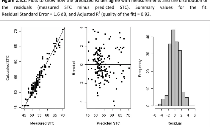
Eq. 2.3.1The quality of the fit is indicated in Figure 2.3.2. The significant parameters are:
and are the masses per unit area (kg/m2) of the gypsum boards on each face of the wall � ℎis the distance between the internal faces of gypsum board in mm
� ℎ� is the thickness of the sound-absorbing material in mm is the distance between stud centres in mm
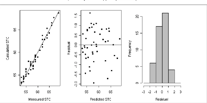
Figure 2.3.2: Plots to show how the predicted values agree with measurements and the distribution of
the residuals (measured STC minus predicted STC). Summary values for the fit: Residual Standard Error = 0.85 dB, and Adjusted R2 (quality of the fit) = 0.96.
Chapter 2: Sound Transmission through Wood-Framed Walls and Floors
To estimate the STC rating for a specific construction, insert parameter values from Table 2.3.2 in Equation 2.3.1, or use the calculated STC results for common cases shown in Figure 2.3.3.
Table 2.3.2:
Typical values for the parameters in Equation 2.3.1. These essentially span the ranges for the data set and hence define limits for
applying the equation.
m1 or m2:
1 or 2 layers on each side of:
9.5 (kg/m2) for each layer of 12.7 mm fire-rated gypsum board 11.2 (kg/m2) for each layer of 15.9 mm fire-rated gypsum board CavityDepth: 203 (mm) for 38 mm x 89 mm (2x4) studs with 25 mm space
AbsThick: 89 mm for batts filling spaces between one row of studs 178 mm for batts filling spaces between both rows of studs StudSpace: 400 or 600 (mm) between the stud centres
Figure 2.3.3: STC values calculated using Equation 2.3.1 for a wall framed with two rows of
38 mm x 89 mm studs with each row on a separate plate (CavityDepth = 203 mm), with sound-absorbing material filling the inter-stud cavities of one row or both rows of studs and the other parameters as identified by the labels on the graph.
Chapter 2: Sound Transmission through Wood-Framed Walls and Floors
2.4 Wall Assemblies for Wood-Framed Mid-Rise Buildings
This section focusses on a series of wood stud walls particularly evaluated for use in mid-rise buildings, though the walls discussed here can be used in any context where their structural capabilities are useful to meet structural design requirements. The test series included numerous constructions, most with two staggered rows of wood studs on a common plate and many including a wood shear membrane.
The data from the study of mid-rise constructions was originally presented in Report A1-100035-02.1 [16.14], which should be consulted for additional construction details about fasteners and material properties. This Report presents only a subset of the data from Report A1-100035-02.1, including results for sound transmission through wood-framed wall assemblies in this Section, and tables of measured Flanking STC values for these walls combined with wood-framed floors in Sections 3.7 and 3.8.
For the wall designs with two rows of studs, an extended version of the coding was used where the first part (such as SWS140) gives a code indicating the stud layout and the total thickness of the wall framing, and the following code in parentheses indicates the size and spacing for the studs in each row. All of the assemblies had bottom plates and top plates matching the total depth of the wall framing. There are several variants on the coding, reflecting the different framing variants tested in the study.
Table 2.4.1 presents data for wall assemblies with two staggered rows of 38 mm x 89 mm (2x4) wood
studsattached to common 38 mm x 140 mm (2x6) bottom plates and top plates. Note that wall MR-SWS-06 in Table 2.4.1 is an average of 3 cases that have PLY16 shear membrane. These results show that the orientation of the shear membrane (long axis of the sheets horizontal or vertical) had negligible effect on the STC rating, and that blocking with 38 mm x 140 mm (2x6) framing supporting the joint between the sheets of the shear membrane provides only a minimal benefit (STC +1).
Table 2.4.2 illustrates the reduction of STC values due to adding additional framing at the wall ends or
by adding studs, versus the improvement for mounting gypsum board on resilient channels. It is interesting that wall 14 in Table 2.4.2 had an STC rating of just 50 (versus STC 49 for MR-SWS-08), despite the huge increase in weight due to added wood. For wall MR-SWS-14, the resilient channels provide a large benefit – without the resilient channels, the STC would drop to 36.
Table 2.4.3 presents the acoustical performance of walls framed with staggered 38 mm x 140 mm (2x6)
studs with 38 mm x 184 mm (2x8) top plates and bottom plates, with variations demonstrating the effect of a shear layer, or adding extra framing members at the ends of the wall assembly, or supporting the gypsum board on resilient channels.
Table 2.4.4 shows the change due to replacing the 38 mm x 140 mm (2x6) studs of the assemblies in
Table 2.4.3 with tripled 38 mm x 140 mm (2x6) studs at the same spacing. For the assemblies without resilient channels, adding the extra studs significantly lowers the STC value relative to the corresponding assemblies in Table 2.4.3. For assemblies that have resilient channels, the change is small.
Chapter 2: Sound Transmission through Wood-Framed Walls and Floors
Table 2.4.5 presents the acoustical performance of walls framed with a single row of 38 mm x 140 mm
(2x6) studs with matching 140 mm bottom plates and top plates, with variations demonstrating the effect of a wood shear panel layer, or adding extra studs to the wall assembly.
For the assemblies in Table 2.4.5, the smaller cavity depth and reduced weight of the framing (with just a single row of studs) lower the STC values by 5 or more relative to constructions with matching surface details in the preceding tables. Because of the very small 200 mm spacing between the studs, the regression expression in Section 2.2 does not properly apply, but the STC values for MR-SWS-28 and -29 seem to be about 2 points lower than that regression expression would predict.
Table 2.4.6 presents the performance of walls framed with a dou le o of flat ise ood studs
(turned with their short dimension perpendicular to the wall surface) sandwiching a shear membrane on 38 mm x 89 mm (2x4) bottom plates and top plates, creating a shear-braced framing assembly just 89 mm deep.
In addition to the two rows of 38 mm x 140 mm (2x6) framing evident in the schematics in Table 2.4.6, these assemblies also had 38 mm x 140 mm (2x6) elements sandwiching the shear membrane where the plywood panels join, and had 38 mm x 89 mm (2x4) u kli g studs fastened to both exposed 38 mm-wide faces of the 38 mm x 89 mm (2x4) flat ise e d studs.
The walls in Table 2.4.6 have the designation SHWS89 (for SHear Wood Stud wall with thickness 89 mm) follo ed a ode i pa e theses su h as W“ @ to ide tif details t pe of f a i g e e s and spacing in mm between their centres fo the t o o s of flat ise studs.
Chapter 2: Sound Transmission through Wood-Framed Walls and Floors
Table 2.4.1: Measured STC values for wall assemblies intended for mid-rise buildings, with two
staggered rows of 38 mm x 89 mm (2x4) wood studs1 attached to common 38 mm x 140 mm (2x6) bottom plates and top plates. Some of these assemblies include a shear membrane of plywood or OSB. These assemblies all have 90 mm sound-absorbing batts in the cavities between the studs on one side, and have fire-rated gypsum board fastened directly to the framing.
Specimen ID Descriptive Short Code
Reference STC Mid-Rise NRC Test MR-SWS-01 2G13_SWS140(WS89@400)_GFB90_2G13 1W, 15W TLA-11-043, 044, 046, 048, 049, 050, 052 50 MR-SWS-02 G16_SWS140(WS89@400)_GFB90_G16 2W, 16W TLA-11-043, TLA12-004 44 MR-SWS-03 2G13_OSB10_SWS140(WS89@400)_GFB90_2G13 3W TLA-11-060 51 MR-SWS-04 2G13_PLY10_SWS140(WS89@400)_GFB90_2G13 4W TLA-11-061 52 MR-SWS-05 2G13_OSB16_SWS140(WS89@400)_GFB90_2G13 5W TLA-11-062 52 MR-SWS-06 2G13_PLY16_SWS140(WS89@400)_GFB90_2G13 6W, 7W, 8W TLA-11-063, 064, 071 51
Note: Assembly numbering generally follows that in Report A1-100035-02.1 [16.14], which should be
Chapter 2: Sound Transmission through Wood-Framed Walls and Floors
Table 2.4.2: Measured STC values for wall assemblies intended for mid-rise buildings, with two
staggered rows of 38 mm x 89 mm (2x4) wood studs1 attached to common 38 mm x 140 mm (2x6) bottom plates and top plates. Some of these assemblies include additional framing members and some have resilient metal channels supporting the gypsum board on one face of the wall. All of these walls have 90 mm sound-absorbing batts in the cavities between the studs on one side, and all have fire-rated gypsum board.
Specimen ID Descriptive Short Code
Reference STC Mid-Rise NRC Test MR-SWS-07 2G13_RC13(600)_SWS140(WS89@400)_GFB90_2G13 3WS TLA-11-059 59 MR-SWS-08 2G13_SWS140(WS89@400)_GFB90_2G13, [WS140 at ends] 1WSa TLA-11-043, 044 49 MR-SWS-09 2G13_SWS140(WS89@400)_GFB90_2G13, [6WS140 at ends] 9W TLA-11-076 47 MR-SWS-10 2G13_RC13(600)_SWS140(WS89@400)_GFB90_2G13, [6WS140 at ends] 10W TLA-11-078 54 MR-SWS-11 2G13_SWS140(3WS89@400)_GFB90_2G13 11W TLA-11-083 49 MR-SWS-12 2G13_RC13(600)_SWS140(3WS89@400)_GFB90_2G13 12W, 12Wa, 12Wb TLA-11-084, 085, 086 55 MR-SWS-14 2G13_RC13(600)_SWS140(WS89@100)_GFB90_2G13 14W TLA-11-091 50
Note: Assembly numbering generally follows that in Report A1-100035-02.1 [16.14], which should be
Chapter 2: Sound Transmission through Wood-Framed Walls and Floors
Table 2.4.3: Measured STC values for wall assemblies intended for mid-rise buildings, with two
staggered rows of 38 mm x 140 mm (2x6) wood studs1 attached to common 38 mm x 184 mm (2x8) bottom plates and top plates. Some of these assemblies include additional framing members and some have resilient metal channels supporting the gypsum board on one face of the wall. All of these walls have 152 mm sound-absorbing batts in the cavities between the studs on one side, and all have fire-rated gypsum board.
Specimen ID Descriptive Short Code
Reference STC Mid-Rise NRC Test MR-SWS-18 2G13_SWS184(WS140@400)_GFB152_2G13 18W TLA-12-059, 060 50 MR-SWS-19 2G13_RC13(600)_SWS184(WS140@400)_GFB152_2G13 19W TLA-12-061 59 MR-SWS-20 2G13_SWS184(WS140@400)_GFB152_2G13, [6WS184 at ends] 20W TLA-12-062 48 MR-SWS-21 2G13_RC13(600)_SWS184(WS140@400)_GFB152_2G13, [6WS184 at ends] 21W TLA-12-063 56 MR-SWS-22 2G13_PLY16_SWS184(WS140@400)_GFB152_2G13 22W TLA-12-081 51 MR-SWS-23 2G13_PLY16_SWS184(WS140@400)_GFB152_RC13_2G13 23W TLA-12-082 61
Note: Assembly numbering generally follows that in Report A1-100035-02.1 [16.14], which should be
Chapter 2: Sound Transmission through Wood-Framed Walls and Floors
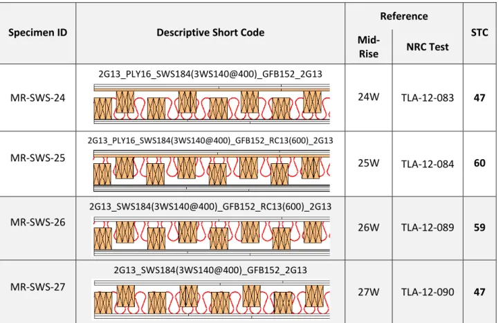
Table 2.4.4: Measured STC values for wall assemblies intended for mid-rise buildings, with two
staggered rows of tripled 38 mm x 140 mm (2x6) wood studs1 attached to common 38 mm x 184 mm (2x8) bottom plates and top plates. Some of these assemblies include shear membranes and some have resilient metal channels supporting the gypsum board on one face of the wall. All of these walls have 152 mm sound-absorbing batts in the (rather small) cavities between the studs on one side, and all have fire-rated gypsum board.
Specimen ID Descriptive Short Code
Reference STC Mid-Rise NRC Test MR-SWS-24 2G13_PLY16_SWS184(3WS140@400)_GFB152_2G13 24W TLA-12-083 47 MR-SWS-25 2G13_PLY16_SWS184(3WS140@400)_GFB152_RC13(600)_2G13 25W TLA-12-084 60 MR-SWS-26 2G13_SWS184(3WS140@400)_GFB152_RC13(600)_2G13 26W TLA-12-089 59 MR-SWS-27 2G13_SWS184(3WS140@400)_GFB152_2G13 27W TLA-12-090 47
Note: Assembly numbering generally follows that in Report A1-100035-02.1 [16.14], which should be
Chapter 2: Sound Transmission through Wood-Framed Walls and Floors
Table 2.4.5: Measured STC values for wall assemblies intended for mid-rise buildings, with one row of
38 mm x 140 mm (2x6) wood studs1 attached to 38 mm x 140 mm (2x6) bottom plates and top plates. Some of these assemblies include shear membranes. All of these walls have 152 mm sound-absorbing batts in the cavities between the studs, and all have fire-rated gypsum board, with resilient metal channels supporting the gypsum board on one face of the wall.
Specimen ID Descriptive Short Code
Reference STC Mid-Rise NRC Test MR-SWS-28 2G13_WS140@200_GFB152_RC13(600)_2G13 28W TLA-12-169 51 MR-SWS-29 2G13_PLY16_WS140@200_GFB152_RC13(600)_2G13 29W TLA-12-161 51 MR-SWS-30 2G13_PLY16_3WS140@200_GFB152_RC13(600)_2G13 30W TLA-12-167 53 MR-SWS-31 2G13_3WS140@200_GFB152_RC13(600)_2G13 31W TLA-12-168 53
Note: Assembly numbering generally follows that in Report A1-100035-02.1 [16.14], which should be
Chapter 2: Sound Transmission through Wood-Framed Walls and Floors
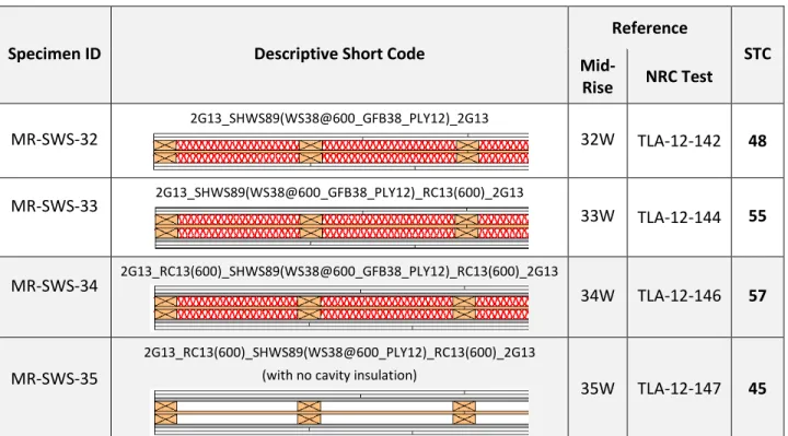
Table 2.4.6: Measured STC values for wall assemblies intended for mid-rise buildings, with 89 mm thick
framing comprising two rows of flatwise 38 mm x 89 mm (2x4) wood studs1 sandwiching a shear membrane and framed at all 4 edges by 38 mm x 89 mm (2x4) wood members (bottom plate, double top plates, a d u kli g studs . All assemblies have a 12 mm plywood shear membrane sandwiched between the two rows of studs and all have fire-rated gypsum board on both faces. Some assemblies have resilient metal channels supporting the gypsum board on one or both faces of the wall, and most have 38 mm sound-absorbing batts in the cavities between both rows of studs.
Specimen ID Descriptive Short Code
Reference STC Mid-Rise NRC Test MR-SWS-32 2G13_SHWS89(WS38@600_GFB38_PLY12)_2G13 32W TLA-12-142 48 MR-SWS-33 2G13_SHWS89(WS38@600_GFB38_PLY12)_RC13(600)_2G13 33W TLA-12-144 55 MR-SWS-34 2G13_RC13(600)_SHWS89(WS38@600_GFB38_PLY12)_RC13(600)_2G13 34W TLA-12-146 57 MR-SWS-35 2G13_RC13(600)_SHWS89(WS38@600_PLY12)_RC13(600)_2G13 (with no cavity insulation)
35W TLA-12-147 45
Note: Assembly numbering generally follows that in Report A1-100035-02.1 [16.14], which should be