Management of Complexity
Research Project
Hans-Georg B¨
using
Prof. R. John Hansman
Contents I
List of Acronyms III
Executive Summary 1
1 Introduction 2
2 Structure and Cognitive Complexity 4
2.1 Complexity Types . . . 4
2.2 A Generalized ATC Process Model . . . 5
2.3 Structure in the ATC Environment . . . 7
2.3.1 Standard Flows . . . 8
2.3.2 Groupings . . . 9
2.3.3 Critical Points . . . 10
2.3.4 Responsibility Abstraction . . . 12
2.3.5 Impact of Structure-Based Abstractions . . . 13
2.4 Dynamic Use of Abstractions . . . 14
2.4.1 Operating Modes . . . 16
2.4.2 Complexity and Modal Transitions . . . 18
3 Experimental Study 19 3.1 Design Considerations . . . 19 3.2 Experimental Setup . . . 20 3.2.1 User Interface . . . 20 3.2.2 Experimental Task . . . 20 3.3 Data Collection . . . 23 3.4 Participants . . . 24 3.5 Methodolgy . . . 24 3.5.1 Analysis Approaches . . . 24
4.2 Discussion . . . 34
5 Summary 36
Bibliography 39
ADS-B (Automatic Dependent Surveillance - Broadcast)
ARTCC (Air Route Traffic Control Center)
ATC (Air Traffic Control)
ETMS (Ehanced Traffic Management System)
FAA (Federal Aviation Administration)
FL (Flight Level
IFR (Istrument Flight Rules)
LOA (Letter Of Agreement)
MA (Monitor Alert)
MAP (Monitor Alert Parameter)
MINIT (Minutes In Trail)
MIT (Miles In Trail)
NDB (Nondirectional Beacon)
STAR (Standard Terminal Arrival Route)
SUA (Special Use Airspace)
SWAP (Severe Weather Avoidance Procedures)
TCAS (Traffic Alert and Collision Avoidance System)
TRACON (Terminal Radar Approach Control Facility)
VFR (Visual Flight Rules)
VOR (Very High Frequency Omnidirectional Range)
complexity has been integrated into the Controller Process Model through a Complex-ity Manager. It is hypothesized that the ComplexComplex-ity Manager operates by commanding switches between operating modes.
In order to explore whether these operating modes can be observed in a simple ATC task, an experiment was designed. Participants were given scenarios with varying traffic levels. Their commands and their performance have been collected and analyzed. The experimental results show participants appeared to use each of the hypothesized operating modes. The use of the structure in each mode was also as expected.
Introduction
The Air Traffic Control (ATC) system plays a critical role in enabling the rapid move-ment of people and goods through national and international economies. However, the ability of ATC to continue to provide efficient services is being challenged by the continued rapid growth of air traffic.
The perceived seriousness of the consequences of an error in the ATC system is an important factor influencing the operation of the system. For example, a recent near-miss at Logan International Airport in Boston raised questions regarding the use of intersecting runways controlled by two controllers operating on different frequencies (NTSB 2005).
The potential for controllers in the system to be overloaded due to excessive com-plexity is considered to be a critical risk. This risk is managed, in part by restricting the capacity of the system so that controllers are not overloaded. In the United States, limits on sector capacity are based on the number of aircraft in the sector. The Monitor Alert (MA) is a function of the Enhanced Traffic Management System (ETMS) that places an alert when the sector capacity is expected to be exceeded (FAA 1997). The Monitor Alert Parameter is based on the average sector flight time and the number of aircraft in the sector.
The limitations of using the number of aircraft have been recognized and there have been several efforts aimed at increasing the sophistication of this measure. A technical workshop related to a new aviation concept called “free flight” initiated research interest in the concept of ATC complexity (Planzer/Hofmann 1995). The concept of dynamic density was introduced as a means of estimating when an air traffic situation was so complex that a central control authority was needed. Various researchers have identi-fied lists of key complexity factors that appear to drive complexity and hence should be captured in any complexity metrics (Sridhar et al. 1998). (Laudeman et al. 1998) and (Wyndemere 1996) are two examples of metrics that attempt to capture a more sophisticated understanding of complexity.
None of the proposed approaches have been widely accepted as complete and de-finitive. A core concern has been the failure to capture the role that structure in the
what the overall situation is.
This research project has extended the previous efforts to understand how structure-based abstractions are used by air traffic controllers to manage the complexity of con-trolling a situation. Changes in controller behavior and the use of structure-based abstractions are thought to be observable through measures of overall system efficien-cy. In order to explore whether complexity management strategies could be observed in an ATC like setting, an experiment probing changes in behavior and use of built-in structure in a simplified ATC task was designed and executed. The results have pro-vided empirical evidence of the importance of understanding of how the management of complexity is reflected in changes in controller behavior.
An improved understanding of how structure impacts cognitive complexity can be used to provide guidance for airspace and procedure design. The development of more precise and operationally meaningful complexity limits will also be improved if the effects of structure can be captured and understood. Finally, the introduction of new technologies may fundamentally change the underlying structure in the ATC system. For example, ADS-B technology may allow the introduction of new procedures such as limited self-separation. This may change the underlying flow patterns within the ATC system, potentially disrupting the controller’s structure-based abstractions, increasing the complexity. By understanding how structure is currently used, some of the negative potential consequences of these new technologies can be anticipated and mitigation strategies developed.
Chapter 2 of this report reviews the previous work on complexity and identifies complexity management as an important research area. Chapter 3 describes the ex-periment and discusses approaches to analyzing the data. In the fourth chapter the experimental results and their interpretation are presented. Finally, conclusions drawn from the experiment are discussed and future research directions identified.
Structure and Cognitive
Complexity
In order to understand how structure influences complexity, the International Center for Air Transportation at the Massachusetts Institute of Technology has conducted a series of experiments and observations. This chapter reviews this previous work and the observations that identified the potential importance of the role of structure in complexity management.
2.1
Complexity Types
Complexity appears to be an intuitive if difficult to define concept. Based on field observations, focused interviews and analysis of ATC system operations several distinct types of complexity within the ATC operational context have been identified.
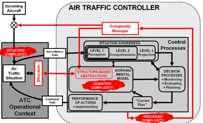
These types of complexity are Situation Complexity, Cognitive Complexity, and Perceived Complexity and the relationships between them are illustrated in Figure 2.1. As shown in the figure, Situation Complexity is a product of the ATC operational context. It is a property associated with directly measurable quantities in the world; for example, the number of aircraft in a sector is a metric of Situation Complexity.
However, Situation Complexity is not necessarily the complexity of controlling the situation as experienced by the controller. As shown in the figure, Cognitive Complexity is the complexity associated with the actual cognitive processes used by the controller to complete the control loop.
There are many ways one could complete the control loop. Each one would cause a different Cognitive Complexity. A controller could either consider the dynamics of aircraft at a highly detailed level (e.g. considering engine performance at different flight levels) leading to a high level of Cognitive Complexity, or he could rely on dynamics at a low detailed level (e.g. standard turns). A simple model is neither sufficient nor necessary to simplify a task.
Figure 2.1: Simplified ATC Process Model
2.2
A Generalized ATC Process Model
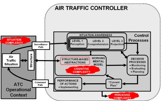
The model in Figure 2.1 provides a basis for understanding the factors that influence each of the types of complexity. In order to understand how structure may influence and impact Cognitive Complexity a generalized model of the control processes used by an air traffic controller has been generated and is presented in Figure 2.2. In the model a surveillance path feeds the controller with information about the situation be-ing controlled. The processbe-ing of the information is represented in terms of an adapted version of Endsley’s model of situation awareness (Endsley 2000). A controllers’ sit-uation awareness represents their understanding of the present state of the system, and its projected states in the near future. Also, a part of the situation awareness is a higher level comprehension in relation to the ATC objectives and a projection of future states.
system embodying knowledge and experience of the ATC controller. The working men-tal model is considered a quasi-static attribute of the controller’s cognitive processes although it is evolving and growing with experience. The working mental model is formed in part by abstractions, or simplified versions of an actual system’s dynamics.
Figure 2.2: Generalized ATC Process Model
In order to be able to manage information within the constraints of human memory and processing limitations, abstractions are used to represent the essential character-istics of a mental model in a more cognitively compact form. Rasmussen states that the abstraction process is “not merely removal of details of information on physical or material properties. More fundamentally, information is added on higher level princi-ples governing the co-function of the various functions or elements at the lower levels” (Rasmussen 1986). After using an abstraction to simplify part of the mental model, the human is able to attend to a simplified version of the entire system in his or her working mental model.
Abstractions are a powerful tool as they allow the controller to perform a task at the same level of performance as if a detailed model of the system properties had been used. If an abstraction allows a controller to accurately perform the required task, they do not need to attend to a detailed and comprehensive mental model. This is hypothesized to reduce the Cognitive Complexity of performing that task, allowing the controller to attend to other aspects of the system (see Figure 2.3).
Figure 2.3: Illustration of the abstraction benefits (Reynolds et al. 2002)
situation awareness support the key decision making processes of monitoring, evaluat-ing and plannevaluat-ing (Pawlak et al. 1996). Monitorevaluat-ing involves the checkevaluat-ing of the confor-mance of the current air traffic situation against those expected, based on the current plan. Evaluating verifies the effectiveness of the plan in meeting all of the current and projected constraints and goals associated with the sector. If the evaluation process detects the need for an intervention by the controller, the planning process can be triggered. The planning processes lead to a current plan that is a distinct cognitive element. It is an internal representation of the schedule of events and commands to be implemented. Furthermore, it includes the resulting aircraft trajectories, ensuring that the given commands will lead to a safe and efficient routing. Based on the current plan, the controller implements commands that modify how the air traffic situation evolves completing the command loop.
2.3
Structure in the ATC Environment
Structure in the air traffic situation will influence how that situation will evolve. A controller can use knowledge of the effect of this structure as the basis for abstractions that can be used in the working mental model. By shaping the expected and typical trajectories of aircraft in a particular sector, the underlying structure in the airspace constrains and influences the future states of the air traffic situation. Structure-based abstractions simplify the task by reducing the number of possible future states that must be evaluated by the controller and by simplifying the working mental model used in the control process.
An investigation by Histon et al. (Histon et al. 2002) has identified four key ab-stractions based on structure that seem to reduce cognitive complexity in ATC. These are:
• Standard Flows • Groupings • Critical Points
• Responsibility
In the following subsections each of them is described briefly.
2.3.1 Standard Flows
An important structure-based abstraction is standard flows. They are mainly estab-lished by:
• Explicit structural elements • Standardized Operations
Figure 2.4: Example of arrival flows into O’Hare airport in Chicago (Histon et al. 2002)
The first type of standard flow is based on explicit structural elements in the airspace. They are represented by navigational aids (such as VORs, NDBs or VOR-TACs) or by documented standardized procedures, including standard ingress and egress points, defined by Letters of Agreement (LOA) between two adjacent facili-ties. An example for this type of flow is an arrival stream into Chicago O’Hare airport shown in Figure 2.4.
Secondly, a type of standard flow emerges as a result of common practices. These are standardized but unpublished patterns of operation. An example is the typical “trombone” vectoring used to merge aircraft onto final approach.
Being a member of a standard flow associates a set of higher-level attributes to an aircraft. These are ingress and egress points, an expected future routing, and locations of probable encounters. They form a generalized expectation of an aircraft’s trajectory through the airspace.
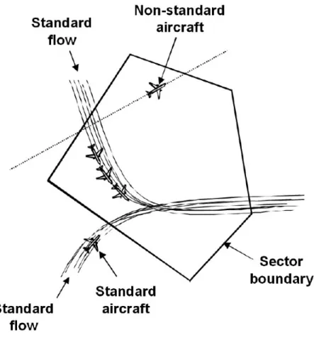
The standard flow abstraction is a means of classifying aircraft into non-standard and standard classes depending on whether they are members of an established flow pattern or not (see Figure 2.5). The task of projecting the future behavior of a standard flow aircraft is significantly simplified by the generalized expectation of its trajectory.
Figure 2.5: Illustration of the standard flow abstraction
Standard flows also provide a simplified basis for the monitoring task. Aircraft not operating in the standard pattern do not benefit from the standard flow abstraction.
The simplification of the projection and monitoring task makes the standard flow abstraction powerful. Even when there are a large number of aircraft in the sector it remains available to the controller if the aircraft are conforming to the standard flow basis.
2.3.2 Groupings
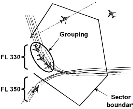
Common properties are the basis for creating groups of aircraft. This type of abstraction can take advantage of properties that are known to segregate a traffic situation into non-or minimally interacting groups. Consequently, the aircraft groups can be projected independently, reducing the Cognitive Complexity.
A simple example of that abstraction is the standard flight level that associates directions of travel with particular altitudes. This allows controllers to project and manage each flight level independently, since this abstraction eliminates some aircraft-aircraft interactions from consideration for aircraft-aircraft that are in level flight. Aircraft that are ascending or descending between different flight levels must be treated as special
Figure 2.6: Illustration of the grouping abstraction
cases as they do not fit into this abstraction.
Furthermore, a grouping abstraction can be based on the type and specifications of the aircraft. The more uniform the aircraft performance is within a sector, the more likely it is that a grouping abstraction will be available. For example, a wide distribution of speeds makes it more difficult to project the future positions compared to the case where all aircraft are flying at a uniform speed.
Finally, proximity can be used as the basis of a grouping abstraction. In this case, the use of a grouping abstraction can act to simplify the output from a controller, i.e. the issued commands resulting from the decision process. An identical clearance command can be given to each group.
2.3.3 Critical Points
A third example of a structure-based abstraction is the critical point abstraction. The abstraction is based on known “hot-spots”, or locations where controllers know to expect potential conflicts. The underlying airspace structure, in the form of crossing and merge points of flows, will tend to concentrate aircraft-aircraft encounters at common locations. These locations can be used as the basis for a critical point abstraction.
Critical point abstractions can be used to reduce the cognitive complexity of moni-toring, evaluating, and planning solutions to potential problems around these locations by reducing the search space over which aircraft trajectories are evaluated. By allowing a controller to focus on a finite number of critical locations, the critical point
abstrac-Figure 2.7: Illustration of the critical point abstraction
tion reduces the Cognitive Complexity of managing the air traffic situation. Focusing on the intersection points of aircraft flows simplifies the controller’s task since he does not have to do a pair-wise analysis for every aircraft (Pawlak et al. 1996).
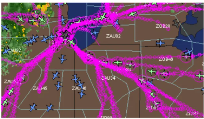
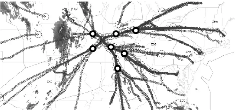
Figure 2.8: White dots are examples of critical points in the standard arrival flows into O’Hare airport in Chicago (21:00 EDT, May 3, 2001)
The power of a critical point abstraction emanates from the reduction of a multi-dimensional interaction problem to a one multi-dimensional time-of-arrival at the merge point problem. The critical point abstraction allows a controller to solve only a phasing prob-lem. The controller only need to monitor that the aircraft avoid the aircraft ahead and behind in the flow. Without a critical point abstraction, the same encounter geometry
may require consideration of multiple dimensions, making the projection task more difficult.
Several examples of localized critical points in the form of merge points in an arrival stream can be seen in Figure 2.8, which shows the arrival flows into O’Hare airport in Chicago. Merges occur at well defined spatial locations, allowing controllers to simplify their projection of the interaction between two aircraft in different arrival streams to a one dimensional issue of time-of-arrival at the critical point.
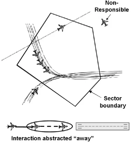
2.3.4 Responsibility Abstraction
The responsibility abstraction is based on the transfer of responsibility for a portion of the separation task to another part of the ATC system. A common way is transferring tasks to pilots or other controllers. A typical trade of a responsibility would be hand-ing off aircraft to the downstream controller while the aircraft are still in the sector. Common transfers of responsibility to pilots are visual approach clearances such as “maintain visual separation” under good VFR conditions.
Figure 2.9: Illustration of the responsibility point abstraction
situation is structured.
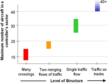
Figure 2.10: Illustration of the impact of structure-based abstracions
The controllers were asked to estimate how many aircraft they are able to handle under certain applications of structure. In this case, different structures in the airspace result in different assemblage of the ATC tasks. If the traffic is concentrated onto the tracks, the controller primarily has to accomplish monitoring task. A situation with many crossings forces the controller to solve the evaluating and planning tasks.
2.4
Dynamic Use of Abstractions
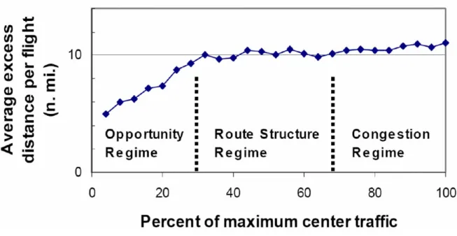
Having identified structure-based abstractions, an immediate question is when and how often they are used. Some evidence suggesting their use may be quite dynamic has been found in data analyzed by Howell et al. Howell analyzed the relationship between traffic levels and routing inefficiency in the enroute environment. Inefficiency in this study was considered to be the excess distance over a great circle path between each aircraft’s entry and exit points from an Air Route Traffic Control Center (ARTCC).
Figure 2.11: Average excess distance per flight in enroute centers versus center traffic load (Howell et al. 2003)
The data analyzed by Howell is presented in Figure 2.11. The curve shows three linear parts that seem to have distinct kinks. At low load levels the excess distance is low, growing linearly with the load level until a plateau is reached at about 30% of the maximum center traffic. At about 70% the inefficiency rises again.
The figure suggests that the use of structure-based abstractions is dynamic. The changes in excess distance suggest that the controllers do not require aircraft to follow the route structure at low load levels. At moderate load levels, controllers appear to be leaving aircraft on the route structure. This suggests controllers are changing whether the basis for a standard flow abstraction is available or not, and hence whether structure-based abstractions are being used.
The dynamic use of structure suggests that the controller process model in Figure 2.2 is incomplete. Based on the field visits and data from Figure 2.11, it is clear that controllers have the opportunity to actively manage and regulate complexity. Complex-ity management can occur through changing the operating conditions (e.g. by
impos-Figure 2.12: Enhanced Generalized ATC Process Model
ing restrictions or by changing use of structure), or through modifying the cognitive processes used (e.g. changing the use of structure-based abstractions).
In order to capture the effect of complexity management in the controller process model, a complexity management loop has been added. Based on the controllers Per-ceived Complexity, a Complexity Manager, hypothesized to be a component part of the central executive (Wickens et al. 1997), will take actions that can modify the Cognitive Complexity. These actions can be through shifts in the cognitive approaches used, for example by modifying whether structure-based abstractions are used, or by prompting changes in the characteristics of the situation under control, for example by regulating the rate of incoming aircraft.
It is expected that as load conditions vary, the complexity manager will act in order to keep the Cognitive Complexity at acceptable levels. It is hypothesized that this can be best understood as the controller switching amongst different modes of operation with each mode producing different levels of Cognitive Complexity.
2.4.1 Operating Modes
An operating mode reflects both internal cognitive approaches of the controller as well as corresponding external behaviors. The changes between different operating modes are hypothesized to lead to changes in system performance. This provides an opportuni-ty for investigating controller complexiopportuni-ty management by observing changes in system performance. For example, operating modes corresponding to variations in the use of structure can be observed by examining metrics of flight path efficiency.
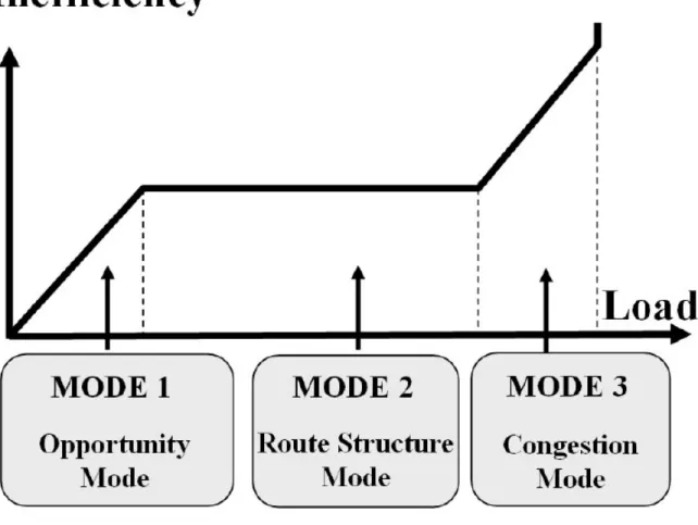
Based on a consideration of previous observations and the data analyzed by Howell (Howell et al. 2003), three possible operating modes that correspond to different uses of structure have been idnetified.
Figure 2.13: Schematic plot of inefficiency versus load in different operating modes
The first mode named Opportunity Mode applies for low traffic levels. It is assumed that a pair-wise control strategy is used and a weak coupling between aircraft exists (see Figure 2.14). Due to the low load level, controllers easily tolerate deviations from the structure. It allows controllers to give efficient routings. This leads to the linear rise of inefficiency vs. load mentioned above.
Figure 2.14: Illustration of the Opportunity Mode
Figure 2.15: Illustration of the Route Struc-ture Mode
Finally, the Congestion Mode reflects that the capacity limit of the structure is being approached. The controller cannot anymore rely on the deconflicting of the structure and management of interactions becomes important. There is a strong inter-structure coupling the controller has to deal with by pulling aircraft off the structure. That is reflected by a rise of inefficiency at high load levels.
2.4.2 Complexity and Modal Transitions
Transitions between the operating modes will be prompted by the complexity manager determining that the current mode is, or will shortly be, no longer supporting accept-able levels of perceived complexity. This process is illustrated in Figure 2.17. As load increases, an operating mode may produce a perceived complexity above a notional “Complexity Tolerance Limit”. In response, the controller is expected to transition to a different operating mode. For example, an unstructured system depicted by the Op-portunity Mode would show a behavior of the Perceived Complexity growing with the square of the load since every aircraft has to be crosschecked with every other aircraft in the sector. A structured system would show a linear behavior since every aircraft only has to be checked with the aircraft next to it. Therefore, the Complexity Tolerance Limit will be reached earlier in the Opportunity Mode than in the Structure Mode. To reduce complexity, a transition to the Structure Mode is required to manage higher load levels.
empirical investigations of the use of structure for complexity management have been found. Furthermore, the data analyzed by Howell was based on aggregate flight effi-ciencies through multiple sectors. In order to provide empirical support for the theory developed in Chapter 2, and to demonstrate that operating modes can be observed in the behavior of a single controller operating in a single sector, an experiment has been designed and performed.
Using a simple ATC-like task, the experiment was designed to address two objec-tives. First, to demonstrate that distinct modes of operation could be observed in participants performing a simple ATC task, and secondly, to explore whether the be-haviors of the participants in those modes are consistent with the expectations of the use of structure and structure-based abstractions.
3.1
Design Considerations
In order to probe the use of modes, and differences in the use of structure within modes, an ATC simulation has been developed. The simulation was designed to capture some of the key elements of air traffic control without being so realistic as to require excessive amounts of training for participants. All aircraft were considered to be at the same altitude, and no altitude changes were provided for. In order to allow participants to have as much freedom as possible in using the built-in structure, both heading and speed commands could be used.
Based on the expected use of structure in the opportunity, route structure, and congested modes of operation, a simple route structure was generated. The tasks and route structure were designed to provide opportunities for participants to engage in pair-wise control strategies by providing aircraft “shortcuts” as well as opportunities for saturation of the capacity of the route structure.
3.2
Experimental Setup
3.2.1 User InterfaceThe simulation system is based on a Matlab ATC simulation designed by Chris Tsonis, MIT. Each aircraft appears as a diamond surrounded by a red circle on the ATC display (see Figure 3.1). The circle represents half the minimum required distance between aircraft. If the circles overlap, the minimum distance has been violated.
Each aircraft also has a data-tag with two lines. The first line is an identifier for the aircraft consisting of an airline and flight number. On the second line of the data-tag is the aircrafts’ current speed in knots.
The right side of the display contains several information screens and command boxes. There is a large red “Stop” button which the participant can press at any time if he/she feels uncomfortable continuing in the experiment. Shortcut requests from aircraft will sometimes appear in the white box just above the “Stop” button.
The participant can change an aircrafts heading or speed. To give vectors to aircraft, a mouse click technique is used. The user can click on either an aircrafts data tag or the diamond indicating its present position. The aircraft will turn white to indicate it is selected, and the cursor will change to a cross hair. Clicking anywhere on the screen will force the aircraft to immediate turn and fly towards that point and will continue on the heading assigned indefinitely. This is indicated by the yellow color.
A very common command in ATC is to give an aircraft a shortcut. This command is realized in the simulation by selecting an aircraft, and clicking within any of the circles depicted on the screen. The aircraft will fly to that circle, and then continue on the standard flight path depicted by the lines on the screen, indicated by the red color of the aircraft.
The speed of the aircraft can be controlled in two ways. When an aircraft is selected the speed can be increased or decreased in 10 knot increments by clicking on the appropriate button in the right hand information bar. To set a specific speed, an aircraft must be selected, the intended speed must be typed inside the white text box, and the “Set” button must be pressed. This button is only available if an aircraft has been selected.
3.2.2 Experimental Task
In this sector, aircraft will enter in two streams on the left edge of the screen. They will converge on a common point and then proceed to the right edge of the screen to an exit marked “C3”. All aircraft must exit in a single file at the middle point of the region labelled “C3”.
Figure 3.2: Possible Abstractions in the experimental ATC Environment
The primary objectives in order of decreasing importance are:
1. Safety: Each aircraft is surrounded by a circle which represents one half the minimum allowable distance between aircraft. If the circles for two aircraft overlap safety has been compromised. A loud beeping noise and flashing red colours will indicate which two aircraft have come too close together.
2. Metering: The participant is asked to provide aircraft 10 miles-in-trail of each other at the hand-off point, and with all aircraft travelling at 300 knots. The waypoints on the screen near the exit are separated by 10 miles. The information bar on the right tells the subject the distance between aircraft as each aircraft leaves the sector.
3. Efficiency: The participant is supposed to give aircraft as many shortcuts as possible, to reduce the distance they have to fly. Aircraft will sometimes ask for a shortcut direct to “C3”.
Figure 3.3: Number of Aircraft on Screen as a Function of Time
Each participant completed one scenario. The number of aircraft present in the sector was varied by changing the input rate. An example of the nominal profile is shown in Figure 3.3.
The peaks and valleys are chosen to vary the load and stimulate use of multiple modes. It ensures that the scenario is not predictable. The peak values are chosen at a level such that metering requirements are impossible to meet without taking aircraft off the structure.
In order to obtain an insight into the participants’ behavior, some performance data is collected. The dependent variables are:
• Excess distance flown per aircraft
• Separation violations of the five mile separation minima
• Performance on metering task (deviations from 300 knots speed requirement and providing less than required minimum spacing (10 MIT))
• Number and type of commands (speed / heading)
3.4
Participants
Fourteen participants completed this experiment. Ten of them are students of the MIT community and four are air traffic control trainees at the end of their training. Several advantages have led to the decision to use both controllers and students as participants for the ATC experiment. Controllers are familiar with the real-life operations. Their results are expected to be similar to the data collected from the current air traffic operations. Moreover, they are likely to be trained to use different strategies under dif-ferent traffic situations. Students are expected to have no training of the use of difdif-ferent strategies for certain air traffic situations. Having them as participants would give fur-ther insight whefur-ther certain approaches to handling traffic situations are independent of a special education.
3.5
Methodolgy
3.5.1 Analysis Approaches
Due to the dynamics of load there are multiple ways of analyzing results. As participants interacted with the traffic in the course of the scenario, not all participants experienced the same traffic load. In order to analyze the data, multiple approaches have been developed. The performance of each aircraft, for example the distance that it flew, can easily be computed. However, there are multiple ways of determining a load to be associated with that performance. The load could be estimated by examining the number of aircraft that were also present. Alternatively, the instantaneous number of aircraft present at a time step can be assumed to be a good estimate of load at that time, and an estimate of performance across the aircraft present can be calculated. The following sections describe these analysis approaches with the example of the total distance flown.
3.5.1.1 Analysis by Aircraft
For this method of analyzing the data, firstly the total distance flown is computed for each aircraft. For example, the total distance flown for each aircraft for a single participant is shown in Figure 3.4.The identity of all aircraft present in the sector at each timestep (N (t) at each timestep) can be computed. This can then be used to identify the profile for N (t) for each individual aircraft. An example profile is shown in Figure 3.5. Based on the profile, an aggregation function (e.g. mean or median) can be used to generate an approximation of the load that the controller was exposed to while the aircraft passed through the sector.
Figure 3.4: Total distance flown for each air-craft vs. airair-craft number
Figure 3.5: Number of aircraft vs. time for an example aircraft
This yields a load for each aircraft distance observation in Figure 3.4. By plotting the observations against theses estimates of load, overall patterns of behavior can be analyzed.
3.5.1.2 Analysis by Timestep
A different approach to the analysis by aircraft is the analysis by time step. The time sequence is divided into discrete steps. For each time step the aircrafts are identified. Since the total distance flown by every aircraft is known, every time step can be assigned an aggregate distance. An example of that aggregation is given in Figure 3.6, which shows an average distance flown of 5.5 grid units computed across four aircraft present at a single timestep for a single participant.
Figure 3.6: Total distance flown for each aircraft vs. aircraft number at a single time step
This provides an estimated performance at each time step which can be plotted against the known number of aircraft present at each time step.
Experimental Results
Analysis of the results from the experiment showed clear evidence of the use of different operating modes. The use of different operating modes could be seen in performance on all parts of the task: efficiency, metering and safety. This chapter presents the core results demonstrating the use of different operating modes; analysis of the use of commands by participants offers further support for the hypothesized differences in the use of structure between Opportunity, Route Structure, and Congestion Modes.
4.1
Analysis of the Existence of Operational Modes
The flight path efficiency of each aircraft has been used as the basis for discriminating between different operating modes. As discussed in Chapter 3, there are multiple ways in which the data collected can be analyzed.
4.1.1 Aircraft Based Identification of Modes
The use of different operating modes appears to have been clearly established by the results of a “By Aircraft” analysis presented in Figure 4.1. At low levels of load, par-ticipants appear to be operating in an opportunity mode, as on average, most aircraft were flying a distance less than the flight path that followed the route structure. At high levels of load, between 12 and 14 aircraft, the average distance flown reaches its peak values, consistent with participants operating in a Congestion Mode.
Two interesting effects are also visible in Figure 4.1. At very high levels of load, the average distance flown appears to decline toward the zero level, corresponding to the flight path distance of the route structure itself. This is thought to be due to partic-ipants operating in a distinct and unanticipated “Giving Up” mode. This effect was supported by qualitative observations that at very high traffic levels participants prior-itized the tasks by how easily they were accomplished as opposed to their importance. Additionally, while it appears a route structure mode can be identified at traffic levels of 7 through 11 aircraft, the average inefficiency is not at the expected level. As
if there were 90 observations of aircraft flying the route structure and 10 aircraft with a distance of 100 nm, the mean that would be calculated is 10 nm.
Figure 4.1: Inefficiency as a function of load suggests participants were using different modes of oper-ation
An additional effect blurring the transition and distinction between Opportunity Mode and Route Structure Mode arose from variations in the performance of different participants. Figure 4.2 shows a magnification of plots of inefficiency versus sector load. The graphs in different colors represent the results for a reduced sample of participants. Figure 4.2, shows that the transition to a Route Structure Mode appears to occur as early as 3 aircraft for some participants, or as late as 7 aircraft for other participants.
Figure 4.2: Data points collected by all participants
behavior. For example, a single aircraft being given a short-cut while nine others are on route structure is not indicative of “Opportunity Mode”.
4.1.2 Categorization Based Indication of Operating Modes
In order to address the sensitivity of the “By Aircraft” approach to the magnitude of the distance flown, an alternative approach based on categorizing the distance has been developed.
Figure 4.4: Categorization of aircraft
As shown in Figure 4.4, three different categories for the distance flown were iden-tified. The mode a participant applies to accomplish the ATC task would then be determined by the relative prevalence of each category. For example, the Opportunity Mode would be allocated, if a more than 50% of the aircraft travel at a distance less than that of the route structure. The Congestion Mode would be observed by see-ing a mix of aircraft in the greater than route structure and equal to route structure
categories.
The percentage of aircraft in each category can be computed for each time step for each participant. These plots can be treated with the time step analysis described above, leading to plots of percentage of aircraft in different modes as functions of the sector load.
Figure 4.5: Percentage of aircraft in different operating modes vs. center traffic load
These plots show a much clearer change in behavior for different traffic loads. At a level of about five aircraft one can observe a trade-off aircraft between Opportunity Mode and Route Structure Mode. Most of the aircraft seem to be left on the route at a load level larger than five aircraft on screen. The percentage of aircraft being given a shortcut quickly drops in this area. This Mode Transition seems to be strong, since the gradients of the relevant curves in this are fairly large.
At traffic levels between 8 and 16 aircraft in the sector, the percentage of aircraft traveling a distance similar to the route structure remains almost constant at a high level of between 50% and 60%. Aircraft in the Opportunity Mode are almost insignifi-cant. However, the fraction of aircraft that have flown a distance larger than on route structure is low but constantly growing. This rise is consistent with participants using a Congestion Mode. Above 12 aircraft more than a quarter of all aircraft flew a distance greater than that of the route structure.
The second significant change in behavior can be observed at a load level of 16 air-craft. The percentage of aircraft traveling at a distance larger than the route structure
modes within each mode, the performance on the metering tasks has also been analyzed. The results strongly support the idea that changes in behavior can be observed at different load levels. Both the analysis of the performance on spacing and speeding requirements at the exit show clear evidence of task shedding.
5
10
15
0
20
40
60
80
100
Mean # of Aircraft Present over full time on screen
Percentage of Aircraft Violating
Minimum Metering Spacing
Figure 4.6: Percentage of aircraft violating the minimum metering spacing vs. traffic load
Figure 4.6 shows the percentage of aircraft violating the minimum metering spacing as a function of the number of aircraft in the sector. A dramatic increase from 10% to 40% occurs between 7 and 9 aircraft on screen. The performance at traffic levels greater than 9 aircraft on screen indicates that the sector load level has reached a state
at which it is impossible for the participant to accomplish all the tasks.
5
10
15
0
20
40
60
80
100
Mean # of Aircraft Present over full time on screen
Percentage of Aircraft Violating
Speed Metering Requirement
Figure 4.7: Percentage of aircraft violating the speed requirements vs. traffic load
The performance on the metering speed requirement shows a similar pattern but performance drops at slightly higher level of load. As shown in Figure 4.6, the break-down in performance appears to occur at traffic levels of 11 aircraft or higher. Figure 4.7 also shows evidence of the unanticipated “Giving Up” mode. At a level of 15 aircraft the performance on metering speed task shows a slight improvement. Meeting the exit speed requirement was a significantly easier task to accomplish as it required only a single command to each aircraft. In contrast, the spacing task required consideration of the coupling amongst sets of aircraft.
4.1.4 Performance on Separation Task
Finally, the participants’ performance on the primary separation assurance task was an-alyzed to explore whether participants were recognizing errors being made and switch-ing operatswitch-ing modes in response. As shown in Figure 4.8, up to a level of 10 aircraft there does not seem to be a significant change in the error rate in the separation task.
0
5
10
15
20
0
0.5
1
Number of Aircraft Present
Mean # of Pairs of Aircraft
Violating Minimum Separation
Figure 4.8: Mean number of separation pairs vs. traffic load
However, when between 10 and 15 aircraft are on screen there is a large increase in the error rate. This is consistent with the analysis of the participants performance on the speed metering task. These results suggest that participants were likely no longer in control of the situation at traffic levels above 10 aircraft and were operating in a unstable form of the congestion mode.
4.1.5 Heading Commands
In order to further address the second research objective, variations in the use of heading commands were investigated. The analysis of the use of heading commands clearly supports the hypothesis of the dynamic use of structure. Figure 4.9 shows the plot of the mean number of heading commands per aircraft versus the sector load.
is constant at one heading command per aircraft. That reflects the use of the Oppor-tunity Mode. Giving only one command per aircraft strongly suggests that a “cleared direct to exit” command is given.
Between six and nine aircraft on screen, the mean number of heading commands drops to less than one. This is consistent with participants using the Route Structure mode and not pulling aircraft off the standard route.
5
10
15
0
0.5
1
1.5
2
2.5
Mean # of Aircraft Present over full time on screen
Mean Number of Heading
Commands Per Aircraft
Figure 4.9: Mean number of heading commands vs. traffic load
At a level of 11 aircraft on screen the mean number of heading commands suddenly jumps to a value of almost two. That suggests a strong tendency to the Congestion Mode. Two heading commands would occur when the participant uses one heading command to pull the aircraft off the structure and the second command to fit it back in again.
4.2
Discussion
The results of the experiment support the assertion that controllers appear to transition between different operating modes as part of a complexity management response to
Distance Less than Route
Structure Violating Speed Requirements Violating Spacing Requirements Separation Violation Pairs
Opportunity Route Structure Congestion Giving up
Figure 4.10: Relative values of various observables versus number of aircraft on screen
In order to illustrate the range of behaviors observed, Figure 4.10 presents each of the analysis results on the same axis. As shown, there appears to be a clear transition between an opportunity mode and route structure mode. Within the route structure mode there appears to be a sub-mode, determined by whether participants attempted to meet the metering spacing requirement. Above 10 aircraft, performance rapidly deteriorates, consistent with a congestion mode.
In the Congestion Mode, the separation task performance dramatically drops. The plot shows a sudden rise between 12 and 15 aircraft on screen. Furthermore, a decrease of aircraft traveling at a distance equal to the Route Structure can be observed.
With above 15 aircraft on screen almost none of the tasks are maintained, indicating that participants give up the control task. Only the performance of the metering speed task improves. This is supposed to be due to the factor that the metering speed task is the easiest to achieve. Participants still seem to try to accomplish parts of the control task, although they are not of the highest priority.
Summary
Based on analyses of the air traffic control system performance, field visits, and con-troller interviews, structure has been identified as an important factor in complexity in air traffic control. Analysis of recently published data examines the efficiency of the ATC system in the United States has suggested that the use of structure is dynamic (Howell et al. 2003). Based on this analysis, and consideration of a previously devel-oped model of the impact of structure on complexity, complexity management has been identified as an important area of research.
A model of complexity management based on controllers’ use of operating modes has been proposed. A complexity manager is hypothesized as a mechanism generating switches between operating modes in response to increases in perceived complexity. It is further hypothesized that a set of operating modes: Opportunity Mode, Route Structure Mode, and Congestion Mode, will reflect differences in the use of structure. In order to explore whether the hypothesized operating modes could be observed in a simple ATC task, a simulation system was developed and used in an experiment. The experimental results show participants appeared to use each of the hypothesized operating modes. The use of the structure in each mode was also as expected. An additional mode was also identified: a “Giving up” mode. This mode appeared at very high traffic levels and was characterized by participants concentrating only on the simplest part of the task, regardless of its relative priority.
Understanding the use of structure in complexity management creates important opportunities that may allow the ATC system to cope with increased traffic levels. For example, by recognizing the conditions that trigger a transition from an Opportunity Mode to a Route Structure Mode, new decision support tools and displays can be introduced that allow controllers to operate in the Opportunity Mode at higher load levels. The potential efficiency benefits are illustrated in Figure 5.1.
Furthermore, by understanding the efficiency penalty of the congestion mode, new forms of structure that enable controllers to continue operating in a route structure mode may also offer overall system performance benefits (see Figure 5.2). For example, introducing “double tracked” flows may allow controllers to handle higher traffic levels
Figure 5.1: Benfits of shifting the transition from Opportunity Mode to Route Structure Mode to higher load levels
Figure 5.2: Benfits of shifting the transition from Route Structure Mode to Congestion Mode to higher load levels
[Endsley 2000] Endsley, Mica R.: Situation Models: An Avenue to the Modeling of Mental Models / 44th Annual Meeting of the Human Factors and Ergonomics Society. 2000
[FAA 1997] FAA: 7110.65K: Air Traffic Control, 1997
[Histon et al. 2002] Histon, Jonathan M. ; Hansman, R. J. ; Aigoin, Guillaume ; Delahaye, Daniel: Introducing Structural Considerations into Complexity Met-rics / ATC Quarterly. 2002
[Howell et al. 2003] Howell, Dan ; Bennett, Michael ; Bonn, James: Estimating the En Route Efficiency Benefits Pool / CNA Corporation. 2003
[Laudeman et al. 1998] Laudeman, I. V. ; Shelden, S. G. ; Branstrom, R. ; Brasil, C. L.: Dynamic Density: An Air Traffic Management Metric / NASA-TM-1998-112226. 1998
[NTSB 2005] NTSB: Preliminary Report Aviation, NTSB ID: NYC05IA095A, 2005 [Pawlak et al. 1996] Pawlak, William S. ; Brinton, Christopher R. ; Crouch,
Kim-berly ; Lancaster, Kenneth M.: A Framework for the Evaulation of Air Traffic Control Complexity / Proceedings of the AIAA Guidance Navigation and Control Conference. 1996
[Planzer/Hofmann 1995] Planzer, Neil ; Hofmann, Mark A.: Final Report of RTCA Task Force 3: Free Flight Implementation / RTCA Inc. 1995
[Rasmussen 1986] Rasmussen, J.: Information Processing and Human-Machine In-teraction: An Approach to Cognitive Engineering / Elsevier Science Publishing Co. Inc. 1986
[Reynolds et al. 2002] Reynolds, Tom G. ; Histon, Jonathan M. ; Davison, Hay-ley J.: Structure, Intent & Conformance Monitoring in ATC / International Center for Air Transportation, Massachusetts Institute of Technology. 2002
[Sperandio 1978] Sperandio, J. C.: The regulation of working methods as a function of workload among air traffic controllers / Ergonomics, 21(3), 195-202. 1978
2.1 Simplified ATC Process Model . . . 5
2.2 Generalized ATC Process Model . . . 6
2.3 Illustration of the abstraction benefits (Reynolds et al. 2002) . . . 7
2.4 Example of arrival flows into O’Hare airport in Chicago (Histon et al. 2002) 8 2.5 Illustration of the standard flow abstraction . . . 9
2.6 Illustration of the grouping abstraction . . . 10
2.7 Illustration of the critical point abstraction . . . 11
2.8 White dots are examples of critical points in the standard arrival flows into O’Hare airport in Chicago (21:00 EDT, May 3, 2001) . . . 11
2.9 Illustration of the responsibility point abstraction . . . 12
2.10 Illustration of the impact of structure-based abstracions . . . 13
2.11 Average excess distance per flight in enroute centers versus center traffic load (Howell et al. 2003) . . . 14
2.12 Enhanced Generalized ATC Process Model . . . 15
2.13 Schematic plot of inefficiency versus load in different operating modes . 16 2.14 Illustration of the Opportunity Mode . . . 17
2.15 Illustration of the Route Structure Mode . . . 17
2.16 Illustration of the Congestion Mode . . . 17
2.17 Illustration of Modal Transitions . . . 18
3.1 Screenshot of the experimental ATC Environment . . . 21
3.2 Possible Abstractions in the experimental ATC Environment . . . 22
3.3 Number of Aircraft on Screen as a Function of Time . . . 23
3.4 Total distance flown for each aircraft vs. aircraft number . . . 25
3.5 Number of aircraft vs. time for an example aircraft . . . 25
3.6 Total distance flown for each aircraft vs. aircraft number at a single time step . . . 25
4.1 Inefficiency as a function of load suggests participants were using differ-ent modes of operation . . . 27
4.2 Data points collected by all participants . . . 28
4.10 Relative values of various observables versus number of aircraft on screen 35
5.1 Benfits of shifting the transition from Opportunity Mode to Route Struc-ture Mode to higher load levels . . . 37 5.2 Benfits of shifting the transition from Route Structure Mode to