Publisher’s version / Version de l'éditeur:
Vous avez des questions? Nous pouvons vous aider. Pour communiquer directement avec un auteur, consultez la première page de la revue dans laquelle son article a été publié afin de trouver ses coordonnées. Si vous n’arrivez pas à les repérer, communiquez avec nous à [email protected].
Questions? Contact the NRC Publications Archive team at
[email protected]. If you wish to email the authors directly, please see the first page of the publication for their contact information.
https://publications-cnrc.canada.ca/fra/droits
L’accès à ce site Web et l’utilisation de son contenu sont assujettis aux conditions présentées dans le site LISEZ CES CONDITIONS ATTENTIVEMENT AVANT D’UTILISER CE SITE WEB.
Proceedings of the 2020 COSMOL Conference, 2020-10-09
READ THESE TERMS AND CONDITIONS CAREFULLY BEFORE USING THIS WEBSITE.
https://nrc-publications.canada.ca/eng/copyright
NRC Publications Archive Record / Notice des Archives des publications du CNRC :
https://nrc-publications.canada.ca/eng/view/object/?id=be881029-210a-412c-8a90-14dd88a22412 https://publications-cnrc.canada.ca/fra/voir/objet/?id=be881029-210a-412c-8a90-14dd88a22412
NRC Publications Archive
Archives des publications du CNRC
This publication could be one of several versions: author’s original, accepted manuscript or the publisher’s version. / La version de cette publication peut être l’une des suivantes : la version prépublication de l’auteur, la version acceptée du manuscrit ou la version de l’éditeur.
Access and use of this website and the material on it are subject to the Terms and Conditions set forth at
Simulation of a scaled-up deformable mirror system driven by
MEMS-based Lorentz actuator arrays
Park, Byoungyoul; Bergren, Adam Johan; Belov, Miroslav; Burley, Greg;
Shafai, Cyrus
Simulation of a Scaled-up Deformable Mirror System Driven by
MEMS-Based Lorentz Actuator Arrays
Byoungyoul Park1, Adam Johan Bergren1, Miroslav Belov1, Greg Burley2, and Cyrus Shafai3 1Nanotechnology Research Centre, 11421 Saskatchewan Drive, Edmonton, AB T6G 2M9 Canada. 2NRC-Herzberg Astronomy & Astrophysics, 5071 W. Saanich Rd., Victoria, BC, V9E 2E7, Canada 3Dept. Of Elec. & Comp. Eng. University of Manitoba, Winnipeg, MB, R3T 5V6, Canada
*Corresponding author: Nanotechnology Research Centre, 11421 Saskatchewan Drive, Edmonton, AB T6G 2M9 Canada. [email protected]
Abstract: In this paper, the design and analysis of a low voltage large stroke (over 10 µm) MEMS Lorentz deformable mirror, which uses a rigid crossbar, serpentine spring, and thin membrane mirror, is presented. The rigid crossbar and flexible serpentine spring structure minimize the driving current and voltage by maximizing the generated Lorentz force. Designed actuators constitute hundreds or thousands of arrays, depending on the application, and are bonded to a thin-film mirror. The mirror surface can be transformed into various shapes by the Lorentz force generated on each actuator node, which can be used to compensate for distorted wavefronts caused by atmospheric turbulence in ground-based telescope applications. The proposed structure is modelled and studied using COMSOL Multiphysics software.
Keywords: MEMS, Adaptive optics (AO), Deformable mirror (DM), Lorentz actuator.
1. Introduction
Free space observation and optical communication, such as Earth-based telescopes and laser communication, suffer from wavefront aberration due to atmospheric turbulence and defective optical systems. These distortions of the optical beam degrade image quality, signal continuity, and reduce the throughput of data transmission [1,2]. Adaptive optics (AO) can compensate for distorted wavefronts using deformable mirrors (DMs) that dynamically adjust their shape.
Micro-electromechanical systems (MEMS) fabrication technologies can reduce the device size to decrease power consumption and space occupancy, resulting in integration of large numbers of elements together, ensuring higher reliability than classical manufacturing processes [3]. Various driving mechanisms, such as electrostatic, thermal, and electromagnetic actuation have been applied to MEMS DMs. Among these various actuators, the MEMS-based electrostatic DM has been widely studied for its high compatibility with the microfabrication, simple structure, and fast response.
In a continuous DMs, the mechanical properties of the mirror directly affect performance, such as the stroke, response time, and power consumption. Therefore, soft
materials such as epoxy or polyimide (around 2 GPa Young's modulus) have been investigated as mirror supports to replace more conventional inorganic material (silicon or silicon nitride with over 160 GPa Young's modulus). As a result of these efforts, the recently reported electrostatic MEMS DM in ref [4] with a polyimide membrane shows approximately 15 µm stroke at 30 ms response time with 10 mm actuator pitch. However, the electrostatic DM still suffers from a high voltage of 375 V with maximum mirror stroke. Such high operating voltages create many problems in integrating MEMS DM with on-chip drive circuits, especially in large arrays. Such high voltage MEMS DM occupies a large space, suffers from high power draw, and increases the complexity of the system due to a multi-wire connection to external high voltage amplifiers.
By contrast, Lorentz-based MEMS actuators offer many advantages. They offer a simple actuator design, low voltage operation, and bi-directional motion [5]. This enables the correction of intrinsic mirror deformation caused by gravity or stress during the fabrication process. These advantages, such as simple structure, fast response and reasonable power consumption, are ideal for large stroke applications.
In this paper, the design and analysis of improved Lorentz actuator for a MEMS DM, scaled-up from 25 to 400 actuators, is presented. The deformation profiles of two different membranes consisting of SU-8, and silicon nitride is compared, and the common mechanical properties of the actuator applicable to both membrane mirrors is assessed. These insights enable common Lorentz actuator designs for scaled-up versions of new MEMS DM with SU-8 and silicon nitride membranes in various applications.
2. Design
This study focuses on scaling up a DM to a 20 × 20 actuator array from previously demonstrated 5 × 5 actuator array for application in the Thirty-Meter Telescope (TMT) [6,7]. The Narrow-Field Infra-Red Adaptive Optics System (NFIRAOS) for TMT requires two different DMs with 64 × 64, and 72 × 72 actuator
arrays for use in correcting 11.8 km and ground atmospheric turbulence, respectively [8].
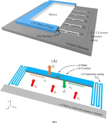
The new MEMS-based low voltage Lorentz force deformable mirror (DM) system is composed of a 20 × 20 Lorentz actuators array and a flexible silicon nitride or epoxy-based mirror bonded to the top of the actuator substrate formed on crystalline silicon using a microfabrication process (See Figure 1A). The technical specification for applying the DM in the TMT considered in the design is 10 µm stroke, less than 1 ˚C temperature variation, 10 to 40 % inter-actuator coupling, and over 800 Hz bandwidth.
(A)
(B)
Figure 1. Illustration of a 5 × 5 array of Lorentz actuators with mirror attached DM (A), and a Lorentz force actuator with working principle (B).
The horseshoe-shaped Lorentz actuator is comprised of a central thick and rigid crossbar supported by two flexible serpentine springs on either side that are clamped to the wafer-thick rail (300 µm), as shown in Figure 1B. The Lorentz force generated in both the top and bottom direction corresponds to the current direction on the crossbar. The Lorentz force can be computed by using Eq. 1, which relates the magnetic flux (𝐵⃗ ), current (𝑖 ), and length (L) of the crossbar;
𝑭
⃗⃗ = 𝒊 𝑳 × 𝑩⃗⃗ Eq. 1
For the scaled-up version of the 20 × 20 actuator array DM, the various mechanical and thermal properties of the actuators and mirror are simulated using COMSOL
Multiphysics software. The simulation starts by computing the inter-actuator coupling of the mirror according to the spring constant of the Lorentz actuator consisting of crystalline silicon. A total of 10 µm mirror deformation is targeted, and the maximum force to reach this deflection is calculated for both SU-8 and silicon nitride membranes. Finally, the Lorentz actuator and mirror design were refined by considering the Joule heating magnitude (less than 1 K is required for the telescope application).
3. Simulation
3.1. Deformable Mirror
Solid mechanics in the Structural Mechanics Module of COMSOL Multiphysics 5.4 was used for simulations. Figure 2 shows the boundary conditions for all four sides of the clamped continuous membrane. The model consists of a 5 × 5 spring foundation array with 2 mm actuator pitch beneath a continuous membrane. The spring foundation is a virtual boundary that replaces a complex spring structure and acts as an elastic or damping boundary. The spring boundaries are used as actuator nodes of mechanically bonded actuators through a pillar. Therefore, various performances of the DM system, such as inter-actuator coupling, spring constant, and operation current, can be evaluated by adjusting the elasticity of the spring foundation. The membrane consists of 4 µm thick SU-8 and 0.5 µm thick silicon nitride. Each thickness is defined based on the microfabrication limit of both free-standing films. The 150 nm Aluminum mirror layers on both sides of the membrane were not included due to the small thickness that will have negligible mechanical properties compared to the membrane.
Figure 2. Boundary conditions of the SU-8 and silicon nitride membranes with spring foundation.
Epoxy-based negative tone photoresist SU-8 and silicon nitride are selected as the materials for the mirror
membrane, due to their relatively low Young's modulus, smooth surfaces, and compatibility with the semiconductor fabrication processes. Some essential material properties used in the simulation are listed in Table 1.
Table 1. Thermal and mechanical properties of SU-8 and silicon nitride.
Items SU-8 Silicon
nitride Young's Modulus (GPa) 2 160 Density (g/cm3) 1.22 3.18
Thermal conductivity (W/mK) 0.3 20 CTE (10-6 m/K) 50 2.3
As a first simulation, the actuator spring constant on the spring foundation was varied from 0 to infinite (clamped). Here, clamping means that there is no translation or rotation permitted (x = 0, y = 0, z = 0). Figure 3A and B show plots of displacement versus distance from the central actuator for a 4 µm thick SU-8 and 0.5 µm silicon nitride membrane as a function of actuator spring constant. In these plots, the force is loaded at point "a" in Figure 2. From these results, we can determine that the Silicon nitride film shows more dramatic strain change compare to the epoxy membrane. The thick SU-8 film has a lower density than the silicon nitride film, so the strain caused by loading can be diffused more easily than the silicon nitride. The results also show that SU-8 is better suited for applications requiring a large stroke. However, SU-8 is thermally unstable and has more restrictions in microfabrication and operation than silicon nitride. Therefore, in this study, a new scaled up DM is studied using both materials.
(A) 4 µm SU-8
(B) 0.5 µm Silicon nitride
Figure 3. 5 µm deformation profile of 4 µm SU-8 membrane (A), and 0.5 µm silicon nitride membrane with various spring constants of the actuators.
Figure 4. SU-8 and silicon nitride membrane inter-actuator coupling versus spring constant of the actuator. Regions labelled (A) and (B) show the spring constant of an actuator (Ka) to have an appropriate
inter-actuator coupling.
Figure 4 shows the inter-actuator coupling changes of SU-8 and silicon nitride membranes as a function of actuator spring constant (Ka). The DM requires a coupling
of less than 10 % to 40%, depending on the application. This simulation was limited to less than 1 N/m spring constant due to the high current resulting from higher values and the consequent increases in system temperature. As observed in Figure 4, the spring constant of the actuator is inversely proportional to the inter-actuator coupling of the mirror. The available spring constant of the actuators of each different membrane that
will satisfy the requirements for 10 - 40% coupling is indicated by the regions labelled A and B. Section 3.2 finds appropriate actuator spring constant to minimize the heat caused by Joule heating and the Lorentz force required to deform the mirror within these two regions.
3.2. Actuator optimization
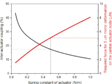
The actuator spring constant of the DM can now be studied by computing the required Lorentz force for ± 5 µm mirror deformation. In Figure 5, the force needed for 5 µm deformation corresponding to the spring constant of the actuator was found using COMSOL Multiphysics simulation and is indicated by the solid red curve. As shown in the figure, a 0.5 N/m actuator attached to a 0.5 µm thick silicon nitride DM requires 5 µN for 5 µm deformation, and inter-actuator coupling is expected to be about 17 %. A 4 µm SU-8 mirror requires 4.7 µN force in the same condition and shows about 35% inter-actuator coupling. A more rigid inter-actuator requires more force to deform a membrane, but increases the resonant frequency of the DM. On the other hand, softer actuators reduce the operation power, but give higher mechanical crosstalk on the membrane. The simulation result for the silicon nitride mirror is not presented in this paper to reduce redundancy.
Figure 5 Inter-actuator coupling and loading force from the actuator for 4 µm thick silicon nitride membrane DM
With the optimized actuator spring constant now known, the spring dimension is determined to ensure adequate electrothermal performance and microfabrication feasibility. A 3D model, as shown in Figure 1B, was built onto the COMSOL Multiphysics software. The structural material is crystalline silicon, mainly used in the microfabrication process and can be found in the material library. The crossbar dimension was determined as 1640 µm length, 200 µm width, and 25 µm thickness in the same way in the paper published at COMSOL 2015 conference, Boston [6]. Therefore, the design of MEMS Lorentz DM is completed with the dimension of the serpentine spring that defines the spring constant and temperature characteristics of the actuator.
Various lengths and thicknesses with a 40 µm width serpentine spring were considered that can be deformed by an applied force on the thick crossbar. Figure 6 shows the
calculation results for various serpentine spring dimensions. As shown in the figure, the rail becomes too thin to support the actuator and mirror sufficiently when the spring is longer than 4300 µm. In addition, using KOH bulk micromachining, it is challenging to leave less than 4 µm thick spring structures. Furthermore, the pink coloured area shows where the spring will be too rigid. Therefore, the appropriate spring thickness and length are presented with a light green colour (surrounded by a blue triangle) in the figure. In this region, the applicable spring length can arbitrarily set to 3700 µm, and the rail width determined as 560 um.
Figure 6. Design map determines the spring dimension of the actuator.
Finally, the suitable spring thickness was determined to be 6 µm, as shown in the blue dotted line in Figure 6. This is the result of considering the spring constant and temperature characteristics simultaneously. For the desired 5 µm motion, around 5 µN force is needed. This force corresponds to a 9 mA current flowing in the crossbar with a 0.3 Tesla magnetic field from Eq. 1. Referring to Figure 7, we can see that less than 1 K temperature change can be found for over 6 µm thick springs. It should be noted that the same performance can be achieved at a lower current of 5.5 mA and 4 mA in a stronger magnetic field of 0.5 Tesla or 0.7 Tesla, respectively.
4. Conclusions
In this paper, a newly designed MEMS-based Lorentz actuator is presented due to the scale-up from 5 × 5 to 20 × 20 actuator array. The mechanical inter-actuator coupling of both SU-8 and silicon nitride DM was successfully simulated. The c-Si based Lorentz actuator that satisfies a 10 to 40 % inter-actuator coupling of DM, a large stroke of a total 10 µm with 2 mm actuator pitch, was successfully designed. In addition, this design suppresses the heat caused by Joule heating to less than 1 K. The designed MEMS-based Lorentz DM offers lower voltage operation compared to conventional electrostatic DMs.
Figure 7. Maximum temperature change on the center of the crossbar corresponds to a current of various thicknesses of actuator spring.
References
[1] R. K. Tyson, Principles of Adaptive Optics. CRC Press, New York, 2015.
[2] H. Kaushal and G. Kaddoum, "Optical Communication in Space: Challenges and Mitigation Techniques," IEEE Communications Surveys Tutorials, vol. 19, no. 1, pp. 57–96, 2017, doi: 10.1109/COMST.2016.2603518. Kaushal, H., & Kaddoum, G. Optical Communication in Space: Challenges and Mitigation Techniques. IEEE Communications Surveys &
Tutorials, 19(1), 57–96(2017)
https://doi.org/10.1109/COMST.2016.2603518
[3] S. D. Senturia, Microsystem Design. Springer Science & Business Media, New York, 2007.
[4] K. Banerjee, P. Rajaeipour, H. Zappe, and Ç. Ataman, "A 37-actuator polyimide deformable mirror with electrostatic actuation for adaptive optics microscopy," J. Micromech. Microeng., vol. 29, no. 8, p. 085005, Jun. 2019, doi: 10.1088/1361-6439/ab2370.
[5] B. Park, E. Afsharipour, D. Chrusch, C. Shafai, D. Andersen, and G. Burley, "Large displacement bi-directional out-of-plane Lorentz actuator array for surface manipulation," J. Micromech. Microeng., vol. 27, no. 8, p. 085005, Jul. 2017, doi: 10.1088/1361-6439/aa7970.
[6] B. Park, T. Chen, C. Shafai, "Design and Simulation of A MEMS Based Horseshoe Shaped Low Current Lorentz Deformable Mirror (LCL-DM)." COMSOL
2015 conference, Boston, 2015.
[7] B. Park, E. Afsharipour, D. Chrusch, C. Shafai, D. Andersen, and G. Burley, "A low voltage and large stroke Lorentz force continuous deformable polymer mirror for wavefront control," Sensors and Actuators A:
Physical, vol. 280, pp. 197–204, Sep. 2018, doi:
10.1016/j.sna.2018.07.047.
[8] G. Herriot et al., "NFIRAOS: TMT narrow field near-infrared facility adaptive optics," in Advances in
Adaptive Optics II, Jun. 2006, vol. 6272, p. 62720Q,