HAL Id: hal-01994606
https://hal.insa-toulouse.fr/hal-01994606
Submitted on 22 May 2019
HAL is a multi-disciplinary open access archive for the deposit and dissemination of sci-entific research documents, whether they are pub-lished or not. The documents may come from teaching and research institutions in France or abroad, or from public or private research centers.
L’archive ouverte pluridisciplinaire HAL, est destinée au dépôt et à la diffusion de documents scientifiques de niveau recherche, publiés ou non, émanant des établissements d’enseignement et de recherche français ou étrangers, des laboratoires publics ou privés.
Tuning Deposition of Magnetic Metallic Nanoparticles
from Periodic Pattern to Thin Film Entrainment by Dip
Coating Method
Julien Dugay, Reasmey Phary Tan, Anais Loubat, Lise-Marie Lacroix, Julian
Carrey, Pier-Francesco Fazzini, Bruno Chaudret, Marc Respaud
To cite this version:
Julien Dugay, Reasmey Phary Tan, Anais Loubat, Lise-Marie Lacroix, Julian Carrey, et al.. Tuning Deposition of Magnetic Metallic Nanoparticles from Periodic Pattern to Thin Film Entrainment by Dip Coating Method. Langmuir, American Chemical Society, 2014, 30 (30), pp.9028-9035. �hal-01994606�
Tuning Deposition of Magnetic Metallic
Nanoparticles from Periodic Pattern to Thin Film
Entrainment by Dip Coating Method
J.Dugay,
∗R.P.Tan, A.Loubat, L.-M. Lacroix, J.Carrey,
∗Pier F. Fazzini, B.Chaudret,
and M.Respaud
Laboratoire de Physique et Chimie des Nano-Objets, Université de Toulouse; INSA, UPS, 135, av. de Rangueil, F-31077 Toulouse, France CNRS; LPCNO, F-31077 Toulouse, France
E-mail: julien.dugay@gmail.com;julian.carrey@insa-toulouse.fr
Abstract
In this paper, we report the self-assembly of chemically synthesized metallic CoFe nanoparti-cles (NPs) from periodic pattern to thin film. NPs depositions were carried out inside a coupled glovebox-sputtering system to prevent NP oxidation and to tune the surface energy of the substrate through oxygen plasma treatment. A home-made dip coating setup allowing the vertical withdrawal of substrate from the colloidal suspension was used. We have systematically investigated the effects of NP concentration, withdrawal speed, nature (amino and acid groups) and amount of surfactants in suspension on the quality of the deposit on hydrophilic substrates (SiO2 or Au). The stripe
thickness, width and spacing, formed by the deposit, can be controlled by the NP concentration and the withdrawal speed. The surfactant concentration generally tends to decrease the NP coverage, except for amine which induced an improved coverage on silica substrate. We report here for the first time that dip coating is a suitable and reproducible technique to deposit magnetic metallic NPs over large areas from stripes pattern to thin films entrainment.
Introduction
Self-assembly is a physical concept present in Na-ture from atomic scale to large-scale strucNa-tures of the universe. Such phenomenon can be de-fined as the self-assembly of similar entities in patterns or structures, without any human inter-vention, but in a controlled environment.1 Nowa-days, the recent developments in colloidal syn-thesis allows the growth and the self-assembly of artificial nanometer-scale metallic, semiconductor, and/or magnetic building blocks thanks to a fine tuning of NP morphological characteristic such as size, size-distribution and aspect ratio, and their physico-chemical properties governed by capping surfactants.2
Thanks to these unprecedented properties, mag-netic NPs (MNPs) may be used for spintronics devices applications.3,4For instance a new type of magnetoresistance5 and tunneling magnetoresis-tance (TMR) up to room temperature6 have been recently observed in MNPs surrounded by organic ligands.
However, a crucial issue for such applications is the perfect control of MNPs deposit directly onto prefabricated electrodes in form of chains, arrays, and networks.7Such a control would allow on one hand, to tune the strength of the dipolar interac-tions between MNPs and thus increase the ampli-tude of the TMR.8 We emphasize that to observe TMR in MNPs assemblies, drastic precautions against oxidation need to be taken.6 On the other
hand, the control could also permits to study the influence of dimensionality and structural disorder on transport mechanism and therefore on the re-sulting magneto-transport properties.9,10
One way to integrate the NPs into patterned de-vices is based on physical and/or chemical tem-plates, obtained by lithography,11,12 microcontact printing,13–16 micro-injection molding in capillar-ies,17 dip pen lithography,18,19 elimination lithog-raphy on self-assembled monolayers20 or a com-bination of such approaches.21,22
Nevertheless, the one-step self-assembly of NPs on solid substrates directly from colloidal solu-tion is highly desirable. To date, several strate-gies have been developed: drop-casting of NP suspension on solid substrates23,24 or at the sur-face of an immiscible polar organic subphase,25,26 langmuir-blodgett method,27,28convective-self as-sembly29,30 or spin coating.31
In spite of extensive efforts, a direct deposition of NPs on solid surfaces with controlled arrange-ments - from stripes pattern to thin film entrain-ment - with tunable spacing, thickness and or-ganization remains a challenge, especially when metallic magnetic nano-objects are involved. In-deed, to prevent NP from oxidation, the deposition based on polar organic subphase should be avoided while the atmosphere should be strictly controlled. Glovebox could enable such a control, however, space limitation and handling difficulty arisen. To our knowledge, no report on a controlled deposit method compatible with the metallic character of magnetic NPs assembly has been reported so far. MNPs can be synthesized following various method,32 one of which being the organometal-lic approach, which consists in the decomposition of a metal complex thanks to a reducing agent under mild conditions in presence of organic sur-factants.33The final MNP is surrounded by surfac-tants which prevent their aggregation and ensure their stabilization in organic solvents with fairly low polarity.34 An excess amount of surfactants is usually needed to insure the stabilization of the colloidal solution, thus, the uncoordinated surfac-tants can interact with the substrate and modify the morphology of the deposits.35The surfactants also affect the suspension properties such as evap-oration rate, surface tension and colloidal/self-assembly behavior. The exact composition of the
solution (amount and nature of surfactants) vary-ing slightly with the synthesis, the detailed study of the influence of deposit parameter must be per-formed on the very same MNP batch.
Here we present the self-assembly of chemically synthesized metallic CoFe MNPs carried out with a home-made dip coating setup placed directly in-side a coupled glovebox-sputtering system. Such a configuration preserves the good properties of the MNPs during the deposition while permitting the modulation of the interfacial energy of the sub-strates by oxygen plasma treatment. CoFe MNPs were synthesized by an organometallic approach in presence of amine and acid as surfactants. High yield and reproducibility were obtained. Such fea-tures permit to perform several experiments with the same batch in order to figure out the impact of the different key parameters. MNP concen-tration, withdrawal speed, nature and amount of surfactants in suspension and substrate surface state have a strong influence on the self-assembly process and allow controlling the nature of the deposit from stripes to thin film entrainment.
Experimental Section
Materials and Methods
Chemicals and materials. Chemicals and ma-terials. All syntheses were prepared and puri-fied under argon or dihydrogen using Fischer-Porter bottles techniques, a glove box and ar-gon/vacuum lines. Mesithylene (99 %), tetrahy-drofurane (THF, 99 %), were purchased from VWR Prolabo and distilled and degassed through three freeze-pump-thaw cycles. Hexadecylamine (HDA, 99 %), oleic acid (OA, 99 %) and stearic acid (SA, 99 %), were purchased from Sigma-Aldrich, iron(0)pentacarbonyl (Fe(CO)5,
99,5%) from Acros organics and cyclooctadiene-cyclooctenyl (Co(η3− C8H13)(η4− C8H12), 99
%) from Nanomeps and used as received.
Fabrication and preparation of the substrates. Standard photolithography was used to make gold electrodes (5 nm Ti/30 nm Au) on 0.25 cm2 squares silicon wafers covered by a 300 nm layer
of thermally grown silica (SiO2). Resina layer
used to protect the substrates was removed with acetone, ethanol and deionized water and dried un-der nitrogen flow. UV ozone treatment of 15 min render them hydrophilic prior to their introduction in the glove box.
The surface wettability was characterized by con-tact angle measurements performed at room tem-perature with a GBX Digidrop. Each contact an-gle represents an average value of three measure-ments on different sample areas. Oxygen plasma could be used to modulate the surface energy of substrates stocked at least one day in advance in the glovebox, using a MP450s Plassys system cou-pled to the glove box. The working pressure was maintained at 8 mTorr, and a flow rate of 4 and 20 sccm respectively for argon and oxygen has been used with under 10W RF power.
Synthesis and characterization of CoFe MNPs. Core/shell carbide CoFe MNPs were prepared ac-cording to a modified published procedure.36 In brief, Co(η3− C
8H13)(η4− C8H12) (1 mmole,
278 mg) was mixed with amine (HDA, 1 mmole, 242 mg) and acids (SA, 1 mmole, and OA, 1 mmole) in 10mL of Mesitylene. The reaction was stirred magnetically for 10 min. Fe(CO)5 (2
mmole, 280µL) was then injected and 40 mL of Mesitylene added. The reaction is pressurized un-der 3 bars of dihydrogen and let to react at 150 °C for 48h. To remove excess surfactants, three washing process and magnetic separation using mesitylene were used, the NP solution was then evaporated under vacuum to get a dried powder.
A droplet of a colloidal suspension of CoFe MNPs was deposited inside a glovebox on cov-ered holey copper grids. The latters were then characterized by TEM (transmission electron microscopy), HRTEM (high-resolution TEM), STEM-HAADF (scanning transmission electron microscopy using a high angle annular dark field detector) and EELS (electron energy loss spec-troscopy). XRD (X-ray diffraction) and Möss-bauer spectroscopy were carried out on a powder of CoFe MNPs that were prepared and sealed un-der an argon atmosphere.
TEM image (see Figure S1) of the MNPs was recorded with a JEOL-JEM 1011F, operating at
100 kV. The polydispersity in size was calculated from the size measurements of more than 2000 NPs using ImageJ software.37
STEM-HAADF observations (see Figure S2 (a-b) and EELS analysis (c)) were carried out at the LMA laboratory in Zaragoza, using a Cs corrected Titan Microscope equipped with an XFEG source. XRD measurements (see Figure S2 (d)) were per-formed on a PANalytical Empyrean diffractometer using Co-Kα radiation at 45 KV and 40 mA. The iron state and its environment (see Figure S3) were analyzed by Mössbauer spectroscopy (WIS-SEL, 57Co source).
Deposit of CoFe MNPs. Every steps were per-formed in the coupled glovebox-sputtering system under inert gas (Ar) to prevent NPs from oxida-tion. The MNPs were redispersed in Tetrahydro-furane (THF), solvent suitable for dip-coating de-posit thanks to its low boiling point (66° C38)39 and surface tension (28.10−3 N.m38).40Colloidal solution with desired concentration were obtained from MNP powder diluted in the appropriate vol-ume of solvent under ultrasonic bath (15 min, 40° C).
(a) (b) (c)
Figure 1: (a) Sketch of the home-made dip coating
setup used in this work(b). Schematic drawing of the
situation at the beginning of the dip-coating process.(c)
Schematic representation of MNPs accumulation and the flow pattern when the substrate is removed from the suspension.
Dip-coating experiments were performed using the home-made setup shown in Figure1. The sub-strate is maintained with a small amount of vac-uum grease on a cover slip. Such configuration enables an easy handling and prevents any de-posit on the substrate backside, altering magnetic measurements performed on the final device. The
cover slip is maintained vertically using a self grip tweezer. The first step consists in completely im-mersing the substrate in a 1 mL teflon beaker filled beforehand with the suspension of MNPs. The substrate is then withdrawn vertically at a constant speed by action of a stepper motor at a speed rang-ing from 13 µm.s−1 to 660 µm.s−1.
Characterization of assemblies. Deposit pat-terns formed by the MNPs were imaged by opti-cal microscope (Olympus BXFM) equipped with a CCD camera (Olympus DP20) integrated in the glove-box. Field emission gun scanning electron microscopy (SEM-FEG Hitachi S-4800) was per-formed at 30 KV. Topographical imaging of films was performed in tapping mode at room tempera-ture with a Digital Instruments/Veeco Dimension 3100 Atomic Force Microscope using Si tips (fre-quency range: 240-380 kHz, Force: 42 N.m−1). AFM image processing and rendering was ana-lyzed with WsXM data analysis software.41 The magnetic properties of assemblies were inves-tigated by using a superconducting quantum in-terference device (SQUID) magnetometer MPMS XL SQUID (7 T). Magnetization versus applied magnetic field curves were recorded at 2K without applying any magnetic field referred as ZFC (Zero field cooling). Then, the field cooling curves (FC) were recorded after the temperature was set down 2 K under 5 T. The substrates containing the as-semblies of MNPs were placed in a parallel direc-tion to the one of the applied magnetic field.
Results and discussions
Results
Core/shell carbide CoFe MNPs used hereafter ex-hibit a polydisperse size distribution with a diam-eter centered on 25.4 ± 9.7 nm and 14 ± 4 nm separated by organic ligands with a thickness dis-tribution centered on 2.3 ± 1 nm (see Figure S1). STEM-HAADF images highlighted the polycrys-talline morphology of the CoFe MNPs (see Figure S2 (a-b)) while STEM-EELS analysis evidenced a core-shell structure (respectively Co/Fe). It will be noted that the shell (see orange color in Figure S2 (c)) is very thin compared to the core. XRD
mea-surements, used to characterize the phases present in a powder of CoFe MNPs, revealed that the crys-tallization of the core is a ε cobalt phase while the signature of Fe could be masked by the small size of crystallites and the strong signal of cobalt. Such unexpected phase suggests the presence of carbon formed during the synthesis, and its diffusion in-side the MNPs structure confirmed by Mossbauer spectroscopy showing a carbide phase following a stoichiometry of Fe1−xCoxCy(see figure S3).
A powder sample exhibited a weak ferromag-netism character at 200 K as determined by SQUID magnetometry (MS = 140 A.m2.kg−1,
and HC = 6 mT). The fact that the mean magne-tization at saturation is below the expected value (MS bulk = 174 A.m2.kg−1) could be related to
the presence of carbon inside the MNPs structure and/or carbon monoxide on the surfaces of the lat-ters. The absence of a shift of the coercive field at 2 K after ZFC and FC (see Figure S4) confirms that the MNPs are not oxidized after synthesis. MNPs concentration
We investigated the effect of the concentration of the CoFe MNP suspension on the deposit pattern. The concentration was varied from [5 mmol.L−1] to [50 mmol.L −1]. The minimum value was lim-ited by the accuracy of the microbalance giving an error around 15 %, while the highest concentration was the threshold above which the MNPs were not effectively stabilized in the solvent. Except for the highest concentration, colloidal solution were sta-ble for several hours, much longer than dip coating experiments (≈ 6 min per deposit).
Figure 2 (a) depicts optical images of four deposits obtained respectively for 5, 10, 20 and 50 mmol.L−1 at a fixed withdrawal speed (13 µm.s−1). Corresponding scanning electron microscopy (SEM) images taken in random ar-eas are shown in Figure S5. Formation of stripe patterned layer, perpendicular to the withdrawal direction (horizontal on the images) was observed for each sample. The width and spacing of the stripes could be monotonically tuned by the con-centration of the CoFe MNP suspensions as evi-denced in Figure 2 (b). We observed an increase of the averaged width as well as the stripes spacing
0 10 20 30 40 50 0.0 0.5 1.0 1.5 2.0 2.5 3.0 3.5 4.0 On stripes Between stripes
5 mmol/L
10 mmol/L
20 mmol/L
50 mmol/L
(a)
(b)
(c)
200 µm 200 µm 200 µm 200 µm 0 10 20 30 40 50 0 10 20 30 40 50 60 70 80 90 100 spacing width Concentration (mmol.L-1) Spacing / Width (µm) Concentration (mmol.L-1) Number of layers Concentration (mmol.L-1) MNPs coverage (%)(d)
0 10 20 30 40 50 10 20 30 40 50 60 70 80 90 100 On stripes Between stripesFigure 2: (a) Optical images of the stripe patterns formed perpendicularly to the withdrawal direction on the silicon
oxide and gold electrodes. All deposits were performed at constant withdrawal speed (13 µm.s−1) for different MNP concentration: 5, 10, 20 and[50 mmol.L−1].(b) Summary of the averaged width of the stripes (red triangles) and the
average spacing between the consecutive stripes (black circles). The error bars correspond to statistical dispersion of the measurements performed on the entire surface of the substrates. (c)-(d) Summary of respectively the mean
number of layers and the MNP coverage (deduced from AFM measurements) as a function of the concentration.
when the MNP concentration increases, similarly to what can be found in the literature.42Thickness of the deposit, quantified in number of layers, was evaluated from AFM images both on stripes or in between, depicted respectively in black or red in Figure S6.
For the lowest MNP concentration (see the Fig-ure S6 (a)), thickness of a quarter of a layer was detected, corresponding to the substrate roughness between stripes, thus, no MNPs deposit. This roughness must be removed from further quan-titative analysis. To further quantify the results obtained, two parameters were introduced i) the mean number of layers ¯NL(Figure2c)) which can be quantified by: ¯ NL = Z N L× Ptot(NL) Ptot(NL) dNL (1) and ii) the MNP coverage Γ (Figure2d)) corre-sponding to: Γ = Z P MNP(NL) Ptot(NL) dNL× 100% (2)
where NL, PMNP(NL) and Ptot(NL) are
respec-tively the distribution of the number of layers, the probability corresponding to the distribution of the number of layers without the peak correspond-ing to the substrate roughness (i.e the absence of MNPs) and the probability of the entire distribu-tion.
The mean number of layers increases with the MNP concentration both within or in between stripes, respectively black and red symbols. A plateau seems to appear for stripes of 3.5 lay-ers above [20 mmol.L−1]. In agreement, the MNP coverage evolves toward a dense deposit (100% coverage) at high concentration. Above [50 mmol.L−1], dense layer could be deposited but stripes were composed of multilayers (3 to 4). The almost linear increase of the mean number of layers (for the three lowest concentration) as well
as a high and almost constant MNP coverage are in perfect agreement with the literature.21,43 The deviation observed at the highest concentration, could be understood by the unstable character of the colloidal suspension, the actual concentration of suspended MNPs being lower than the calcu-lated one. Another hypothesis would be that, since the static contact angle formed by a droplet of THF on our substrates is very low (≈ 7 °), the thickness of the stripes is limited at high concentration by the dynamic contact angle. This could clear up why the thickness saturates while the width of the stripes still growths.
In the seeking of an homogeneous monolayer de-position, consisting of a mean thickness of one, both on and between stripes with a high MNP coverage, the best compromise was obtained for a [10 mmol.L−1] concentration. This concentration was kept constant for the rest of the study.
Withdrawal speed
We have studied the impact of withdrawal speed on the deposit properties. Experiments have been performed for [10 mmol.L−1] concentration at re-spectively 0, corresponding to the natural evapora-tion of the MNP soluevapora-tion,13, 15, 19, 29 and 180 µ m.s−1. Except for the highest withdrawal speed, which exhibited clusters of a few isolated MNPs induced by the strong stretching of the menis-cus,44 stripe patterned layer perpendicular to the withdrawal direction were detected from optical and SEM images (Figure 3 (a)), similarly to the MNP concentration study.
Figure 3 (b) summarizes the evolution of the width and the spacing of the stripes (respectively black squares and red triangles). The stripe width decreased exponentially with withdrawal speed, as previously reported.44 Concerning the spacing of the stripes, previous works have shown two behav-iors. On one hand, an almost constant spacing with the withdrawal speed (measured for a speed below ≈ 3 µm.s−1 )42,44 have been recently reported. On the other hand, a non-monotonous behaviour against the withdrawal speed was exhibited on a broader range (below ≈ 150 µm.s−1).45 The fast withdrawal induced a shorter accumulation time of MNPs at the contact line, resulting in thinner stripes. As expected, mean number of layers
de-creased also drastically both in and between stripes (Figure3(c)) as well as the density of the deposit, evaluated by the MNP coverage parameter (Figure
4and Supplementary Figure S7). Stripe width and thickness and MNP coverage evolved similarly to-wards a diminution for higher withdrawal speed. However, transition could be observed from an "evaporation" regime at low speed, with large and thick stripes, to an "intermediate regime", with a weak dependence of the stripe width with with-drawal speed associated to a low thickness.40,46,47
Withdrawal speed (µm.s
-1)
MNPs coverage (%)
1 10 100 0 20 40 60 80 100Figure 4: Evolution against the withdrawal speed of the MNP coverage deduced from AFM measurements (see Figure S7). Black (red) curves represent MNP coverage on (between) stripes.
Figure 4 shows the evolution of the MNP cov-erage on and between stripes (respectively black and red curves) deduced from AFM measurements against the withdrawal speed (see Figure S7) using Equ.(2) and the methodology described in the pre-vious part. The MNP coverage presents both on and between stripes a monotonous decrease with increasing withdrawal speed.
13 µm.s−1 speed appeared as the best compro-mise to control the deposit thickness, close to a monolayer in and between stripes, while providing the best MNP coverage (65 %). This withdrawal speed will be kept constant for the rest of the study.
Surfactants concentration
The impact of surfactants was systematically studied through the controlled addition of amine
(a)
500 µm 500 µm 500 µm 1 µm 1 µm 2 µm v = 180 µm.s-1 v = 13 µm.s-1 v = 0 µm.s-1 0.1 1 10 100 0 1 2 3 4 5 0 10 20 30 40 50 60 70 80 Largeur / espacement (um ) Withdrawal speed (µm.s-1) Spacing / Width (µm) Number of layers (Z)(b)
(c)
Figure 3:(a) Representative images of the stripes obtained by the dip coating method at different withdrawal speeds
(vertically downwards, at zero withdrawal speed (corresponding to the natural evaporation of the MNP suspension),
13 µm.s−1 and 180 µm.s−1). MNP concentration was ([10 mmol.L−1]). The left column corresponds to optical images. The right column shows SEM images of a zone located on the silica layer between two consecutive stripes.
(b) Evolution of the spacing (black squares) and the width (red triangles) of consecutive stripes with the withdrawal
speed. Error bars correspond to the statistical dispersion of measurements performed on all of the substrate (5 mm).
(c) Evolution of the mean number of layers of the stripes against the withdrawal speed. Black (red) curves represent
the mean MNP coverage on (between) stripes.
(hexadecylamine HDA) or acid (oleic acid -OA). The chemical affinities of surfactants with silica substrate or gold electrodes was investi-gated by immersing substrates separately into [10 mmol.L−1] solution of OA and HDA in THF (Figure S8). While a reference sample in THF reveals an homogeneous contrast (Figure S8 (c)), the presence of OA (liquid at room temperature) leaded to multiple droplets randomly distributed on both silica and gold (Figure S8 (a)) while HDA (solid) was solely observed on and at the vicin-ity of gold electrodes (see Figure S8 (b)). While both amine and carboxylic groups of acid can form self-assembled monolayers on gold surfaces in low-polar solvent,48,49 the affinity of surfac-tants with silica strongly depends of the substrate pending group. Silanol (Si-OH) could form hy-drogen bonds with both surfactants, while only acid could interact with siloxane bridges (Si-O-Si), thus amine exhibit a lower reactivity towards silica
compared to acid.
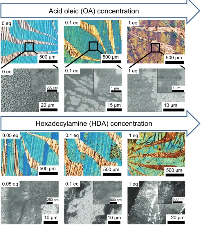
We then studied the influence of the ligand concen-tration on the MNP deposit at optimized speed (13 µ ms−1) and concentration [10 mmol.L−1]. Con-trolled concentration of surfactants (varying from 0 to [10 mmol.L−1], referred to as 1 equivalent per mole of metal, eq.) were added to the colloidal so-lution and sonicated for 15 min. Optical images revealed a clear evolution of the color of the de-posits, while SEM images addressed the deposit morphology (Figure5).
In presence of OA, MNP coverage decreased, 3D isolated islands and regions evidenced by a black contrast in SEM images, probably filled with organic molecules, arisen both on Au and SiO2
surface (Figure S8 (a)). While the same behaviour was observed in presence of HDA on Au elec-trodes, the MNP coverage on SiO2increases with
HDA (Figure5and Figure S9). Ligand physisorp-tion, enhanced at the three-phase contact line,
Acid oleic (OA) concentration
Hexadecylamine (HDA) concentration
500 µm 500 µm 500 µm 20 µm 15 µm 10 µm 0 eq 0.1 eq 1 eq 0 eq 0.1 eq 1 eq 0.05 eq 0.1 eq 1 eq 0.05 eq 0.1 eq 1 eq 20 µm 10 µm 10 µm 500 µm 500 µm 500 µm 1 µm 1 µm 250 nm 500 nm 500 nm 500 nm
Figure 5: Optical and SEM images of the deposits obtained by the dip coating method at the optimized speed (v = 13µm.s−1). The concentration of the surfactants has been varied by adding the latters in a powder form directly inside the colloidal suspensions of CoFe MNPs beforehand prepared at optimized concentrations ([X] = [10 mmol.L−1]).
Excess amount of(a) 0, 0.1 and 1 equivalent of OA and (b) 0.05, 0.1 and 1 equivalent of HDA has been added. All
SEM images are located on silica and endowed, in inset, with magnified view.
could form a shear barrier to prevent MNPs inter-action with the surface, decreasing the MNP cov-erage.35,50,51 In the case of low affinity between the surfactants and the surface, no steric hindrance
were encountered, as evidenced for HDA on SiO2.
Surfactants could enhance the MNPs-MNPs inter-actions as well as the depletion force, increasing the MNP coverage as previously reported.23,52
Surface energy of the substrates
We studied so far the deposition on silica and gold surfaces beforehand cleaned by ultraviolet (UV)/ozone and then stored inside the glove box. However, the surface state evolved as evidenced by the drastic increase of the contact angle of deionized water from 10 ◦ and reach 60 ◦ after 6 hours (Figure S10). Such evolution is proba-bly due to the physisorption of organic molecules or contaminants. To address the effect of sur-face energy and solvent wettability issue we per-formed oxygen plasma treatment of different time. Dip coating of treated substrate were performed under optimized conditions (v = 13 µm.s−1 and [X ] = [10 mmol.L−1]).
For long plasma treatment stripes were less vis-ible, suggesting that the deposition mechanism is close to a thin film entrainment (Figure 6). SEM images confirmed that MNP coverage significantly increased compared to a deposit on bare substrate (Figure S5 (b)) for comparison). Such enhance-ment of the MNP coverage could be explained by i) the removing of physisorbed molecules which, as previously discussed, decrease the interaction energy between the MNPs and the substrate,35 and/or ii) a lower contact angle, which permits a higher evaporation rate and a homogeneous thick-ness of the deposit.53
Concerning this last point, the average spac-ing between two successive stripes as well as the width of the stripes increases nonlinearly with the oxygen plasma treatment duration (Figure7). Such experiments demonstrates indirectly the de-crease of the contact angle acting on the triple line. Indeed, a smaller contact angle (for a fixed withdrawal speed) is known to avoid the MNPs to diffuse toward to the triple contact line and en-tails that the next stripe starts its formation farther (i.e the average spacing increases).54 Moreover, it has been shown that a low contact angle provide a convective self-assembly with wider stripes, while increasing contact angle progressively forms in-completely layers with defects until prevent MNPs from being deposited on the substrates when the contact angle reaches around 20 °.55
To conclude on that point, the increase of the av-erage spacing between two consecutive stripes combined to an increase of the widths constitute
Plasma time (min)
Spacing /
Width
(µm
)
0 5 10 15 20 0 10 20 30 40 50 60 70 80 90 100Figure 7: Evolution of the spacing (black circles) and the width (red triangles) of consecutive stripes against the oxygen plasma treatment for different exposition dura-tions. The first point (t = 0) is the reference for this study, where a substrate of the same batch was stored in the glovebox at least for one day without oxygen plasma treatment. Error bars correspond to the statistical dis-persion of measurements performed on all the substrate (5 mm).
a fingerprint of the decrease of the contact an-gle when the oxygen plasma treatment duration is longer.
The intrinsic magnetic character of the CoFe MNPs used in this work could also be an im-portant factor guiding the self-assembly through magnetostatic dipole-dipole interactions (U). In particular, it has been shown that, for U > 8 kBT,
characteristic and noticeable self-organizations of MNPs are observed (rings, chains, ...56). In our case, one can estimate the dipolar energy between two MNPs i and j using U ≈ (µiµj)/σi, j3 where
µi= MsVi is the magnetization carried by a MNP
i of volume Vi and σi, j the center-to-center
dis-tance between the MNPs i and j. Due to the bidisperse character of the MNPs (displayed on their size distribution in Figure S1), we obtain U ≈ 124 and 316 kBT for the small and the larges MNPs respectively. Despite these large values of (U >> kBT), we never clearly observed the
char-acteristic structures induced by a self-assembly governed by dipolar interactions.56
In fact, many theoretical works demonstrated that the probability of forming MNPs chains are strongly reduced in bimodal systems compared
500 µm
t = 2 min t = 5 min t = 20 min
500 µm
10 µm t = 20 min
1 µm
500 µm
Figure 6: Optical images of samples deposited after different oxygen plasma treatment durations : 2 min, 5 min and 20 min respectively from the left to the right. Other conditions arev = 13µm.s−1 and[X] = [ 10mmol.L−1]). On the bottom, high resolution SEM images located on silica for the longest plasma treatment are shown.
to monodisperse ones.57–59 This can be quali-tatively explained by the presence of the small MNPs which i/ lowered the effective dipolar inter-actions seen by the larges MNPs, and ii/ increase the breakup probability of long chains through their Brownian motion; both phenomena leading to only 2-3 MNPs aggregation.
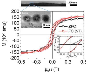
Finally, magnetic measurements have been per-formed on a deposit of CoFe MNPs using the optimized conditions described above (speed 13 µm.s−1, concentration 10 mmol.L−1 on a sil-icon substrate with native thin oxide cleaned by plasma oxygen during 20 min). To preserve the magnetic properties of the MNPs, but also their geometrical arrangement after dip-coating, a thin resin layer (≈ 40 nm thick) has been deposited followed by four annealing steps (1 min at 90°, 110°, 170°, 250°), still inside the glovebox (see Figure8). The magnetic measurements have been performed with the magnetic field applied in the plane of the substrate. Interestingly, the hysteresis
loops measured at 2 K after field cooling under 5 T did not exhibit any exchange bias features, meaning that no oxidation occurred during the whole process, i.e the magnetic properties of the MNPs are preserved. It will be noted that this deposition method was successfully extended to MNPs displaying monodisperse size distribution for different materials, ligands and to various type of substrates. These latter works will be reported elsewhere.
Outline
In conclusion, we have systematically investigated the influence of MNP concentration, withdrawal speed, nature/concentration of the surfactants and the surface state of the substrates on the deposit obtained by dip-coating technique. We success-fully performed deposition of metallic magnetic MNPs on hydrophilic surfaces under inert atmo-sphere thanks to an home-made set-up designed in a couple glovebox-sputtering system, to prevent
-0.5
-0.3
0.0
0.3
0.5
-200
-150
-100
-50
0
50
100
150
200
ZFC FC (5T)10
-5e
.m.u
-30 -20 -10 0 10 20 30 -60 -40 -20 0 20 40 60 10 -5 e .m.u!
"!"#$%&
!"!"#'$%& (b) µ 0H (T) M (10 -5 emu)-0.5
-0.3
0.0
0.3
0.5
-200
-150
-100
-50
0
50
100
150
200
ZFC FC (5T)10
-5e
.m.u
20 nm µ0H (T) M (10 -5 emu) 200 nm !"#$% &'()% &'% *"+',-% µ0H (mT)Figure 8: At the top, a cross section TEM picture of the sample used for the magnetic measurements. On the bottom: in-plane hysteresis loops of the sample measured at 2K after zero-field cooling (ZFC) (black squares) and after field-cooling (FC) under 5T (red cir-cles).
any oxidation of the deposit. The film thickness can be controlled by either the MNP concentra-tion or the withdrawal speed. Deposiconcentra-tion of sin-gle monolayers could be reached for a concentra-tion of [X] = [10 mmol.L−1] and a withdrawal speed v= 13µm.s−1. On contrary, very thick pe-riodic stripes can be formed either at high MNP concentration or without any withdrawal force, corresponding to the natural evaporation of the MNP suspension. By adding surfactants contain-ing amino and acid groups in two distinct freshly synthesized suspensions, we have demonstrated how drastically the nature and the amount of such surfactants modifies the morphology of the de-posit. For surfactants strongly interacting with the surface, lower MNP coverage were obtained, ph-ysisorbed surfactants acting as shearing barrier to-wards MNP adhesion. When surfactants do not ex-hibit preferential interaction, for instance for HDA on SiO2, improved coverage were obtained,
prob-ably due to the enhancement of MNPs-MNPs in-teractions and depletion force in suspension. A 20 min plasma treatment of the samples prior to dip-coating yield the highest MNP coverage.
Interestingly, those preliminary experiments per-mits to achieve dense monolayer of monodisperse
MNPs (Fe, Co, CoFe) on silica surfaces function-alized by APTES molecules, gold surfaces as well as thin resina layer while preserving the magnetic properties of the MNPs which will be published elsewhere.
Supporting Information Available
Additional experimental results are available. Structural analysis ((1) TEM, size distribution, (2) STEM-HAADF, STEM-EELS, Powder XRD patterns, (3) Mossbauer) of CoFe MNPs. (4) Magnetic properties of a powder of CoFe MNPs measured at different temperature without mag-netic field and under 5 T merely at 2 K. (5) SEM characterization taken after the deposition at dif-ferent concentration. (6-7) AFM measurements performed at different MNP concentration and withdrawal speed. (8) Optical images taken af-ter the substrates were immersed in suspensions of OA and HDA dissolved in THF as well as pure THF. (9) A high resolution SEM image located be-tween two consecutive stripes when a large excess of HDA (1 eq) were added to the suspension. (10) Evolution against the time of the contact angle of cleaned substrates and then stored in glovebox.Acknowledgement
This work was partly supported by the CNRS LAAS member of french RENATECH network. The authors gratefully acknowledge C.Nayral and F.Delpech for fruitful discussions.
References
(1) Whitesides, G. M.; Grzybowski, B. Self-Assembly at All Scales. Science 2002, 295, 2418–2421.
(2) Talapin, D. V.; Lee, J.; Kovalenko, M. V.; Shevchenko, E. V. Prospects of Colloidal Nanocrystals for Electronic and Optoelec-tronic Applications. Chemical Reviews 2010, 110, 389–458.
(3) Reiss, G.; Hütten, A. Magnetic nanoparti-cles: Applications beyond data storage. Na-ture Materials2005, 4, 725–726.
(4) Chappert, C.; Fert, A.; Van Dau, F. N. The emergence of spin electronics in data storage. Nat Mater2007, 6, 813–823.
(5) Tan, R. P.; Carrey, J.; Desvaux, C.; Grisolia, J.; Renaud, P.; Chaudret, B.; Respaud, M. Transport in Superlattices of Magnetic Nanoparticles: Coulomb Block-ade, Hysteresis, and Switching Induced by a Magnetic Field. Phys. Rev. Lett. 2007, 99, 176805.
(6) Dugay, J.; Tan, R. P.; Meffre, A.; Blon, T.; Lacroix, L.; Carrey, J.; Fazzini, P. F.; Lachaize, S.; Chaudret, B.; Respaud, M. Room-Temperature Tunnel Magnetoresis-tance in Self-Assembled Chemically Synthe-sized Metallic Iron Nanoparticles. Nano Let-ters2011, 11, 5128–5134.
(7) Koh, S. Strategies for Controlled Placement of Nanoscale Building Blocks. Nanoscale Research Letters2007, 2, 519–545.
(8) Tan, R. P.; Lee, J. S.; Cho, J. U.; Noh, S. J.; Kim, D. K.; Kim, Y. K. Numerical sim-ulations of collective magnetic properties and magnetoresistance in 2D ferromagnetic nanoparticle arrays. Journal of Physics D: Applied Physics2010, 43, 165002.
(9) Tran, T. B.; Beloborodov, I. S.; Hu, J.; Lin, X. M.; Rosenbaum, T. F.; Jaeger, H. M. Sequential tunneling and inelastic cotunnel-ing in nanoparticle arrays. Phys. Rev. B 2008, 78, 075437.
(10) Pauly, M.; Dayen, J.; Golubev, D.; Beaufrand, J.; Pichon, B. P.; Doudin, B.; Bégin-Colin, S. Co-tunneling Enhancement of the Electrical Response of Nanoparticle Networks. Small 2012, 8, 108–115.
(11) Cui, Y.; Björk, M. T.; Liddle, J. A.; Sönnich-sen, C.; Boussert, B.; Alivisatos, A. P. Inte-gration of Colloidal Nanocrystals into Litho-graphically Patterned Devices. Nano Letters 2004, 4, 1093–1098.
(12) Dai, Q.; Chen, Y.; Liu, C.; Rettner, C. T.; Holmdahl, B.; Gleixner, S.; Chung, R.; Pitera, J. W.; Cheng, J.; Nelson, A.
Programmable Nanoparticle Ensembles via High-Throughput Directed Self-Assembly. Langmuir2013,
(13) Guo, Q.; Teng, X.; Yang, H. Fabrica-tion of Magnetic FePt Patterns from Lang-muir–Blodgett Films of Platinum–Iron Ox-ide Core–Shell Nanoparticles. Advanced Ma-terials2004, 16, 1337–1341.
(14) Park, J.; Lee, W.; Bae, S.; Kim, Y. J.; Yoo, K.; Cheon, J.; Kim, S. Langmuir Monolayers of Co Nanoparticles and Their Patterning by Microcontact Printing. The Journal of Physi-cal Chemistry B2005, 109, 13119–13123. (15) Kraus, T.; Malaquin, L.; Schmid, H.;
Riess, W.; Spencer, N. D.; Wolf, H. Nanopar-ticle printing with single-parNanopar-ticle resolution. Nat Nano2007, 2, 570–576.
(16) Jie, Y.; Niskala, J. R.; Johnston-Peck, A. C.; Krommenhoek, P. J.; Tracy, J. B.; Fan, H.; You, W. Laterally patterned magnetic nanoparticles. Journal of Materials Chem-istry2012, 22, 1962.
(17) Cavallini, M.; Bystrenova, E.; Timko, M.; Koneracka, M.; Zavisova, V.; Kopcansky, P. Multiple-length-scale patterning of magnetic nanoparticles by stamp assisted deposition. Journal of Physics: Condensed Matter2008, 20, 204144.
(18) Basnar, B.; Willner, I. Dip-Pen-Nanolithographic Patterning of Metallic, Semiconductor, and Metal Oxide Nanostruc-tures on Surfaces. Small 2009, 5, 28–44. (19) Bellido, E.; Ojea-Jiménez, I.; Ghirri, A.;
Alvino, C.; Candini, A.; Puntes, V.; Af-fronte, M.; Domingo, N.; Ruiz-Molina, D. Controlled Positioning of Nanoparticles on Graphene by Noninvasive AFM Lithography. Langmuir2012, 28, 12400–12409.
(20) Krämer, S.; Fuierer, R. R.; Gorman, C. B. Scanning Probe Lithography Using Self-Assembled Monolayers. Chemical Reviews 2003, 103, 4367–4418.
(21) Fustin, C.; Glasser, G.; Spiess, H. W.; Jonas, U. Parameters Influencing the Tem-plated Growth of Colloidal Crystals on Chemically Patterned Surfaces. Langmuir 2004, 20, 9114–9123.
(22) Ma, L.; Subramanian, R.; Huang, H.; Ray, V.; Kim, C.; Koh, S. J. Electrostatic Funneling for Precise Nanoparticle Place-ment: A Route to Wafer-Scale Integration. Nano Letters2007, 7, 439–445.
(23) Bigioni, T. P.; Lin, X.; Nguyen, T. T.; Cor-win, E. I.; Witten, T. A.; Jaeger, H. M. Kinet-ically driven self assembly of highly ordered nanoparticle monolayers. Nat Mater 2006, 5, 265–270.
(24) Adachi, E.; Dimitrov, A. S.; Nagayama, K. Stripe Patterns Formed on a Glass Surface during Droplet Evaporation. Langmuir 1995, 11, 1057–1060.
(25) Dong, A.; Ye, X.; Chen, J.; Mur-ray, C. B. Two-Dimensional Binary and Ternary Nanocrystal Superlattices: The Case of Monolayers and Bilayers. Nano Letters 2011, 11, 1804–1809.
(26) Dong, A.; Chen, J.; Oh, S. J.; Koh, W.-k.; Xiu, F.; Ye, X.; Ko, D.; Wang, K. L.; Ka-gan, C. R.; Murray, C. B. Multiscale Periodic Assembly of Striped Nanocrystal Superlat-tice Films on a Liquid Surface. Nano Letters 2011, 11, 841–846.
(27) Aleksandrovic, V.; Greshnykh, D.; Rand-jelovic, I.; Frömsdorf, A.; Kornowski, A.; Roth, S. V.; Klinke, C.; Weller, H. Preparation and Electrical Properties of Cobalt-Platinum Nanoparticle Monolayers Deposited by the Langmuir-Blodgett Tech-nique. ACS Nano 2008, 2, 1123–1130. (28) Huang, J.; Kim, F.; Tao, A. R.; Connor, S.;
Yang, P. Spontaneous formation of nanopar-ticle stripe patterns through dewetting. Nat Mater2005, 4, 896–900.
(29) Bodnarchuk, M. I.; Kovalenko, M. V.; Heiss, W.; Talapin, D. V. Energetic and En-tropic Contributions to Self-Assembly of
Bi-nary Nanocrystal Superlattices: Temperature as the Structure-Directing Factor. Journal of the American Chemical Society 2010, 132, 11967–11977.
(30) Farcau, C.; Moreira, H.; Viallet, B.; Griso-lia, J.; Ressier, L. Tunable Conductive Nanoparticle Wire Arrays Fabricated by Convective Self-Assembly on Nonpatterned Substrates. ACS Nano 2010, 4, 7275–7282. (31) Johnston-Peck, A. C.; Wang, J.; Tracy, J. B.
Formation and Grain Analysis of Spin-Cast Magnetic Nanoparticle Monolayers. Lang-muir2011, 27, 5040–5046.
(32) Lu, A.; Salabas, E. L.; Schüth, F. Mag-netic Nanoparticles: Synthesis, Protection, Functionalization, and Application. Ange-wandte Chemie International Edition 2007, 46, 1222–1244.
(33) Chaudret, B. Organometallic approach to nanoparticles synthesis and self-organization. Comptes Rendus Physique 2005, 6, 117 – 131.
(34) Yin, Y.; Alivisatos, A. P. Colloidal nanocrys-tal synthesis and the organic-inorganic inter-face. Nature 2005, 437, 664–670.
(35) Kwon, C.; Yoon, T.; Yim, S.; Park, S.; Kim, K. The effect of excess surfactants on the adsorption of iron oxide nanoparti-cles during a dip-coating process. Journal of Nanoparticle Research2009, 11, 831–839. (36) Desvaux, C.; Dumestre, F.; Amiens, C.;
Respaud, M.; Lecante, P.; Snoeck, E.; Fe-jes, P.; Renaud, P.; Chaudret, B. FeCo nanoparticles from an organometallic ap-proach: synthesis, organisation and physical properties. Journal of Materials Chemistry 2009, 19, 3268–3275.
(37) Rasband, Rasband, W.S., 1997. ImageJ, U.S. National Institutes of Health, Bethesda, Maryland, USA. 1997,
(38) Smallwood, I. M. Handbook of Organic Sol-vents Halsted Press. New York 1996, 178.
(39) Jang, J.; Nam, S.; Im, K.; Hur, J.; Cha, S. N.; Kim, J.; Son, H. B.; Suh, H.; Loth, M. A.; Anthony, J. E.; Park, J.; Park, C. E.; Kim, J. M.; Kim, K. Highly Crystalline Sol-uble Acene Crystal Arrays for Organic Tran-sistors: Mechanism of Crystal Growth Dur-ing Dip-CoatDur-ing. Advanced Functional Ma-terials2012, 22, 1005–1014.
(40) Grosso, D. How to exploit the full potential of the dip-coating process to better control film formation. J. Mater. Chem. 2011, 21, 17033–17038.
(41) Horcas, I.; Fernandez, R.; Rodriguez, J. M.; Colchero, J.; Gomez-Herrero, J.; Baro, A. M. WSXM: A software for scanning probe microscopy and a tool for nanotechnology. Review of Scientific Instruments2007, 78, 013705.
(42) Watanabe, S.; Inukai, K.; Mizuta, S.; Miya-hara, M. T. Mechanism for stripe pattern for-mation on hydrophilic surfaces by using con-vective self-assembly. Langmuir 2009, 25, 7287–7295.
(43) Kim, M. H.; Im, S. H.; Park, O. O. Rapid Fabrication of Two- and Three-Dimensional Colloidal Crystal Films via Confined Con-vective Assembly. Advanced Functional Ma-terials2005, 15, 1329–1335.
(44) Ghosh, M.; Fan, F.; Stebe, K. J. Spontaneous Pattern Formation by Dip Coating of Col-loidal Suspensions on Homogeneous Sur-faces. Langmuir 2007, 23, 2180–2183. (45) Yabu, H.; Shimomura, M. Preparation of
Self-Organized Mesoscale Polymer Patterns on a Solid Substrate: Continuous Pat-tern Formation from a Receding Meniscus. Advanced Functional Materials 2005, 15, 575–581.
(46) Le Berre, M.; Chen, Y.; Baigl, D. From Con-vective Assembly to Landau-Levich Deposi-tion of Multilayered Phospholipid Films of Controlled Thickness. Langmuir 2009, 25, 2554–2557.
(47) Jing, G.; Bodiguel, H.; Doumenc, F.; Sul-tan, E.; Guerrier, B. Drying of Colloidal Suspensions and Polymer Solutions near the Contact Line: Deposit Thickness at Low Capillary Number. Langmuir 2010, 26, 2288–2293.
(48) Paik, W.-k.; Han, S.; Shin, W.; Kim, Y. Ad-sorption of Carboxylic Acids on Gold by An-odic Reaction. Langmuir 2003, 19, 4211– 4216.
(49) Xu, C.; Sun, L.; Kepley, L. J.; Crooks, R. M.; Ricco, A. J. Molecular interactions be-tween organized, surface-confined monolay-ers and vapor-phase probe molecules. 6. In-situ FT-IR external reflectance spectroscopy of monolayer adsorption and reaction chem-istry. Analytical Chemistry 1993, 65, 2102– 2107.
(50) Yoon, T.; Oh, J.; Park, S.; Kim, V.; Jung, B. G.; Min, S.; Park, J.; Hyeon, T.; Kim, K. Single and Multiple-Step Dip-Coating of Colloidal Maghemite (γ − Fe2O3)
Nanoparticles onto Si, Si3N4, and SiO2
Substrates. Advanced Functional Materials 2004, 14, 1062–1068.
(51) Wang, H.; Wang, H.; Yang, F.; Zhang, J.; Li, Q.; Zhou, M.; Jiang, Y. Deposition and characterization of large-scale FePt nanopar-ticle monolayers on SiO2/Si surface. Surface and Coatings Technology2010, 204, 1509 – 1513.
(52) Lau, C. Y.; Duan, H.; Wang, F.; He, C. B.; Low, H. Y.; Yang, J. K. W. Enhanced Or-dering in Gold Nanoparticles Self-Assembly through Excess Free Ligands. Langmuir 2011, 27, 3355–3360.
(53) Monteux, C.; Lequeux, F. Packing and Sort-ing Colloids at the Contact Line of a DrySort-ing Drop. Langmuir 2011, 27, 2917–2922. (54) Ray, M. A.; Kim, H.; Jia, L. Dynamic
Self-Assembly of Polymer Colloids To Form Lin-ear Patterns. Langmuir 2005, 21, 4786–4789. (55) Malaquin, L.; Kraus, T.; Schmid, H.; De-lamarche, E.; Wolf, H. Controlled Particle
Placement through Convective and Capil-lary Assembly. Langmuir 2007, 23, 11513– 11521.
(56) Bishop, K. J. M.; Wilmer, C. E.; Soh, S.; Grzybowski, B. A. Nanoscale Forces and Their Uses in Self-Assembly. Small 2009, 5, 1600–1630.
(57) Minina, E. S.; Muratova, A. B.; Cerdá, J. J.; Kantorovich, S. S. Microstructure of bidis-perse ferrofluids in a thin layer. Journal of Experimental and Theoretical Physics2013, 116, 424–441.
(58) Kruse, T.; Spanoudaki, A.; Pelster, R. Monte Carlo simulations of polydisperse ferroflu-ids: Cluster formation and field-dependent microstructure. Physical Review B 2003, 68, 054208.
(59) Wang, Z.; Holm, C. Structure and mag-netic properties of polydisperse ferrofluids: A molecular dynamics study. Physical Re-view E2003, 68, 041401.