HAL Id: hal-03030746
https://hal.archives-ouvertes.fr/hal-03030746
Submitted on 30 Nov 2020
HAL is a multi-disciplinary open access
archive for the deposit and dissemination of
sci-entific research documents, whether they are
pub-lished or not. The documents may come from
teaching and research institutions in France or
abroad, or from public or private research centers.
L’archive ouverte pluridisciplinaire HAL, est
destinée au dépôt et à la diffusion de documents
scientifiques de niveau recherche, publiés ou non,
émanant des établissements d’enseignement et de
recherche français ou étrangers, des laboratoires
publics ou privés.
CASTLE: A curved-sensor-based wide-field telescope at
Calar Alto
S. Lombardo, R. Muslimov E., K. Joaquina, R. Lemaitre G., M. Pons, Emile
Perez, J.M. Ibanez Mengual, J. Sanchez, F. Prada, E. Hugot
To cite this version:
S. Lombardo, R. Muslimov E., K. Joaquina, R. Lemaitre G., M. Pons, et al.. CASTLE: A
curved-sensor-based wide-field telescope at Calar Alto. SPIE Astronomical Telescopes+Instrumentation, Dec
2020, Marseille, France. �hal-03030746�
CASTLE: A curved-sensor-based wide-field telescope
at Calar Alto
Lombardo S.
a, Muslimov E. R.
b,c, Joaquina K.
a, Lemaitre G. R.
a, Pons M.
a, P´
erez E.
d, Ib´
a˜
nez
Mengual J.-M.
d, S´
anchez J.
d, Prada F.
d, and Hugot E.
a,ea
Aix Marseille Univ, CNRS, CNES, LAM, Marseille, France.
b
NOVA Optical IR Instrumentation Group at ASTRON Oude Hoogeveensedijk 4, 7991 PD
Dwingeloo, The Netherlands
c
Kazan National Research Technical University named after A.N. Tupolev KAI, 10 K. Marx,
Kazan, Russia, 420111
d
Instituto de Astrof´ısica de Andaluc´ıa (CSIC), Glorieta de la Astronom´ıa, E-18080 Granada,
Spain.
e
CURVE s.a.s., Marseille, France.
ABSTRACT
The Calar Alto Schmidt-Lemaitre Explorer (CASTLE) is an innovative 35 cm robotic telescope aimed at demon-strating the impact and performance of curved detectors for astronomical observations. This telescope will use a spherically curved science-grade sensor matching its curved focal surface and it will be installed at the Calar Alto Observatory in Spain. In this paper we will show the design and we will present the status of the opto-mechanical design and construction. We will also show the preliminary results of the straylight analysis and the general plan towards commissioning and first light in 2021/2022.
Keywords: Telescope, wide-field, robotic, innovative detectors, imaging, gravitational-wave counterpart
1. INTRODUCTION
Many optical systems, especially the ones that provide a wide field of view, generate a curved focal surface. Therefore, without a curved sensor that matches the shape of the focal surface, some lenses have to be placed before the sensor, in such a way that they project the image on its flat surface. This solution is not ideal as by doing so, one reduces the efficiency of the system (the lens does not transmit all the light despite the best AR coatings, all the while creating ghost reflections in the beam) and in general reduces the optical quality of the system. This is why the use of curved sensor can provide innovative solutions that allow the system to become more compact and less complex. In the recent years several prototypes of curved sensors (for commercial application or survaillance and defence) have been made and studied,1–7 and due to all their advantages, they are now considered for several instruments for ground- and space-based science, e.g. BlueMUSE.8
In this paper we show the concept, expectations and status of the Calar Alto Schmidt-Lemaitre Explorer, previously discussed in.9,10 CASTLE is a reflective Schmidt design telescope that will demonstrate the usage of curved detectors for astronomy. Particular emphasis will be given to two aspects of the design phase: the mechanical design and the straylight analysis. These two elements are fundamental to achieving the main science goal envisioned for the telescope. CASTLE will be a tool for new discoveries in the domain of low surface brightness (LSB), for which straylight and image quality across the full field of view (over which the mechanical design can have a strong influence) are key aspects to consider.
The transient search and detection is another important science case for CASTLE and the large field of view will be highly beneficial to search for gravitational wave optical counterparts, gamma ray bursts, neutrinos and fast radio bursts sources. The fast readout provided by its detector will also allow for the detection of transneptunian or trojan objects occultation in front of bright stars. More details on the varius science cases that can be explored with CASTLE can be found in.11
2. CASTLE CONCEPT
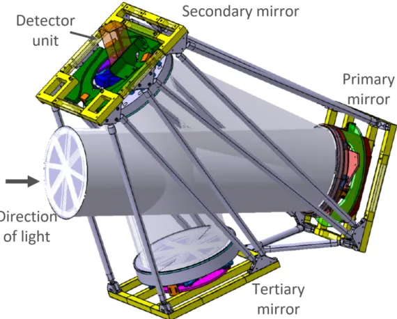
CASTLE is a small sized telescope highly optimized for the detection of extremely faint and extended astro-physical objects. The telescope will be installed at the Calar Alto observatory (in Almeria, Spain). CASTLE has an off-axis fully reflective Schmidt design,9,10composed of an anamorphic primary mirror of 35.6 cm (whose purpose is to replace the entrance correcting Schmidt plate), a flat secondary mirror and a spherical tertiary mirror that focuses the light onto a convex focal surface (Figure 1).
Figure 1. CASTLE mechanical design + mirrors are shown together with the simulated beam of incoming light.
The advantages of such telescope come from its unique design that combines: a) the wide field of view of a Schmidt telescope (2◦.36×1◦.56 with 100per pixel), b) the removal of supporting spiders and related diffraction effects, c) the removal of field flattening optics provided by the usage of a curved sensor to match its curved focal surface. All these elements contribute to generate a Point Spread Function with very low level wings, uniform across the full field of view, and to effectively suppress ghost reflections.9 The detector unit will have a science graded curved CMOS sensor (back-side illuminated to increase the Quantum Efficiency up to 80%). The telescope will be equipped with g, r and wide-band g+r (luminance filter) filters for its science applications and the facility will be robotic.
2.1 Expected performances
Extensive end-to-end photon Monte Carlo simulations were performed to ascertain the performances of the telescope and the results showed that the telescope PSF reaches very low wing levels and also limits ghost reflections.9 They also demonstrated the overall uniformity of the PSF shape across the full field of view where the differences of the PSF at large scales are negligible. The corresponding FWHM under observing seeing conditions of ∼100 resulted to be ∼200.7, which will be properly sampled with CASTLE’s pixel scale of 100.
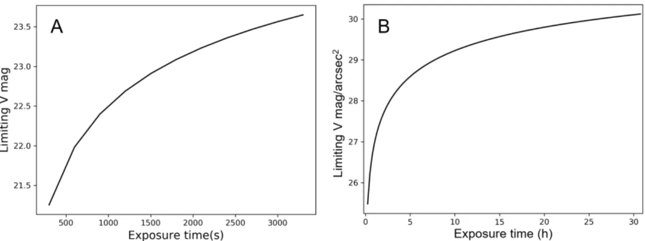
Figure 2. Limiting magnitudes for CASTLE (SNR=5) in V band as function of exposure time. A: limiting magnitudes for point source observations made by stacking frames of 300 s exposure time each. B: limiting surface brightness for extended sources made by stacking frames of 900 s exposure time each.
CASTLE will be used for various science cases (e.g., star like and extended sources) reaching the limiting magnitudes and limiting surface brightness magnitudes listed in Figure2. For these we considered the moonless night-sky surface brightness12 in the V band, V = 22.01 mag arcsec−2.
The point source limiting magnitude is computed by considering exposures integrated over 300 s, and then averaged over the exposure times shown, up to a 1h integration. This provides an example of observing strategy that allows to sample the time variability of the light emitted by the targets, while keeping the exposure time high enough to observe also fainter objects. In the case of the surface brightness, instead, the integration is performed over exposures of 900 s each, keeping the contribution of the sensor readout noise to the global noise budget low (sky dominated signal). For both cases we extract the flux on an aperture of 3σ corresponding to a radius on sky of 600. Given the PSF effective dimension, we expect the limiting surface brightness to be affected in some amount by star crowding. This is usually overcome by using complementary images with better image quality (e.g. from CFHT).
Figure2, together with the results from,9show that CASTLE will be able to reach the typical limiting surface brightness magnitudes needed to observe LSB objects.13–20
In the following Sections we will describe in detail the mechanical design of the telescope (Section 3 and the straylight study done so far (Section 4). We will conclude with the status of the project and the future perspectives (Section5).
3. MECHANICAL DESIGN
The mechanical design is meant to hold the three mirrors in a stress-free fashion. This particular point is extremely important to decrease the degradation of the image quality across the field of view. The full design has a total weight of and it is made in an alloy of aluminium and silicon (Al 6060) that has special properties to reduce the thermal expansion. The structure is made in such a way that several rods connect the three mirror holders and make the structure stiff enough to resist to the gravity load and wind. In Figure1 the mechanical design is shown and one can notice the three mirror holders and the rods connecting them. The space between these rods will be filled with some lightweight cover with a black absorbing coating that will act as overall envelope and light baffle at the same time. A more extended description on the baffling system foreseen for the telescope is in the next section.
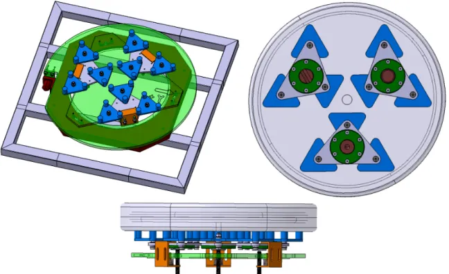
The mirrors are hold in position by a whippletree system which essentially redistribute the mechanical support and decrease the local deflections, contributing in this way to keeping the surface deformation of the optical elements very low.
Figure 3. Top left: top view of the primary mirror cell without mirror, the holding external frame is also shown. Top right: the whippletree system holding the mirror is shown from the back. Bottom: the mirror cell is shown from the side, it is also possible to notice the three screws that determine the mirror position.
In Figure3is shown the 27-points mirror cell for the primary mirror of CASTLE. The secondary and tertiary mirror will also have similar mirror cells. The mirror cell is in fact a standard 6-point cell in which each support pad is replaced by a triangle (in blue) with 3 glued points. Those blue pads are linked to the 3 top level triangles (in grey) with a screw and a stack of concave and convex shims in order to tighten them and at the same time give one degree of freedom to avoid stress accumulation in the glued points when the mirror will be deformed (gravity, thermal expansion). On the other side of the top level triangles, three different contact areas are fixed (one line, one plane and one dot), see Figure3top right. One adjustment screw will be in contact on each brown area ( 3 threads are in the green transparent part, Figure3 bottom) and the assembly is held by the orange interfaces and springs. By using one screw we can modify the tip, 2 will adjust the tilt, and by moving three screws we will adjust the focus. This system will be used during the alignment procedure to fine tune the position of each mirror.
For the primary mirror of CASTLE an additional rotation stage (in red) is placed below the frame. A bigger circular part is fixed on the tip/tilt stage, which is in contact with the red interface by a small but wide cylinder. Two parts are held together with 3 screws at 120° and the adjustment in clocking is made with the accuracy screw on the left side of Figure3 top left. Then the mirror assembly is fixed onto the structure of the telescope with 4 screws at the back of the clocking stage. This is necessary to adjust the orientation of the mirror as it is the only asymmetric mirror in CASTLE.
We can also notice, in Figure1, that behind the secondary mirror we have the filter wheel (in blue), with 5 filter slots available, and the detector box (in orange). Finally, the detector unit will be mounted on a traslation stage allowing us to perform small position adjustment along the optical axis, thus focusing the telescope during the observation runs.
Before finalising the design of the mechanical mount, the entire structure will be object of a finite element analysis, to make sure that the design will perform as expected under temperature changes and wind loads
Table 1. Parameters of straylight analysis
Surface Coating Reflectance at 0◦ incidence
Mirrors Protected Al 92%
Detector Standard AR 2%
Mechanical parts Acktar Fractal black 0.001%
Light sources Brightness Position
Star in the center 11.1 mag [0◦,0◦]
Star in the corner 11.1 mag [0.78◦, 1.18◦]
Star out of field 11.1 mag [1.56◦, 2.36◦]
Full Moon -12.74 mag [0◦, 20◦]
Component modelled Scattering model Assumed parameter
Mirror K-corr. B=38.6 mm, σ=2.08, rms=5 nm
Refractive surfaces K-corr. B=3.37 µm , σ=1.29, rms=15 mum
typically observed at CAHA.
4. STRAYLIGHT ANALYSIS
In this section we turn our focus into the study of the straylight within CASTLE. We put particular attention to this well know issue in optical design, as one of the science topics for CASTLE is the observation of the ultra-low surface brightness universe. A great effort was put into the optimization of the optical design for CASTLE in order to fulfill this goal, thus, a good control over the straylight present in the telescope is an important step to improve our chance to detect such faint and extended objects.
A list of input parameters used in the straylight modeling is in Table1.
Figure 4. Set-up for the straylight analysis of CASTLE. The yellow light source at the top left represents the illumination of the Moon, that mostly hit the walls of the mechanical structure. Also the entrance cylindrical baffle is represented in the image. Three wavelengths were considered for this study: 350 nm, 560 nm, 1000 nm.
The entire mechanical structure is closed in an envelop made with light plates coated with Acktar Fractal black.21,22 It provides a high light absorption with the residual integral scattering varying in the range of 0.002 − 0.17% from the normal to grazing incidence. In addition, a cylindrical baffle is placed at the entrance beam position. The entrance baffle has perpendicular circular vanes of 30 mm depth placed with 10 mm clearance from the beam and the spacing between adjacent vanes is 17 mm. This substructure is aimed at suppressing wide angle incoming light even further. Finally, light baffles have also been placed around the mirrors edge to cover the edge of the mirrors and the mirror cell structure.
For the straylight analysis the scattering on the mirror surface due to micro-roughness is computed starting with the K-correlation model,23 which allows using the surface roughness explicitly. Other parameters of the model describe the surface roughness power distribution spectrum (PSD) via its’ cut-off frequency (B) and slope (σ). The PSD model was calibrated by experimental data from24 and the parameters found for high-quality mirror are B = 38.6mm, σ = 2.08. The same procedure is applied to the description of the refractive surfaces present in CASTLE, the filter and the detector window. This time we used parameter values of the surface PSD were B = 3.37µm, σ = 1.29. For each mirror the total integral scattering results to be 1.09% and for the refractive surfaces 0.043%. These values are computed at a wavelength of 550 nm. The K-correlation model23 includes recalculation of the straylight for other wavelengths, thus allowing to cover the entire CASTLE working range.
Four main sources of light are considered for the straylight analysis : three stars, one in the center, the second one at the corner of the field of view, the third one out of the field at the doubled field angle, and the full Moon placed just outside of the field of view observed (at 20◦) and represented as an ideal collimator + a circular source with 3000angular size. This is the worse possible scenario of a bright source outside the field of view, as the observations will be typically done at larger angular distances from the Moon (>30◦) and when observing ULSB structures the Moon will be even farther away (>60◦) and closer to new Moon phase, in order to decrease as much as possible the brightness of the background and the effects of such wide angle light scattering in the optics.
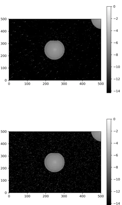
The result of the straylight analysis is shown in Figure 5 where two cases were considered: at the top, the straylight only due to the optical components (the mechanical structure was 100% absorbing.), at the bottom, the straylight due to the entire system, including the mechanical structure. For computational time reasons the two maps have larger pixels than the future CASTLE detector, which will be 4.4×4.4µm. The pixel dimensions in x and y direction in this case are 73.1×48.3µm.
The maps have also been normalized to the maximum illumination in the central pixel of the first simulation (2.08×10⁻⁹ W). Note that the asymmetric shape of the star illumination at the center of the field of view is due to a mismatch between the mechanical design and the telescope light path, and it will be solved in future studies. From a qualitative analysis of the two maps we obtain the following information:
• There is a large ghost caused by the reflections on the filter, detector window and detector surface. This ghost is highly suppressed showing values of 10−5.5 very close to the center and decreasing down to 10−8 within a radius of ∼ 300.
• There is a diffuse scattering across the entire field of view, most likely due to the micro-roughness of the mirrors, at least for the case with optics-only simulation.
• From the simulation with only optical elements we can see in particular that there are few more powerful rays deposited at the opposite corner with respect to the star located at one corner of the field of view. Thus, this might show the presence of a very unfocused ghost of that star.
• The comparison of the two maps shows that the ghosts do not appear different, but there is a significant increase of rays scattered at larger scales. This particular effect might be due to the presence of the Moon illumination. In the case of the only optics simulations the Moon was not generating any effect as the rays were directly illuminating the walls of the telescope, but not any of the optical elements. This also means, that the effect of the micro-roughness of the mirrors on the overall scattering is subdominant with respect to the mechanical structure scattering.
• The third star, placed at double the field of view, does not show any trace in the optics-only simulation and it is just a very minor contributor to the large scale scattering of the full-system simulation.
These results show the importance of performing a straylight analysis during the design phase of a telescope to improve its final performances and limit as much as possible the undesired systematic effects. Unfortunately we can not perform at this stage a more quantitative analysis of these results due to a lack of statistics in the illumination sampling of the different sources. Even though the power deposited by the rays at very large distances from the center with respect to the center itself is of the order of 10−6 for the brightest pixels and 10−9 for the others (which are the majority), we expect these numbers to be even lower and more in line with
the results shown in.9 Two effects are happening at the same time in the simulation: 1) the sampling of the focal surface has pixels whose area is almost 200 times larger than the future CASTLE detector, thus collecting more light, 2) the total power emitted by the light sources is distributed over a finite number of rays, thus making the rays in the ghost halo around the stars and at larger distances from the center, brighter than they would be.
Additional baffling systems and black coatings will be tested in order to mitigate the effects listed above. Particular care will be taken during the testing phase of the detector block. New AR coatings will be applied to the refractive surfaces if deemed necessary from the tests results.
5. STATUS & PERSPECTIVES
We have shown here the CASTLE design and the main expectations in terms of performances. During this and next year the project will undergo an intensive phase of construction, tests and integration. The detector unit is currently under development. The first unit will include a flat version of a front side illuminated sensor, which will be substituted by an identical, but curved sensor in a later stage. The final back side illuminated curved detector planned for CASTLE will be available only during the final integration phase of the telescope.
The secondary and tertiary mirrors of CASTLE have been already manufactured and the primary is going to be completed by the end of the year. One of the planned upgrades envisioned for CASTLE is the replacement of the monolithic primary mirror (currently under manufacturing) with a primary manufactured by using the stress mirror polishing technique (SMP). Active optics methods25 in astronomy provide high imaging quality. CASTLE will benefit of highly deformable active optics methods that can generate non-axisymmetric aspheric surfaces or freeform surfaces26,27by use of a minimum number of actuators. The aspheric mirror, in this case, is obtained from a single uniform load that acts over the whole surface of a closed-form substrate whilst under axial reaction to its elliptical perimeter ring during polishing.28,29 The manufacturing of the primary mirror with the SMP technique will also decrease the large angle scattering of the incoming light, thus limiting its contribution to the PSF wings30and decreasing the effect observed in Section4. The mechanical design of CASTLE (Section3) is made in such a way that it will be easily able to accommodate the new primary mirror, even with larger dimensions and thickness.
Once all the three mirrors (in the configuration with the “classic” primary mirror) and the mirror cells will be ready (spring 2021) The testing phase, adding the different components one by one, will begin . The final integration and commissioning on site at the CAHA observatory is due by the end of next year/beginning of 2022.
ACKNOWLEDGMENTS
The authors acknowledge the support of the European Research council through the H2020 - ERC-STG-2015 – 678777 ICARUS program, the H2020-ERC-PoC-2018 - CURVE-X - 839271, the MERAC foundation and the European Astronomical Society who are funding the project. This activity was partially funded by the French Research Agency (ANR) through the LabEx FOCUS ANR-11-LABX-0013.
REFERENCES
[1] Guenter, B., Joshi, N., Stoakley, R., Keefe, A., Geary, K., Freeman, R., Hundley, J., Patterson, P., Hammon, D., Herrera, G., Sherman, E., Nowak, A., Schubert, R., Brewer, P., Yang, L., Mott, R., and McKnight, G., “Highly curved image sensors: a practical approach for improved optical performance,” Optics Express 25, 13010 (June 2017).
[2] Iwert, O., Ouellette, D., Lesser, M., and Delabre, B., “First results from a novel curving process for large area scientific imagers,” in [High Energy, Optical, and Infrared Detectors for Astronomy V ], Proc. SPIE 8453, 84531W (July 2012).
[3] Dumas, D., Fendler, M., Baier, N., Primot, J., and le Coarer, E., “Curved focal plane detector array for wide field cameras,” Applied Optics 51, 5419 (Aug. 2012).
[4] Tekaya, K., Fendler, M., Inal, K., Massoni, E., and Ribot, H., “Mechanical behavior of flexible silicon devices curved in spherical configurations,” in [14th International Conference on Thermal, Mechanical and Multi-Physics Simulation and Experiments in Microelectronics and Microsystems ], 7 pages – Article number 6529978, IEEE - Institute of Electrical and Electronics Engineers, Wroclaw, Poland (Apr. 2013).
[5] Itonaga, K., Arimura, T., Matsumoto, K., Kondo, G., Terahata, K., Makimoto, S., Baba, M., Honda, Y., Bori, S., Kai, T., Kasahara, K., Nagano, M., Kimura, M., Kinoshita, Y., Kishida, E., Baba, T., Baba, S., Nomura, Y., Tanabe, N., Kimizuka, N., Matoba, Y., Takachi, T., Takagi, E., Haruta, T., Ikebe, N., Matsuda, K., Niimi, T., Ezaki, T., and Hirayama, T., “A novel curved cmos image sensor integrated with imaging system,” in [2014 Symposium on VLSI Technology (VLSI-Technology): Digest of Technical Papers ], 1–2 (June 2014).
[6] Gregory, J. A., Smith, A. M., Pearce, E. C., Lambour, R. L., Shah, R. Y., Clark, H. R., Warner, K., Osgood, R. M., Woods, D. F., DeCew, A. E., Forman, S. E., Mendenhall, L., DeFranzo, C. M., Dolat, V. S., and Loomis, A. H., “Development and application of spherically curved charge-coupled device imagers,” Applied Optics 54, 3072 (Apr. 2015).
[7] Lombardo, S., Behaghel, T., Chambion, B., Caplet, S., Jahn, W., Hugot, E., Muslimov, E., Roulet, M., Ferrari, M., Gaschet, C., and Henry, D., “Curved detectors for astronomical applications: characterization results on different samples,” Appl. Opt. 58, 2174–2182 (Mar 2019).
[8] Richard, J., Bacon, R., et al., “BlueMUSE: Project Overview and Science Cases,” arXiv e-prints , arXiv:1906.01657 (June 2019).
[9] Lombardo, S., Muslimov, E., Lemaˆıtre, G., and Hugot, E., “Next-generation telescopes with curved focal surface for ultralow surface brightness surveys,” MNRAS 488, 5057–5064 (Oct 2019).
[10] Muslimov, E., Valls-Gabaud, D., Lemaˆıtre, G., Hugot, E., Jahn, W., Lombardo, S., Wang, X., Vola, P., and Ferrari, M., “Fast, wide-field and distortion-free telescope with curved detectors for surveys at ultralow surface brightness,” Appl. Opt. 56, 8639 (Oct. 2017).
[11] Lombardo, S., Prada, F., Hugot, E., Basa, S., Bautista, J. M., Boissier, S., Boselli, A., Bosma, A., Cuillandre, J. C., Duc, P. A., Ferrari, M., Grosso, N., Izzo, L., Joaquina, K., Junais, Koda, J., Lamberts, A., Lemaitre, G. R., Longobardi, A., Mart´ınez-Delgado, D., Muslimov, E., Ortiz, J. L., Perez, E., Porquet, D., Sicardy, B., and Vola, P., “CASTLE: performances and science cases,” arXiv e-prints , arXiv:2006.13956 (June 2020). [12] Barrado, D., Thiele, U., Aceituno, J., Pedraz, S., S´anchez, S. F., Aguirre, A., Alises, M., Bergond, G.,
Galad´ı, D., Guijarro, A., Hoyo, F., Mast, D., Montoya, L., Sengupta, C., de Guindos, E., and Solano, E., “The Calar Alto Observatory: current status and future instrumentation,” in [Highlights of Spanish Astrophysics VI ], Zapatero Osorio, M. R., Gorgas, J., Ma´ız Apell´aniz, J., Pardo, J. R., and Gil de Paz, A., eds., 637–646 (Nov. 2011).
[13] Mart´ınez-Delgado, D., “The Stellar Tidal Stream Survey,” in [Highlights on Spanish Astrophysics X ], Mon-tesinos, B., Asensio Ramos, A., Buitrago, F., Sch¨odel, R., Villaver, E., P´erez-Hoyos, S., and Ord´o˜ nez-Etxeberria, I., eds., 146–154 (Mar. 2019).
[14] van Dokkum, P. G., Abraham, R., Merritt, A., Zhang, J., Geha, M., and Conroy, C., “Forty-seven Milky Way-sized, Extremely Diffuse Galaxies in the Coma Cluster,” ApJL 798, L45 (Jan. 2015).
[15] Knapen, J. H. and Trujillo, I., “Ultra-Deep Imaging: Structure of Disks and Haloes,” in [Outskirts of Galaxies ], Knapen, J. H., Lee, J. C., and Gil de Paz, A., eds., Astrophysics and Space Science Library 434, 255 (2017).
[16] Mihos, J. C., Harding, P., Feldmeier, J. J., Rudick, C., Janowiecki, S., Morrison, H., Slater, C., and Watkins, A., “The Burrell Schmidt Deep Virgo Survey: Tidal Debris, Galaxy Halos, and Diffuse Intracluster Light in the Virgo Cluster,” ApJ 834, 16 (Jan. 2017).
[17] Abraham, R. G. and van Dokkum, P. G., “Ultra-Low Surface Brightness Imaging with the Dragonfly Telephoto Array,” PASP 126, 55 (Jan. 2014).
[18] Duc, P.-A., Cuillandre, J.-C., Karabal, E., Cappellari, M., Alatalo, K., Blitz, L., Bournaud, F., Bureau, M., Crocker, A. F., and Davies, R. L., “The ATLAS3D project - XXIX. The new look of early-type galaxies and
surrounding fields disclosed by extremely deep optical images,” MNRAS 446, 120–143 (Jan 2015).
[19] Boissier, S., Gil de Paz, A., Boselli, A., Buat, V., Madore, B., Chemin, L., Balkowski, C., Amram, P., Carignan, C., and van Driel, W., “GALEX Observations of Low Surface Brightness Galaxies: UV Color and Star Formation Efficiency,” ApJ 681, 244–257 (Jul 2008).
[20] Rom´an, J. and Trujillo, I., “Ultra-diffuse galaxies outside clusters: clues to their formation and evolution,” MNRAS 468, 4039–4047 (July 2017).
[21] Adibekyan, A., Kononogova, E., Monte, C., and Hollandt, J., “High-Accuracy Emissivity Data on the Coatings Nextel 811-21, Herberts 1534, Aeroglaze Z306 and Acktar Fractal Black,” International Journal of Thermophysics 38, 89 (July 2017).
[22] Schr¨oder, S., Trost, M., Herffurth, T., von Finck, A., and Duparr´e, A., “Light scattering of interference coatings from the IR to the EUV spectral regions,” Advanced Optical Technologies 3, 113–120 (Feb. 2014). [23] Dittman, M. G., “K-correlation power spectral density and surface scatter model,” in [Society of Photo-Optical Instrumentation Engineers (SPIE) Conference Series ], Uy, O. M., Straka, S. A., Fleming, J. C., and Dittman, M. G., eds., Society of Photo-Optical Instrumentation Engineers (SPIE) Conference Series 6291, 62910R (Aug. 2006).
[24] Wang, Y. and Wolfe, W. L., “Scattering from microrough surfaces: comparison of theory and experiment,” J. Opt. Soc. Am. 73, 1596–1602 (Nov 1983).
[25] Lemaitre, G. R., [Astronomical Optics and Elasticity Theory – Active Optics Methods ], Springer-Verlag Berlin Heidelberg (2009).
[26] Forbes, G. W., “Characterizing the shape of freeform optics,” Opt. Express 20, 2483–2499 (Jan 2012). [27] Hugot, E., Agocs, T., Challita, Z., Jasko, A., Kroes, G., Banyai, E., Miller, C., Taylor, W., Schnetler, H.,
and Venema, L., “FAME: Freeform Active Mirrors Experiment,” in [Proc. SPIE ], Society of Photo-Optical Instrumentation Engineers (SPIE) Conference Series 9151, 915107 (July 2014).
[28] Lemaitre, G. R., “Active optics with a minimum number of actuators,” Advanced Optical Technologies 3(3), 223 – 249 (2014).
[29] Hugot, E., Lemaˆıtre, G. R., and Ferrari, M., “Active optics: single actuator principle and angular thickness distribution for astigmatism compensation by elasticity,” Appl. Opt. 47, 1401–1409 (Apr 2008).
[30] Lemaitre, G., Vola, P., and Muslimov, E., “Active optics in astronomy: Freeform mirror for the messier telescope proposal,” Mathematical and Computational Applications 24, 2 (Dec 2018).
Figure 5. Light distribution at the focal surface of the telescope due to the illumination of the sources listed in Table1. The images are normalized with respect to the brightest pixel of the image at the top (the central pixel) and they are plotted in logarithmic units. Top: simulation performed considering only the optical elements of the system and perfectly absorbing mechanical structure. Bottom: simulation performed on the entire system, including realistic scattering from the mechanical structure.