Publisher’s version / Version de l'éditeur:
Vous avez des questions? Nous pouvons vous aider. Pour communiquer directement avec un auteur, consultez la première page de la revue dans laquelle son article a été publié afin de trouver ses coordonnées. Si vous n’arrivez pas à les repérer, communiquez avec nous à [email protected].
Questions? Contact the NRC Publications Archive team at
[email protected]. If you wish to email the authors directly, please see the first page of the publication for their contact information.
https://publications-cnrc.canada.ca/fra/droits
L’accès à ce site Web et l’utilisation de son contenu sont assujettis aux conditions présentées dans le site
LISEZ CES CONDITIONS ATTENTIVEMENT AVANT D’UTILISER CE SITE WEB.
Canadian Building Digest, 1964-09
READ THESE TERMS AND CONDITIONS CAREFULLY BEFORE USING THIS WEBSITE. https://nrc-publications.canada.ca/eng/copyright
NRC Publications Archive Record / Notice des Archives des publications du CNRC :
https://nrc-publications.canada.ca/eng/view/object/?id=897fca5e-67e2-46e0-9e83-c2c456faadf1
https://publications-cnrc.canada.ca/fra/voir/objet/?id=897fca5e-67e2-46e0-9e83-c2c456faadf1
NRC Publications Archive
Archives des publications du CNRC
For the publisher’s version, please access the DOI link below./ Pour consulter la version de l’éditeur, utilisez le lien DOI ci-dessous.
https://doi.org/10.4224/40000868
Access and use of this website and the material on it are subject to the Terms and Conditions set forth at
Vapour diffusion and condensation
Canadian Building Digest
Division of Building Research, National Research Council Canada
CBD 57
Vapour Diffusion and Condensation
Originally published September 1964 J.K. Latta and R.K. Beach
Please note
This publication is a part of a discontinued series and is archived here as an historical reference. Readers should consult design and regulatory experts for guidance on the applicability of the information to current construction practice.
Water in various forms is a principal agent in building deterioration and its control is a prime responsibility of the designer. Vapour diffusion is one mechanism whereby water can find its way into the components of a building and damage the materials or assemblies, although it is not the only one. In many instances it may be of less importance than others such as rain penetration or air leakage which transports water vapour with it. Vapour diffusion must, however, always be considered. This Digest describes a method whereby the designer can choose and position his materials so that harmful accumulation of water resulting from diffusion can be prevented. In spite of its limitations, this method provides a basis for judgement on many aspects of condensation control.
Characteristics of Air-Vapour Mixtures
Water vapour is one of the several gaseous constituents of air, the other principal ones being nitrogen, oxygen and carbon dioxide. Each exerts its own partial pressure in proportion to the amount of gas present, the sum of the pressures making up the total or barometric pressure of the air. When there is a difference in concentration of one of these gases between two points, there will be a corresponding difference in partial pressure. This will cause a flow of that particular gas from the point of higher concentration to the lower. When a partial pressure difference exists between two sides of a material, the gas involved will diffuse through the material until the partial pressures of that gas are equalized. The rate of diffusion will be determined by the partial pressure difference, the length of the flow path, and the permeability to the particular gas involved of the medium through which flow is taking place.
In the normal range of atmospheric temperatures and pressures, water can exist in three different states: gas, liquid and solid. The maximum amount of water that can exist in the gaseous state (vapour) is limited by the temperature. Thus, if any air-vapour mixture is cooled, a temperature will be reached at which it will be saturated, and if cooling is continued below this point water will condense. If the temperature at which the air becomes saturated, i.e. the dew-point, is above the freezing dew-point, the vapour will condense to a liquid, if it is below freezing, it will condense as ice in the form of hoar frost.
The ratio between the weight of water vapour actually present in the air and the weight it can contain when saturated at the same temperature is called the relative humidity of the air. It is
usually expressed as a percentage. As the vapour pressures are set by the quantities of vapour in the air, the relative humidity is also given by the ratio between the actual vapour pressure and the saturation vapour pressure at the same temperature. Thus, if the temperature and relative humidity are known the actual vapour pressure can be calculated from the product of the relative humidity (expressed as a decimal) and the saturation pressure. These saturation vapour pressures and the corresponding quantities of water in the air are given in psychrometric tables such as those in theGuide and Data Book of the American Society of Heating, Refrigerating and Air-Conditioning Engineers.
Calculation of Vapour Flow
Once the vapour pressures on the two sides of the building envelope are known and a selection and arrangement of the building materials has been made, the vapour flow calculation is carried out in a manner similar to that used for heat flowCBD 36). The relation that
Vapour Flow =
Vapour Pressure Difference
Vapour Flow Resistance
is similar to that for heat flow. There is, however, one important difference owing to the ability of the vapour to condense. The initial calculation is based on the premise that there is a continuity of flow and that all the vapour entering the envelope on the high vapour pressure side will emerge on the low vapour pressure side. If, on its passage through the building envelope, the vapour is cooled to below the dew-point, condensation will occur and the basis of the calculation is upset. Even so once the plane of condensation has been established the method can be applied to calculate the flow of vapour to it and away from it. The difference between the two gives the accumulation of water within the envelope.
The vapour flow resistance of a material is the inverse of the ability of the material to permit vapour to flow, i.e. its permeance. The unit of permeance is called the "perm," which is defined as one grain of water passing through one square foot in one hour under the action of a vapour pressure differential of one inch of mercury. The corresponding unit of permeability is the "perm-inch," the permeance of unit thickness. Values of the permeance of various building materials, together with further discussion of flow calculations and moisture problems, are to be found in the chapter entitled "Moisture in Building Construction" of the ASHRAE Guide and Data
Book, Fundamentals and Equipment. Unfortunately, the information available provides only
partial coverage of even common materials. One reason for this is that the simple flow approach inadequately describes the real situation in many materials, and unlike heat flow, it is often impossible to describe the flow properties of a material in terms of a single coefficient applicable over a wide range of conditions. It is proposed to deal with this aspect of moisture migration in materials in a separate Digest.
The present information, however, does provide a basis for the design of building envelopes that eliminate many of the problems associated with moisture migration. The following example illustrates the process of calculating the vapour pressure gradient and the manner in which it may be used to avoid condensation problems.
Table I. Tabulated Vapour and Temperature Calculations
Air Film Plaste r Insulatio n Concret e Air Film Total
Thickness n - ¾ 1 4 Permeance M - 15 - - -Permeabilit y µ - - 1.6 3.2 -Vapour Resistance 1/M , n/µ 0 0.07 0.62 1.25 0 1.94 Vapour Pressure Drop for Continuity 0 0.009 0.082 0.165 0 0.256 Vapour Pressure for Continuity pc 0.286 0.286 0.277 0.195 0.03 0 0.030 Thermal Conductanc e C 1.46 6.66 - - 6.00 Thermal Conductivit y k - - 0.25 12.0 -Thermal Resistance 1/C , n/k 0.68 0.15 4.00 0.33 0.17 5.33 Temperatur e Drop 9 2 55 5 2 73 Temperatur e 73 64 62 7 2 0 Saturation Vapour 0.818 0.601 0.560 0.054 0.042 0.038
Pressure ps
Actual Vapour Pressure pa
0.286 0.286 0.264 0.054 0.030 0.030
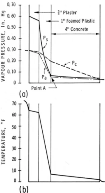
Example. Consider a wall of 4-inch reinforced concrete with an inside finish of winch plaster over
1 inch of foamed plastic insulation that separates an internal environment of 73°F and 35 per cent RH from an outside environment of 0°F and 80 per cent RH. The actual vapour pressures are, respectively, 0.818 x 0.35 = 0.286 in. Hg and 0.038 x 0.80 = 0.030 in. Hg, and the total pressure difference is 0.256 in. Hg. This pressure difference must be apportioned among the various components of the envelope in proportion to their resistance to vapour flow. These calculations are tabulated in Table I and the resulting vapour pressure gradient for continuity of flow is plotted in Figure 1 as curve pc. Up to this point the method is the same as that for the arithmetical determination of temperature gradient. No value for the permeability of foamed plastic insulation is given in the 1963 edition of the ASHRAE Guide, but depending on the type it varies between 0.75 and 5.0 perm-in.
To discover whether condensation will take place the temperature gradient must be determined so that the corresponding saturation vapour pressure curve can be obtained. This is tabulated in Table I and the saturation vapour pressure curve plotted in Figure 1 as curve ps. The values for the temperature gradient have been rounded off to the nearest degree (CBD 36). Although no greater accuracy than two decimal places is warranted in the vapour flow calculations, the third decimal place has been retained in the example for clarity. Note that a uniform drop in temperature through a material gives a curved saturation vapour pressure line. It may be seen that the pscurve is above the pccurve on the warm side of the wall, crosses to below it in the foamed plastic, and finally rises above the pccurve near the cold face of the concrete. As the maximum amount of water that can exist as vapour is set by the temperature, which also establishes the saturation vapour pressure, the actual vapour pressure curve can never be above the saturation vapour pressure curve. Thus, when the pccurve lies above the pscurve condensation will take place and a discontinuity of flow will exist.
Figure 1. Vapour pressure and temperature gradients of original wall
Under equilibrium conditions condensation does not take place at the point where the two curves cross; it can usually be assumed to occur at the next interface. The actual vapour pressure gradient between the inside and point A and between point A and the outside can now be determined by calculation, using the saturation vapour pressure of O.O53 in. Hg at point A. This calculation is tabulated in Table I and plotted in Figure 1 as curve pa.
The vapour flow to point A is 0.286 - 0.054
0.07 + 0.62
and that from point A 0.054 - 0.030
1.25
=0.02 grain/sq ft/hr
giving a condensation rate of 0.34 - 0.02 = 0.32 grain/sq ft/hr.
Methods of Preventing Condensation
To avoid condensation the designer must arrange that the saturation vapour pressure curve always lies above the vapour pressure curve for continuity of flow. In broad terms this can be achieved by adjusting the vapour flow resistances, which will change the pccurve; by adjusting the thermal resistances which will change the pscurve; or by a combination of the two.
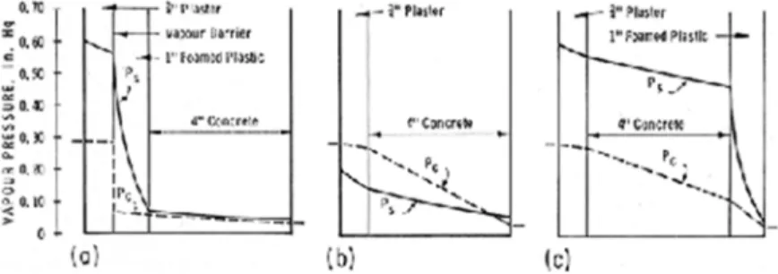
The initial reaction is to change the vapour flow resistances by adding a vapour barrier on the warm side. The total resistance required to prevent condensation can be calculated by dividing the vapour pressure drop from the warm side to point A by the rate of flow from point A to the outside, giving 11.6 units of resistance. The plaster and the insulation provide 0.69 unit of resistance, leaving 10.9 units to be provided by the vapour barrier. Thus, the vapour barrier should not have a permeance greater than 1/10.9 = 0.09 perm. Adding such a vapour barrier between the plaster and the insulation will produce the vapour pressure curve shown in Figure 2a. It will not materially alter the temperature gradient or the pscurve.
Figure 2. Vapour pressure gradients of modified wall
The installation of such a vapour barrier, which would have to be of 4-mil polyethylene or better, raises various practical problems. This leads one to consider the alternative method of changing the pccurve: reduction of the vapour flow resistance between point A and the outside. The maximum resistance tolerable is given by the quotient of the pressure drop to the outside and the rate of flow from the inside to point A, i.e. 0.024/0.34 = 0.071 unit of resistance, giving a required permeance of at least 14 perms. This can only be achieved by replacing the concrete with a structural member of the required permeability.
The second general method of attacking the problem is to raise the pscurve by raising the temperature on the warm side of the concrete. Removing insulation from the warm side of the wall will have this effect, but with this particular design condensation will still take place (Figure 2b). In any case, the reduction in insulation will increase the heat loss through the wall and reduce the inside surface temperature, neither of which may be acceptable.
Alternatively, additional insulation can be added on the outside, but the same effect can be achieved simply by reversing the relative positions of the concrete and the insulation. This results in a most satisfactory wall design (Figure 2c), but requires an exterior weathering
surface to protect the insulation. Such a surface should either have a high permeance or be designed as an open rain screen.
Although for the sake of clarity the effects of adjusting the vapour resistance and the thermal resistance of the wall have been discussed separately, in practice it is usual to adjust both to obtain the most satisfactory over-all solution.
These examples show that although a component of the wall may be selected initially to fulfil a primary function such as structural strength or thermal resistance, it may also have an effect on the vapour and thermal properties of the wall. In particular, the vapour resistance of the insulation can have a significant effect on the proper location of the insulation in the wall.
Tolerance to Condensation
Thus far the discussion has dealt with methods of avoiding any condensation. In many cases, however, some condensation can be tolerated, the amount depending on the waterholding capacity or water tolerance of a particular construction under particular conditions of use. If some condensation is to be permitted, then the materials must have adequate opportunity to dry. The effect of frost action on wet materials, the sudden release of accumulations of ice, dimensional changes produced by changes in moisture content, and many other factors must be considered before this solution is adopted.
These vapour flow calculations can be considered reasonably accurate when the primary mechanism for moisture migration is vapour diffusion and when coefficients are available that define the rate of vapour flow for the material under the conditions of use. When, however, the material is capable of holding substantial quantities of absorbed water, the diffusion approach may be inadequate or even inappropriate, depending on the situation. Nevertheless, these calculations provide the best available basis for improved judgement on condensation control.