Publisher’s version / Version de l'éditeur:
ASTM Bulletin, 214, pp. 37-44, 1956-07-01
READ THESE TERMS AND CONDITIONS CAREFULLY BEFORE USING THIS WEBSITE. https://nrc-publications.canada.ca/eng/copyright
Vous avez des questions? Nous pouvons vous aider. Pour communiquer directement avec un auteur, consultez la première page de la revue dans laquelle son article a été publié afin de trouver ses coordonnées. Si vous n’arrivez pas à les repérer, communiquez avec nous à [email protected].
Questions? Contact the NRC Publications Archive team at
[email protected]. If you wish to email the authors directly, please see the first page of the publication for their contact information.
NRC Publications Archive
Archives des publications du CNRC
This publication could be one of several versions: author’s original, accepted manuscript or the publisher’s version. / La version de cette publication peut être l’une des suivantes : la version prépublication de l’auteur, la version acceptée du manuscrit ou la version de l’éditeur.
Access and use of this website and the material on it are subject to the Terms and Conditions set forth at
Philosophy on loading tests
Dorey, D. B.; Schriever, W. R.
https://publications-cnrc.canada.ca/fra/droits
L’accès à ce site Web et l’utilisation de son contenu sont assujettis aux conditions présentées dans le site LISEZ CES CONDITIONS ATTENTIVEMENT AVANT D’UTILISER CE SITE WEB.
NRC Publications Record / Notice d'Archives des publications de CNRC:
https://nrc-publications.canada.ca/eng/view/object/?id=64a84a93-c959-49cd-9482-71d907eed034
https://publications-cnrc.canada.ca/fra/voir/objet/?id=64a84a93-c959-49cd-9482-71d907eed034
Sar
TH].
N2l-t2
no. 39
e-. 2
BI,DG ]
N A T I O N A T
D t v t S l o N
o F
R E S E A R C H
C A N A D A
B U I T D I N G
c o u N c l t
R E S E A R C H
DBRINRC
Publications
Copy
A PHILOSOPHY
ON LOADING TESTS
by
D. B. DOREY
AND W. R. SCHRIEVER
A N A t . Y Z E D
Authorized Reprint from the Copyrighred' . ASTM Bulletin No. 214
M o y 1 9 5 6
THE AMERICAN SOCIETY FOR TESTING MATERIALS Philodelphio 3' Po.
TECHNICAL
PAPER
NO. 39
OF THE
DIVISION
OF BUILDING
RESEARCH
Tr HIS publication is being disributed by the Division of
T-^
Building Research of the National Research Council as a
contribution towards better building in Canada. It should
not be reproduced in whole or in part, without permission of
the original publisher. The Dfvision would be glad to be of
assistance in obtaining such permission.
Publications of the Division of Building Research may be
obtained by mailing the appropriate remittance, (a Bank,
Ex-press, or Post Office Money Order or a cheque made payable
at pvr in Ottawa, to the Receiver General of Canada, credit
National Research Council) to the National Research Council,
Ottawa. Stamps are not acceptable
A coupon system has been introduced to make payments
for publications relatively simple. Coupons are available in
denominations of 5,25, and 5o cenrs, and may be obtained by
making a remittance as indicated above. These coupons may
be used for the purchase of all National Research Council
publications including specifications of the Canadian
Govern-ment Specifications Board,.
A Philosophy
on Loading Tests.
Bv D. B. Dorey and \(/. R. Schriever
A review of Building Codes indi-cates a lack of uniformity in loading test specifications. A new approach to the hrmulation of test loadings and criteria is desirable in the light of technological advance
as a criterion for acceptance. Only two of the specifications listed state a minimum age for the concretie before the test is started.
Many clauses differentiate between a "strength test" and a "performance test" (see third column of Table I) although the use of these terms is not always the same. In the tests re-ferred to as "strength tests," all the criteria (no signs of failure, deflection, and recovery) have been used by one code or another. Generally, the term "performance test" is applied to a check on deflection, under a load varying from 1 X live load to 1* X live load * 4 X dead load. Some codes refer to a "workmanship test," under a load of 2 X live load, with requirementS in terms of no signs of failure coupled with a maximum deflection and a minimum recovery in case the deflection (as cal-culated from accepted engineering for-mulas) is exceeded. The British Stand-ard Code of Practice is the only code making a clear distinction between a / \ r,oeoruc test
pro-vides a means of assessing the struc-tural performance of a building or one of its components. A loading test is de-sirable, for instance, when thbre is doubt about the structural adequacy of a construction or when a structure cannot readily or accurately be sub-jected to engineering analysis. In con-ducting and evaluating a loading test many questions arise: What should the magnitude of the test load be? Is it adequate to state the test load simply as a multiple of the design live load? lVhat criteria should be used to judge the success or failure of the structure in passing the test? Should it be a cer-tain maximum deflection, a minimum recovery of deflection after loading, or both, or should it be merely the ability of the structure to sustain the test load for a certain time without showing signs of damage? What should the duration of the test load application be? What other details of the loading procedure should be specified?
Most building codes contain specifi-cations on loading tests and describe to varying degrees the test procedure, but there exists a lack of agreement in the test requirements.
The inadequacy of existing loading test specifications has caused increasing concern in the field of civil and struc-tural engineering, both in practice and in research work. The authors believe that these specifications are not in keeping with the present state of knowl-edge.
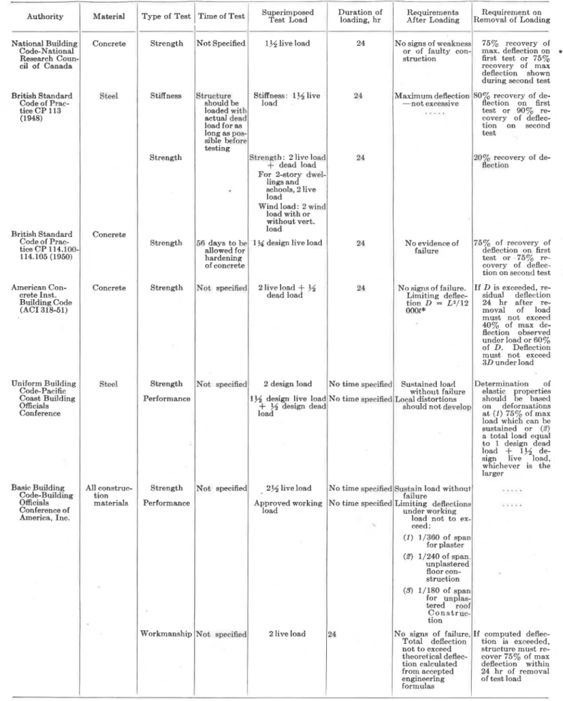
A number of existing loading test specifications found in use in various parts of the world were reviewed by the authors. The chief requirements of these have been summarized in Table I. Review of Building Code Loading
Test Specifications
An examination of Table I will show that these specifications differ in prin-ciple, detail, and procedure. Some specifications for instance deal with con-crete structures only, and use merely the recovery of deflection after the test * Presented at an open meeting of ASTM Committee E-6 on Methods of Testine Building Conqtruetions held ,lune 29, 1955, during the 58th Annual Meeting in Atlantic C i t y , N . , L
NOTE,-DISCUSSION OF THIS PAPER IS INYITED, either for publication or for the attention of the author. Acldress all com-munications to ASTM Headquarters, 1916 Race St., Philadelphia 3, Pa.
May 1956
stiffness and strength test, using de-flection and rccovery as criteria in the first case, and recovery in the second. It should also be noted that not all tests apply to all materials.
From their review of loading test specifications, the authors conclude that a fundamental and thorough re-view of all the factors entering into loading tests on structures is neces-sary before any signi-flcant improve-ment in the specifications can be achieved.
Purpose and Scope of Loading Tests There are many factors to consider in the formulation of a loading test specification. It is, therefore, useful and necessary at this point to outline the types of tests, their purpose and scope, and their relation to design principles.
There are three types of loading tests to consider in the formulation of load-ing test specifications: t'he a,cceptance test, the rating test, and the research test. Each test has its own purpose and specific requirements and all three types bear a close relationship to each other.
"Ihe acceptance test is designed pri-marily to prove the structural ade-quacy of a completed structure or part thereof. Such a test may be required by the building official or owner when
DONALD B. DOREy has been with the Division of Building Research of the National Research Council of Conada for four years, during which time he has been engaged in planning, conducting, and analyzing results of loading tesb.
\(/lLLlAM R. SCHRIEVER has been associated with the Division of Building Research ol the National Rcsearch Council of Canada for eight years and lately engaged in studies of the perform-ance of structures and building design,
. (TPes) 37
A S T M B U L L E T I N
Authority Material Type of Test Concrete Strength National Building Code-National Research Coun. cil of Canada British Standard Code of Prac-tice CP 113 (1948) British Standard Code of Prac-tice CP l14. r14.105 (1950) American Con-crete Inst. Building Code (ACI 3r8-51) Uniform Buildine Code-Paeific -Coast Buildine Officials Conference Stiffness Strength Concrete Strength Concrete Strength Basic Building Code-Buildine Ofrcials Conference of America. Inc. AII construe-tion materials Strength Performanee Strength Performance Workmanship
38
GP96)
A S T M B U L L E T I N
May 1956
TABLE I.-BUILDING CODE-LOADING TEST SPECIFICATIONS,
Time of Test SuperimposedTest Load Duration ofloading, hr RequirementsAfter Loading Removal of LoadingRequirement on
Not Specified llliveload
Stifrness: load llllive should be loaded actual load for as long as sible br testing b : 2 l i v c l o dead load For 2-story Iings and schools, 2 live load Windload: 2 load with or without vert. Ioad
days to l)1 design live load allowed for hardening of concrete spec 2liveload * 14 dead load 24 No signs of 75/6 recovery of max. deflection on first test or 75/s recovery of max deflection shorn during second test 80/e recovery of de-flection on fi.rst test or 9O/6 re-covery of deflec-tion on second test recovery of de-5/6 of recovery oI deflection on first test or 75Vo re-covery of deflec-tion on second test If D is exceeded, re-sidual deflection 24 hr after re-moval of load must not exceed AO/e ol max de-flection observed under load or 60/e ol D. Deflection must not exceed 3D under load Determination of elastic properties should be based on deformatibns at (1) 75/q ot max load which can tre sustained or (9) a total load equal to 1 design dead load * ll de-sign live load, whichever is the larger
lf conputed deflec-tion is exceeded, structure must re-cover 75/s oI max deflection within 24 hr oI removal of test load specified 2 design Ioad Il4 desisn live load
* 14 desig:rr dead load , 2 l l i v e l o a d Approved working Ioad No time No time No time No time specified or of faulty con-struction Maximum deflection -not excessive No evidence of failure No signs of fa.ilure. Limiting deflec-tio? D = L2/12 000r* Sustained load without failure distortions should not in load without failure Limiting under working load not to ex c e e d : ( 1 ) (2) l/360 of span for plaster l/240 of span. unplastered floor con-struction 2live load (e) 1/180 of for tered C o n s t r tion No signs of failure Total deflection not to exceed theoretical deflec-tion calculated from accepted engineering formulas
* Where D : the maximum deflection of the portion of the structure under test, tr : the span of the member under test between faces of sup-ports, and 6 : the depth of the member under test.
TABLE I-(Cont'd) Authority Material Southern Standard Building Code-Southern Building Code Congress Concrete Prefabricated construction (panels)
National Buildi All materials Code-National Board of Fire Underwriters Chicago Building Code and Index-City of Chicago State Building Construction Code-State of New York New Zealand Standard Code of Building By-Laws-New Zealand Standards Inst. Uniform Building Regulations-Melbourne, Australia All materials All materials Concrete and Steel AII materials Concrete Model Building Regulations of South Africa Type of Test Strength Strength Perforrnance Strength Workmanship Strength Performance Performance Strength Strength Strength
May 1956
A S T M B U L L E T I N
(TPe7)
39
Time of SuperimposedTest Load Durtltion ofloading, hr Roquirementsafter loading Removal of LoadingRequirement on If D is exceeded,
structute must re-cover 75/e of ob-served defleetion within 24 hr of removal of test Ioad
75Vo recovery ol ol> served deflection within 24 hr after, removal of full test load
5/e recovery of max deflection within 24 hr of removal of test load
If calculated deflee-tion is exceeded, structure must re-covet lb"/o ol oD-served deflection within 24 hr of re-moval of test load
Not specified lrlliveload | )l dead load
Not specified 2l/2liveload,
1 live load
Not less than 2 sign live load Not specified
Not specified 2 design live load
No signs of failure. Limiting deflec-tion, D = 0.0012'? l2t* load withou failure Measured shall not be than l/360 of clear span o time speci No signs of failure. Total deflection not to exceed that c-alculated by theoretical engi-neering formulas
load failure
No time Limiting deflections (.1) 1/S6Oofspan for plaster (2) r/24O oI unplastered ( 3 ) 1/180 of for tered roof consiruc-tion No time n load structural damage
No time specified No signs of failure
24
Not specified Not specified
2 uniformly distrib-uted imposed load I uniformly
distrib-uted imposed load
Not specified Ample time to be al-lowed for hardening o f before test Not specified 1)l uniformly dis-tributed irnposed load
1507o of load for which structure has been desi
rllliveload | fu
dead load
Limiting deflection at the end of 2
For floor assemblies, residual deflection after first test shall nol exceed 25Vo max deflection under load. Resid-ual deflection on second test not to exceed l.l resid-ual deflection from first test
If D is exceeded, structure must re-cover at'least75/s of observed de-flection within 24 hr after removal of test load Residual deflection not to exceed )d max deflection atr the end of 24-hr period. If there are no algRs o! failure'arid allow-able deflection was exceeded on first test, second test may he qs"-ried out allr/. 72 hr have elogqgd hour period, D : O.OOlL2/r No evidence of f ure. 28 days concrete is placed or on date agreed upon orbeam: llf
design live load *
l$ deadload. Limiting deflection
at the end of 2 h r p e r i o d , ' D : Lz/t2OOOt+ D . B . R . D w g ' *
the structure is incapable of accepted analytical design or when a change in occupancy is requested for an older structure. The purpose of the ac-ceptance test, therefore, is to prove the present quality of the structure and to give a reasonable assurance of safety for the future under normal use.
The rating lest is designed, primarily, to assist the building official in assign-ing an allorvable load to a particular type of construction, especially new types of construction that are mass produced. The rating test must, there-fore, allow for the variability of the specimens in view of the fact that only a certain percentage of all the speci-mens aie tested.
The research Jesd is a scientific in-vestigation of the performance of a structure under loading up to and in-cluding collapse to correlate actual stresses and displacements with those obtained by calculation or other meth-ods in the design.
An important difference between the acceptance test and the rating test and the research test is that in the former, one is not normally concerned with the economy of the design. The acceptance test serves only to establish that a minimum of strength and stiffness is provided, whereas the rating test (when carried to failure) and the re-search test, by exposing the load factor of safety through failure, may ildicate overdesign and thus provide the de-signer with a direct tool for economic design.
Two aspects of the performance should be distinguished, strength (or safety against failure) and stiffness (or arsence of objectionable deflections under rvorking loads). In some cases a structure designed for a required strength will automatically exhibit a satisfactory stiffness; in other cases it will not.
It is essential that a balance be keot between the requirements for design and those for loading tests, otherrvise a properly designed structure may either not pass the Ioading test or the loading test may sanction an under-designed structure. The choice of magnitude of the various test loadings is, therefore, very important. Any improvement or refinement in loading test specifications must keep pace with the status of design speciflcations. However, a loadiug test specification must be kept simple enough to be used and administeled without undue dif-ficul'ty.
Factors to Be Considered in Formu-lating Loading' Test Specifcations The factors to be considered in forrnulating test loadings for structures
a,re many, and they depend upon the type of construction and the intended use of the structure. If, for instance, the type of structure is one in which overloading would endanger human lives by failure without warning, such a structure should be subjected to a rigorous loading test schedule involving all possible alternatives in loading. The greater the number of factors en-tering into the design assumptions, the more important it is to know how that structure will react to the forces acting upon it during its period of useful service, and the more essential it is to arrive at the proper test loading and test procedure.
Sometimes the authorities responsible for a loading test are hampered by the lack of important information nec-essary for the proper conduct of the test. For example, a loading test may be required on an existing building for which there are no longer any detailed plans.
The factors which should be taken into account in a loading test specifica-tion include the following:
C lassif,cation of Structures
There are two main groups into which structures may be classified, namely, statically detelminate structures, which are relatively simple and straightfor-ward to design, and statically inde-terminate structures, which are more complex and in the design of which more assumptions must be made be-fore a theoretical analysis is possible. When the complexity of the calculations discourage efforts of theoretical analysis, the designer may often find it necessary to resort to other methods. In such instances, a loading test is a desilable and important means of assessing the strength and stiffness of a structure.
Many statically indeterminate struc-tures display a reserve of strength after initial relaxation occurs at the joints. Under such conditions of apparent overstressing at the joints. the re-covery of deflection will be poor, yet the structure may, if made., of ductile material, still be quite safe. In other rvords, if loading is continued beyond the yield point, additional loading is required to produce failure due to a redistribution of moments. Under simi-Iar circumstances of overstressing, how-ever, collapse would likely occur much earlier in the loading in a statically de-terminate structure.
Intend,ed, Use of Structure
If clearly defined, the intended use of a structure will normally dictate what its strength and stiffness should be. A properly designed structure must
A S T M B U L L E T I N
meet both a standard of strength and a standard of stiffness, but the stand-ard of strength may be so high that the stifiness requirements are achieved without special attention or uice uersa.
The risk of failure. that is, the losses in human lives and valuable property which would result from failure de-pends upon the use and occupancy of the structure. {Ihe risk involved is far greater in structures designed for pub-lic use than it is in structures designed for dead storage. The designer must, therefore, govern his design accordingly from a strength point of view. In re-spect to stiflness, the designer must also produce a design which, when con-sidered in relation to occupancy and use, will not deform to the extent of causing damage to decorative finishes.
It would not only be desirable to de-sign a structure for a given load limit but also to give it a "design life." Unfortunately, however. it is difficult to assign a definite period of time to the life of a structure. Until such time as sufficient knowledge is accumulated, the useful life of a structure is governed by the loads, or, more generally, the in-tended use of the structure.
M aterials oJ C onstrucl;ion
The strength and stiffness of a struc-ture during its period of intended use or design life cannot be disassociated from the quality of the materials that go into the construction. tr'or example, a brittle material such as stone. concrete. and even some metals may fail sud-denly, whereas a ductile material will usuaily deform extensively before fail-ure. Many materials are affected by changes in moisture content both in their load-carrying capacity and in their susceptibility to deterioration.
Steel is susceptible to corrosion un-less protected. When corrosion takes place, expansion may occur in connec-tions which may stress appreciably the connecting media and promote pre-mature failure. Corrosion of even the simplest sections of steel is detrimental to their strength during the design life of a structure. The danger of failure is reduced when we consider an exact duplicate of a mild steel structure in an identical environment if the second structure is constructed of stainless steel. The stainless steel structure should not be loaded a,s severely in a loading test.
The physical and chemical proper-ties of a material form a basis for fore-casting the type of failure to be expected; that is. laiiure mav be the reiult of simple overstressin!, or the result of chemieal decomposition followed by overstressing of the reduced cross-sections. Failures may also occur in
fastenings or bonding of materials lead-ing to collapse by the same processes. Standnrd of Workmanship
An equally important consideration in respect to the strength and sti,ffness of a structure is the standard of work-manship maintained during construc-tion. There are many structures where there is little cause for concern because of the nature of the construction while, on the other hand, there are numerous stluctures where the required strength and stiffness is achieved only by good workmanship and close supervision. Workmanship is particularly impor-tant in the field of concrete construction and wood construction. Variability is recognized in good concrete design as being something which cannot be com-pletely overcome. For instance, even under close supervision, reinforcing rods are not always placed in their cor-rect position. Another example is that of composite construction which usually requires a high standard of workmanship during fabrication.
The authors do not advocate that every structure should be penalized during loading tests for inferior work-manship but that extra caution should be exercised where the quality of the workmanship may seriously affect the performance of a structure either di-rectly or indidi-rectly during its design life.
Design Loads anrl Actual Loads The recommended design loadings are the minimum values that a designer is allowed to use where a local building code applies. These values are ac-cepted as being representative of actual conditions of use and occupancy. The engineer and architect know, how-ever, that there are many instances where these values are exceeded under unusual circumstances, whereas in other instances the design loadings are never reached. tr'rom studies that have been made on floor loadings it has been deter-mined that as the area of a floor is in-creased, the magnitude of the average loading per unit area decreases. Small areas may be required to sustain nearly twice the recommended design loading whereas larger areas normally support smaller loadings than those specified in the local building code. The contents of libraries, warehouses, and office buildings often induce loadings which are in excess of design loadings. It is therefore suggested that recognition be given to the probable degree of over-loading any given structure may have to sustain when considering the magni-tude of the test loading. Recognition of this probable overloading with re-spect to recommended design loadings
May 1956
might apply not only to new structures where there is doubt as to their struc-tural adequacy but also to structures where a change in use or occupancy i6 requested. This recognition is to ac-knowledge that it is impossible to police all buildings for changes in use or occupancy.
Ouerilesi,gn for Specinl Reasons Overdesign is not unusual, particu-larly in structures in which the yield stress would otherwise be reached or exceeded during construction. This applies more specffically to buildings. designed for small live and dead loads. Unusual soil conditions may warrant overdesign as a safeguard against dif-ferential settlement. Changes in tem-perature and moisture conditions may also justify overdesigning. Areas sub-ject to earthquakes will necessitate special consideration of the more vul-nerable components. Overdesign for the reasons just mentioned does not mean that such structures should be expected to give any added perform-ance during a loading test unless this performance is specified as a require-ment and is related to the use and occupancy.
Types ol Failure
Failures in structures can be classified into three possible types: (a) failure without warning, (b) failure occurring after yielding has taken place at a cer-tain load, and (c) failure to a state of unserviceabiliLy at a certain load but still safe. This classification may ap-pear to be an attempt to oversimplify the actual 'conditions under which failure occurs, but when the question of risk and the consequences of failure are considered, this means of reference seems justifled.
The first type of failure listed, which is typical of brittle materials, is the most dangerous especially when human lives are involved. Before acceptance is given to a structure of this group, es-pecially for public use, extreme caution must be exercised. The second type of failure calls for careful attention, but such failures are not as dangerous as the first type. This type of failure gives a warning of impending collapse.
The third type of failure is the least hazardous. A structure which will be-have in this manner under critical load-ing conditions is said to be ductile, or tough. Where extra precautions against collapse are necessary, this type of struc-ture is preferred. The distortion of the physical shape under critical loadings may render the structure unservice-able; but the safeguard against com-plete and abrupt collapse eliminates
A S T M B U L L E T I N
much of the risk common to the first two types.
Fantor oJ SaJety
The expression, "Factor .of Safety," unless clearly defined can mean either "stress factor of safetytt or "load fac-tor of safety"; therefore, a distinction must be made between the two mean-ings. When we are concerned with the total live load which a structure can sustain without collapsing the ex-pression "load factor of safety" expresses precisely either the theoretical or the actual load that a structure can support divided by the design load, whereas the "stress factor of safety" is the ratio of the stress at failure to the allowable stress of the material ubed in the struc-ture. The approach to design, Par-ticularly in steel and in reinforced con-crete, from consid6rations of failure conditions rather than from the allow-able stress criterion, is one of the most important recent developments in engi-neering and promises considerable eco-nomic 'advantages combined with the actual degree of safety desired. "Limit design" has not yet been adopted in codes in the United States or Canada, whereas it is being used in a number of European and South American coun-tries. There is no doubt, however, that the effect of stress redistribution by plastic flow on the strength of a structure can no longer be ignored, and this con-sideration will sooner or later enter the codes.
Risk of Failwe
The risk of failure or the amount of loss which would result from failure is another factor requiring elaboration. Partial or complete collapse of a struc-ture may be the result of poor desi$n or the result of any number of factors, some of which have been discussed earlier in this paper. The term "risk of failure" in this paper does not mean any possible damage to a structure, such as damage of interior finishes, but is intended to mean the potential danger to human lives and valuable property during the period of useful service of the structure.
The risk of failure is related, among other things, to the type of failure. A failure occurring without warning is much more serious in the case of a grand-stand structure supporting a large crowd of spectators than it is in the case of a structure used for dead storage remote from any public or private gatherings. The risk of failure therefore may be much less when the "load factor of safety" is three against failure of the third type than it is when the "load factor of safety" is five against failure of the first type.
Dura,t:ion of Load,ing
Generally, most structures subjected to long-term loading tend toward con-tinued redistribution of stresses, accom-panied by slow, but measurable, in-creases in deformation. This tendency, however, may not be of sufficient con-sequence to warrant concern unless the structure has been poorly designed, in which case, progressive deformation may lead to eventual coliapse of the system.
Long-term loading considerations are of such significance in wood construc-tion, for inStance, that a decrease in strength is allowed for in most cases in the working stresses of the material. Conversely when the maximum load is of known short duration, advantage is sometimes taken of the increased strength characteristic by increasing the allowable working stresses.
Progressive deformation under. long-term loading in an improperly designed structure can lead to a disruntion of attached finishes. This form of second-ary failure may be caused by creep in the structural material or through slip-page between materials of composite construction. It is, therefore, impor-tant to recognize any possible weak-nesses of this kind in a structure and take appropriate steps to bring such faults to light during a loading test.
The question then arises as to how long-term loading can be represented in a test of short duration. This ouestion can only be answefed in terms of allow-able working stresses. When a long-term loading condition has not been considered in the selection of allowable working stresses, then an increase may be required in the magnitude of . the test.loading.
,Repeateil Loading anil Vibration
Repeated loading and vibration are other factors worthy of attention in the formulation of loading tests. Recent developments in design indicate a trend toward the use of higher allowable stresses or a reduction in the over-all load factor of safety, In a structure designed for static loads, this tendency would appear to be justified. How-ever, a reduction in the load factor of safety may be carried too far, for, if the working stresses are increased in respect to static loads, the fatigue strength of the material remains the same. If one structure is subjected to static loads only, whereas a second identical struc-ture has to support dynamic loads, the second structure should be loaded more severely during a loading test because of the fact that fatigue may occur and appreciably shorten the intended de-sign life.
42
(TP1oo)
A New Approach to Loading Tests It has been shown that, in most in-stances, the existing full-scale loading test specifications lack adequate recog-nition of the various factors, in accord with the present state of knowledge. This fact may be confirmed by a critical review of existing specifications. The variation shown in the magnitudes of test loadings suggests that rather arbitrary figures have been chosen. It appears that there is no defined proc-ess by which the magnitude of the test Ioading is derived, other than by as-suming a certain multiple of the design Ioad, plus a portion of the dead load in some instances. As economy plays so important a role in engineering and architectural design, this method of judging structural adequacy must be questioned.
Modern tools of research ancl con-temporary knowledge afford almost un-limited possibility for precision in de-termining the behavior of a structule undergoing a loading test. Present spec-ifications properly stress the impor-tance of deflection and recovery after unloading, but fail to agree on the allowable deflections or on the required amount of recovery after unloading.
The strength and stiffness of a struc-ture depend upon a number of faetors as previously mentioned. It is difficult to separate any one factor and test the structure for that factor alone. The authors believe, however, that it is pbs-sible to arrive at a loading test speci-fication which, based on a quantitative assessment of the various factors affect-ing the strength and stiffness of a struc-ture, will enable those who are lespon-sible for loading tests to choose an ap-propriate magnitude of the total test Ioading for a specific structure.
The question then arises as to how to make up a loading test to include all the pertinent factors relative to assess-ing the stluctural sufficiency of a struc-ture.
A Proposal on the Formulation of Test Loadings
The authors wish to emphasize at this point that the proposed outline in the following paragraph is a suggestion onlv and has been prepared as a basis for dis-cussion.
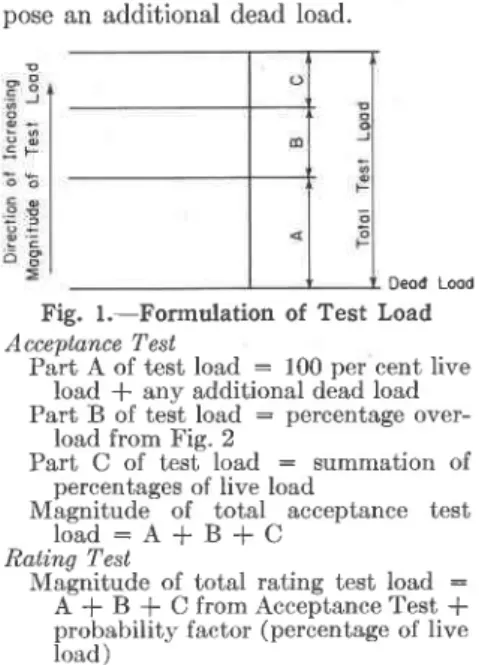
The magnitude of the test loading in an acceptance test is made up of three parts which. when added together'. make up the total test load to be applied to a given structure. The first part con-sists of the total live load plus any necessary dead load additions; the sec-ond part is a eertain minimum over-load expressed as a percentage of the total live load; the third part is an additional portion, expressed as the sum of individual percentages
repre-A S T M B U L L E T I N
senting the factors which distinguish one structure from another (I'ig. 1).
The first portion of the test loading indicated by 4 in Fig. 1 is 100 per cent of the design live load plus any addi-tional dead load which may not be sup-ported by the structure at the time of the test. If the test is required to ap-prove a change in use or occupancy of an existing structure, portion ,4 of the test load consists of the newly assigned live load only, unless renovations im-pose an additional dead load.
Deod L@d
Fig. l.-Formulation of Test Load Accentance Test
Part A of test load : 100 per cent live load * any addi[ional dead load Part B of test load : percentage
over-load from FiE. 2
Part C of test load : summation of percentages of live load
Magnitude of total acceptance test
l o a d : A + B + C
Ratinq Test
Malnitude of total rating test load : A + B + C from Acceptance Test * probability factor (percentage of live Ioad)
The second portion of the test load-ing indicated by B in Fig. 1 is a basic overload, expressed as a percentage of the live load. B depends upon the risk of failure and is a function of two inde-pendent variables, namel]r, use and occupancy (indicating the seriousness of a collapse) and the type of failure (or warning before faihrre). Figure 2 suggests a way of plotting this basic overload employing use and occupancy as an independent, variable and the tvpe , of failure as a parameter. The use and occupancy ordinates vary with in-creasing risk. The three culves corre-spond with the types of failure ex-pected and increase in severitv of per-centage of overload from type (c) to type (a). The percentage of overload to be applied to a given structure can be obtained by follor,ving the curve ap-propriate to the tlpe of failure expected to the point where the curve crosses a horizontal line through the appropriate use and occupancy. The percentage of overload is then indicated by a 'r'ertical line through this point on the curve.
The third portion of the test loacling indicated by C in Fig. 1 is the summa-tion of applicable percentages of live load which take into account the ma-terial and such factors as workmanship, deterioration, fatigue, long-term loading, impact loading, and vibration. The applicable number of percentages varies
Percentoge of Overlood to be Applied to Live Lood Fig. 2.-Acceptance Test and Rating Test Percentage of live load to be used in Part B of test load (o) Failure without warnins
(b) Failure occurring after yielding has taken place at a certain load (c) Failure to a state of unserviceabilitv at a certain load but still safe.
justifiably be allowed to occur ai the higher loadings used for the strength test.
The authors believe that not one cri-terion, but a combination of maximum deflection and minimum recovery, cou-pled with the absence ofanysignsofdis-tress in the main structural parts under the test loading, should be used as a strength requirement, whereas the stifi-ness requirement should consist of a maximum deflection and the absence of any signs of damage under one times live load.
Stifness Bequirement
Values of acceptable deflections or de-formations should be formulated in the usual way as certain allowable de-flection-span ratios, such as 5f6 of the span as commonly used for floors.
During the application of one times live load, it should be ascertained that there are no signs oI damage to either the structulal members or the archi-tectural finishes.
The actual values of acceptable de-flections and deformations would have to be selected by code writing authori-ties based on recommendations by a committee of experts.
Strength Eequirement
As already mentioned, the recovery of deflection after the removal of the total test loading is normally the most simple means of detecting whether the structuie has exceeded the yield point. If, however, the observation of recovery and of possible signs of failure is not considered to be sufficiently indicative of satisfactory structural performance, the building official may require strain and deformation measurements to be made by accepted methods at critical points of the structure to prove that no excessive strains or signs of instabilit5t are oceurring at these points.
The total test load should be sustained by the structure being tested for a minimum period of time, such as 24 hr, without any signs of structural failure. After removal of the test load the re-covery within 24 hr from the beginning of the unloading should be a minimum percentage of the deflection under the test load, for instance, 75 per cent.
If the structure does not pass this test but shows a minimum recovery of, say, 60 per cent, retesting should be allorved. Some of the residual de-flection after the first loading normally is of no serious consequence as it is due to "bedding down" at supports, joints, etc. The retesting should be started as soon as possible and the total test load should again be applied for at least 24 hr. After unloading the rebovery with-a o a E o o l P u b l i c B l d g S t o r o g e
with the type of construction and gives weight to the factors peculiar to a given structure. Values for these percentages could be listed in tabular form, giving numerical values for each of the factors just mentioned for different construc-tion materials. These values should be selected by code-writing authorities in consultation with research oreanizations and industry.
The rating test differs from the ac-ceptance test in that the magnitude of the lating test load depends upon the number of specimens represented by one test specimen. If every specimen were tested, the two tests would be identical, except that the rating test might be carlied to failure. The rating test may be conducted on the site or in . a testing laboratory. The variation in the streirgth of a given number of speci-nrens would be taken into account by a probability factor expressed in terms of a percentage of the live load and would be added to part C of the acceptance test, load. The choice of the value of this factor should be done on the basis of loading test statistics on similar mate-rials and constructions. Values for these pelcentages could be listed in tabular form for each material, giving the values to be set also by the code-writing authorities in consultation rvith research organizations and industry fol each of three conditions of sneci-men selection. The suggested member of specimens selected would be in rela-tion to three latios, namely, 1 in I (acceptance test), 1 in 10, and 1 in 100. Criteria for Assessing Structural
Adequacy
The next consideration should be how to judge whethel or not a structure has passed the acceptance or rating test. The acceptance and rating tests can be dealt with in the same manner, except for the test load (as for the rating test a higher test load is used depending on the number of specimens tested) and the fact that the rating test might be carried to failure.
May 1956
The structure must meet one or both of the requirements of strength and stiffness. According to present design procedure (that is, excluding limit de-sign), the strength requirement is met if, after the proper choice of the test loading, no point of the structure shows excessive stress (or strain) or imminent instability. Thus, in a loading test, the strains developed would have to be measured at all critical points and de-formations rvould have to be determined in compression members and other places of possible instability. In some structures, such as complicated frame-rvorks and thin-webbed members, this would call for elaborate instrumentation and is not practical in the case of the normal acceptance test because of the complications and the cost involved, and because of the possible inaccessi-bility of the critical points in the finished structure. Consequently, for the ac-ceptance test, other means of assessing structural adequacy from the strength point of view must be obtained, using (a) deformation or deflection, (b) re-covery of deflection after unloading, (c) signs of damage or distress, or a com-bination of these as a criterion.
Another question which must be de-cided is rvhether the same test loading should be used for strength and stiff-ness. This may not seem very impor-tant at first, as usually a structure should not reach yield conditions in the strength test so that we can assume that deformations are proportional to load. Thus it might seem of little con-sequence whether the deformations are measured at the design live load or at the test loading. The magnitude of the deflections at a loading correspond-ing to the design live load is of special interest however. The design specifi-cations often state a maximum de-flection under design live load. At this Ioad the structure under test should also be checked for the absence of minor damages, such as cracks in plastered ceilings or walls, as such cracks could
in the follorving 24 hr from the begin-ning of the unloading should be almost complete, say 90 per cent of the deflec-tion measured during the second load-mg.
These recovery figures should, of course, be adapted to diflerent types of construction and materials takins into . aecount such factors u. creep of the material under load.
If the amount of creep rvhich is esti-mated to develop in the structure under service conditions, is considered to be of consequence, the building official might require that the loading period be extended and that the deformations be measured at intervals under load to
fflx;1
plotting of the time deflection
Other Considerations
A number of details of the testing procedure should also be covered by a loading test specification. Among these are the required refinement and ac-curacy of the measurement of deforma-tion, the minimum and maximum age of a new structure at the time of testing, and special conditions such as the selec-tion of specimens for the rating test.
Further details of a specification might relate to the following: The Ioads should be applied in increments of a given fraction of the design live load and the deformation should be measured after each load increment has been in position for a given time. In the rating test each of the specimens should satisfy the strength and stiffness requirements. After unloading, each specimen should be reloaded and the loadins continued in regular increments untit failure occurs. The complete load deforma-tion curve and a detailed descripdeforma-tion of the way in which failure occurred should be submitted to the appropriate authority.
Conclusion
An attempt has been made in this paper to draw attentioh to,the short-comings of existing loading tbst speci-fications and to combine some principles outlined by the authors in a philosophy on loading tests which, in its broader aspects, will be in closer harmony with the present state of scientific knowledge. The authors, although conscious of the dfficulties which lie ahead in the task of evaluating the various factors and in choosing numerical values believe that the views and principles incorporated in this paper are shared by many who are interested in the safety and efficiency of structures.
The authors are encouraged in this belief by many references in papers such as those listed ai the end of this paper, and in partlcular by the following
quo-44
(TP1o2)
tation from the Report of the British Building Research Board for the year 1953.
"In recent years there has been an increasing tendency for structural engi-neers to consider a new approach to de-sign. In this, the old method of check-ing that the stresses throughout a struc-ture, for the assumed conditions of working load, are less than certain per-missible values, is largely abolished. In its place a design philosophy is being developed of which the main plinciples are (.1) that the load that rvill just cause failure of the structure is sufficiently greater than the working load, so that the probability of failure during the re-quired life of the structure is less than a specified funft, (2) that for working-load conditions through the required Iife, the deformations of the structure shall not be such as to impair its safety or efficiency, and (9) that economic considelations in the design of struc-tures shall include full allowance for the need for, and cost of, maintenance during the life of the structure." Acknowledgments:
The cooperation and assistance of D. E. Parsons, Chief, and G. N. Thomp-son, Deputy, Building Technology Di-vision, National Bureau of Standards, is gratefully acknowledged. This re-port has been prepared with the ap-proval of R. F. Legget, M.I.C.E., Di-rector of the Division of Building Re-search of the National ReRe-search Coun-cil, whose continued encorlragement and help is acknowledged.
Bmr,rocnarsy
M. A. Arnan, M. Reiner, and M. Teino-witz, "Research on Loading Tests of ll.einforced Concrete Floor Structures." The Research Council of Israel, Jeru-salem p. 54 (1950).
Arthur Lempriere Lancey Baker, "Further Research in Reinforcetl Concrete and its Application to Ultimate Load De-sign." Proceedings, Inst. Civil Engrs., Part III, VoI. 2, No. 2, August, 1953, o . 2 6 9 .
P.-J. Carroll, "The Factor of Safety as Applied to Reinforced Concrete Design." Jotnnal Inst. Civil Engrs., Vol. 36, No. 9, November, 1951, p. 491. John W. Dunham, "Design Live Loads in
Buildings." Trarnactions Am. Soc. Civil Engs., Vol. ll2, p.725 (1947). Alfred M. Freudenthal, "The Safety of
Structures." Transactions Am. Soc. Civil Engs., Vol. 112, p. r25 (19a7). Alfred M. Freudenthal, "Reflections on
Standard Specifications for Structural Design." Transactions Am. Soc. Civil E n g s . , V o l . 1 1 3 , p . 2 6 9 ( f 9 4 8 ) . G. Anthony Gardner, "The Safety Factor
in Construction." Engineering, Marc}r' 13, 1953, p. 343.
A S T M B U L L E T I N
Great Britain, Department of Scientific and Indrrstrial Research. Report o! the Build,ing Researclt Board, for the gear 1953, pp. 1G-17, London, H.M.S.O. ( 1954).
Jacques Heyman, D. T. Wright and V. L. Dutton, "The Plastic Theory of Structural Design." The Engineering Journal, Vol. 36, No. 12, December, 1953, p. 1603.
Eivind Hognestad, "Fundamental Con-cepts in Ultimate Load Design of Reinforced Concrete Members." Pro-ceed'ings, Am. Concrete Inst., Vol. 48, p . 8 0 9 ( 1 9 5 2 ) .
Housing and Home Finance Agency, "Per-forma,nce Standards." (Structural and Insulation Requirements for Houses.) Housing and Home Finance Agcncy Technical Office, Washington 25, D. C. June, l9-17.
A.Iexander Hrennikoff, "Theorv of Inelas-tic Bcnding with Reference to Limit Design." Transactions Am. Soc. Civil Engs., Vol. 113, p. 213 (1948). Arne I. Johnson, "Strength, Safety and
Economical Dimensions of Structures." Victor Petersons Boltindustri Alctiebolag, Stockholm, No. 12 (1953).
F. M. Lea and N. Davey, "The Deterio-ration of Concrete in Structures." Journal Inst. Civil Engs., Vol. 32, May, 1949 p. 248.
Hyman Levy, "The Impact of Statistics on Civil Engineering." Proceed'ings, Inst. Civil Engs., {ol. 2, No. 6, Nov-ember, 1953, p. 68t.'
National Bureau of Standards, "Mini-mum Design Loads in Building and Other Structures." Am. Standards Assocn., New York 17, N. Y. (1945), n. 19.
B.-G. Neal and P. S. Symonds, "The Cal-culation of Collapse Loads for Framed Structur:es." Journal Inst. Civil Engs., Vol. 35, No. l, November, 1950, p. 21. B. G. Ncal and P. S. Symonds, '.'The Cal-culation of Failure Loads on Plane Frames under Arbitrary Loading Pro-grammes." Journal Inst. Civil Engs., Vol.35, No. 1, November, 1950, p.41. Filadelpo Panlilio, "The Theory of Limit Design Applied to Magnesium Alloy and Aluminum Alloy Structures." Royal Aeronautical Soc'iety Journal, VoI. 51, p. 537 OsaT).
William Prager, "Limit Analysis and Design." Journal Am. Conciete Inst., Vol. 25, No. 4, December, 1953, p. 297. A. G. Pugsley, "Repeated Loading on Structures*" (In Proceed,ings of Sym-posium HeId on "The Failure of Metals by Fatigrre," in University of bourne, December 2-6, 1946. Mel-bourne), University Press, Melbourne, p . 6 a ( w a 7 ) .
A. G. Pugsley, "Concepts of Safety in Structural Engineeling." Journal oI the Inst. of Civil Engs., VoI. 36, No. 5, March, 1951, p. 5.
A. G. Pugslev, "The Behaviour of Struc-tures Under Repeated Loads." Royal Aeronautical Society Journal, Vol. 51, p. 715 (19a7).
W. Tye, "Factors of Safety-or of Habit?" Royal Aeronautical Society Journal, Vol. 48 ( 1944).
J. A. Van den Broek, "Theory of Limit Design." Transactions Am. Soc. Civil Engs., Vol. 105, p. 638 (1940). Institution of Structural Engineers. "Re;
port on Structural Safety." The Struc-tural Enpiineer, May, 1955, p. 141." o This report was published after the authors finishcd their papcr.