HAL Id: hal-02156060
https://hal.archives-ouvertes.fr/hal-02156060
Submitted on 14 Jun 2019
HAL is a multi-disciplinary open access
archive for the deposit and dissemination of
sci-entific research documents, whether they are
pub-lished or not. The documents may come from
teaching and research institutions in France or
abroad, or from public or private research centers.
L’archive ouverte pluridisciplinaire HAL, est
destinée au dépôt et à la diffusion de documents
scientifiques de niveau recherche, publiés ou non,
émanant des établissements d’enseignement et de
recherche français ou étrangers, des laboratoires
publics ou privés.
Real time and interactive co-execution platform for the
validation of embedded systems
Sara Sadvandi, Franck Corbier, Eric Mevel
To cite this version:
Sara Sadvandi, Franck Corbier, Eric Mevel. Real time and interactive co-execution platform for the
validation of embedded systems. ERTS 2018, Jan 2018, Toulouse, France. �hal-02156060�
1
Real time and interactive co-execution platform for the validation
of embedded systems
Sara SADVANDI1, Franck CORBIER2, Eric MEVEL3,
1: Dassault Systèmes, 10 rue Marcel Dassault, 92940 VELIZY, France 2: Dassault Systèmes, 35 rue Haroun Tazieff, 54320 MAXEVILLE, France
3: Dassault Systèmes, 120 rue René Descartes, 29280 Plouzané, France
Keywords
Model-based testing, Model In the Loop, Software In the Loop, Hardware In the Loop, Progressive Integration, Interface, Digital manufacturing, Cyber Physical Systems, Virtual Commissioning, Human System Interaction, Human Machine Interface(HMI), System Validation, System Under Tests, Real Time and Interactive Execution, Test Scenarios.
Abstract
The main objectives of this article are to enlighten the importance of early validation and virtual (or hybrid) co-execution in complex systems and to provide associated solution. First step is to define a common ontology as a high level conceptual organization of test based engineering and validation. As a second step, we introduce a real time and interactive co-execution platform that provides heterogeneous model integration, models validation and monitoring. We discuss about technical aspects of platform with emphasize on openness, independent and consistent integration, and system scalability. Then we analysis how such a unified testing system can be leveraged to better coordinate and optimize risk and reduce time to market for complex projects from different abstraction levels. Finally, we explain how real time and interactive co-execution may accelerate the integration tests and system validation in the context of multidisciplinary projects through a collaborative platform.
1. Introduction
In many industries such as automotive, railway, avionic, high-tech, and healthcare, we find systems consisting of multiple embedded components that collaborate to control complex physical processes and to interact with users. These “Cyber physical systems” are increasingly complex and makes their development and validation processes critical. As a heart of innovation, the dominating software
2
components as implemented on real time controllers and electronic control units. One of the major challenges in this context is to enable early virtual prototyping, collaborative co-execution and digital continuity for a faster and more efficient development and validation of the systems.
Validation of embedded systems implies dealing with complex interconnected models at different levels of abstraction and maturity. Each model offers its own perception associated to its hardware/software architecture for synthesis or co-execution. In many cases, modelling teams work in silos so validation and co-execution raise interoperability issues between abstraction levels of different tools and frameworks. In order to deal with these complexities this paper aims to introduce a solution to co-execute and validate the integration of heterogeneous models in an independent and open platform. This solution improves productivity and maintainability of complex systems by ensuring the interoperability between systems and sub systems.
This paper has two main objectives: firstly, to introduce the model based testing process and methodology for validation of complex multi-disciplinary industrial systems; secondly, to introduce a platform that provides integration, co-execution and validation of heterogeneous models in real time and interactive environment.
Testing system framework is an open and consistent platform that allows test engineers to reuse the existing multi discipline and multi domain models in order to build realistic experiences for Model In the Loop (MIL), Software In the Loop (SIL) and Hardware In the Loop (HIL) activities.
We will also discuss on effective deployment topics such as virtual commissioning, virtual and hybrid integration tests.
2. Model based testing process
Replacing physical components such as vehicles, robots, or planes, with virtual twin can remarkably reduce the cost of testing and validation of control systems, software, and hardware. The co-execution visualization also improves the quality of the final product by enabling advance validation of the entire system in early phases.
Historically, it has been proven that moving from desktop to real-time validation reduces development costs and increased quality of products. As a core element of Model-Based Design and Testing, it will continue to play an important role in product development processes.
2.1.
Model based Design and Validation
A model represents a dynamic system whose response at any time is a mathematical function based on its inputs, current state, and current time. Model Based Design refers to the use of models and modeling environments as the basis for embedded system development [12].
3
Model-Based Design is used throughout the system development life cycle and provides design flows that include progressive verification and validation of requirements, designs, and implementations. The main activities that occur during Model-Based Design include: Modeling and simulation, Quick and dirty prototyping and production code generation and integration.
2.2.
IN-THE-LOOP testing
Modeling and simulation is an early validation method. Testing models via virtual simulation is a rigorous approach used in early validation. Model testing requires a systematic approach to define test case and test execution scenarios.
In-the-loop testing techniques allow one to reuse the model test cases and test environment for execution with the production application during various stages of integration [13, 15, 20, 21].
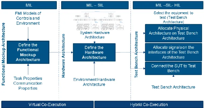
As it is illustrated in figure 1 there are three steps of testing: Model-in-the-Loop, Software-in-the-Loop and Hardware-in-the-Loop.
At the Model-in-the-Loop step, various types of models, typically functional models, can be tested. Heterogeneous models are quite abstract and don’t consider aspects such as robustness or performance. As it is seen in figure 1, MIL testing step takes into account integration of the heterogeneous models with different characteristics via Functional Mockup Architecture (FMA). In MIL step, the integrated models are validated via virtual co-execution [13, 20, and 21].
The Software-in-the-Loop testing step is software testing when the functional model becomes mature and the goal is to find errors introduced by programming activities. Source code, typically C code, is on SIL tested in a simulated environment [1, 3]. SIL step introduces the definition of the Hardware Architecture, which is allocated to the Functional Mockup Architecture (FMA) build on MIL step.
The Hardware-in-the-Loop step, software runs on final (or retargeted or re-hosted) embedded device connected with a simulated environment (actuators, sensors, and multi-physics). Communication is performing through the analog and digital interfaces of the device so these tests reveal faults in the device’s low-level I/O services. HIL testing requires test bench architecture as mentioned in figure 1 and real-time behavior of the environment so that the communication with the device is the same as in final application. Some advantages of HIL testing over testing on product level are: Tests are repeatable, can be automated, and are usually much cheaper than physical tests that encompass entire final product [2, and 3].
4
Figure 1 Different steps of test architecture
2.3.
Progressive integration and validation methodology
Progressive integration process is an ongoing validation and monitoring of all aspects of the production. The aim is to ensure that all the phases of development are controlled and regulated. In this chapter, we propose a validation methodology for progressive integration of systems based on MIL, SIL, and MIL. A co-execution and integration platform for In-The-Loop-Testing shall provide the following validation methodology and steps [5]: First, virtual co-execution in MIL step of testing as it is mentioned in figure 2 is initiated. Then virtual co-execution in SIL step (Figure 2) and finally hybrid co-execution in HIL that help to connect the virtual world to real ones.
MIL level of testing:
1. Define Functional Mockup Architecture (FMA) by assembling FMI models. a. Define test scenarios,
b. Define customized HMI,
2. Define System Under Tests (SUT) by filtering the Functional Mockup Architecture (FMA), 3. Define test experience for MIL,
5
Figure 2 MIL step of testing
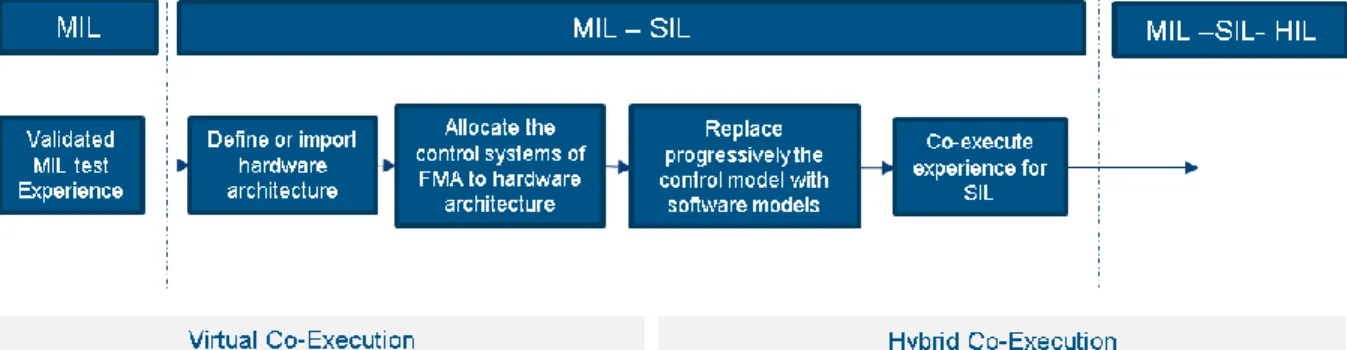
SIL level of testing (Figure 3):
1. Define or import the hardware architecture,
2. Map and allocate the control systems of FMA to hardware architecture, 3. Replace progressively the control model with software models,
4. Launch the co-execution of the experience for SIL.
Figure 3 MIL-SIL step of testing
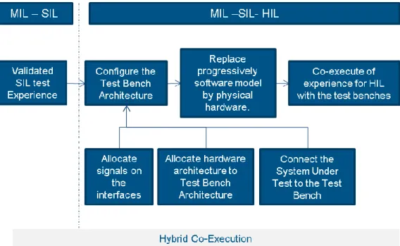
HIL level of testing (Figure 4):
1. Configure the Test Bench Architecture:
a. Allocate signals on the interfaces of the Test Bench architecture, b. Allocate hardware architecture to Test Bench Architecture,;
2. Connect the System Under Test to the Test Bench and physical hardware,
3. Replace progressively (unable and disable according to their presence) the software model by physical hardware.
6
Figure 4 MIL-SIL-HIL step of testing
3. Testing platform technical features
MIL, SIL and HIL activities need to share models while modeling itself is not new in system development. However, system engineers have inclined to work in their own particular domains–such as specification writing, design or test engineering–with their own specific tools. Usually test engineers reuse existing models coming from different teams and disciplines in order to co-execute the models in virtual or hybrid platforms within their environments. This implies an openness and independent model integration and co-execution workbench.
In this chapter, we introduce the test and validation platform that provides integration, co-execution and validation of heterogeneous models in real time and interactive environment.
The technical features of our platform are listed as follow:
FMI Standard1: FMI standard is to share models between different disciplines and tools; a standard, called Functional Mock-Up Interface (FMI), provide specifications to deliver models with well-defined interfaces and services from original models coming from different authoring tools [6, 7]. FMI facilitates collaboration between the various disciplines and allowing each team to continue to develop models and software on its specific authoring tool while cooperating in a complete and flexible system co-execution [8]. Our System Testing workbench integrates the FMI standard as input in order to make a testing experience including various kinds of IDE, languages and models [9, 10].
1
7
Heterogeneous Model Integration: The simulation designer selects the FMI models as resources of the
co-execution, then connects FMI models together using their published interfaces, and then configure values of some parameters (including execution mode and time cycle) in order to define the Functional Mockup Architecture and co-execution properties. The integrated models are simulated for a step by step validation (MIL, SIL and HIL) of the progressive integration. These compositions become new reusable models for a higher experience level of the system and for other projects.
Validation and control: To design a product just on its own is no longer sufficient. We need to design it
and experiment it in the context of the environment, and human interaction that use it, and in the context of the relationship with other systems. Our System Testing workbench allows us to not only co-execute the models but also validate their functionalities via a real time and interactive workbench.
Real Time Execution: The validation of the system depends not only on the logical result of the
computation, but also on the time at which the results are produced. Our System Testing workbench is based on real time execution in order to be compliant with performances required by the test of the physical controllers or equipment that can be connected in HIL.
Testing scenario: The platform enables development of the test procedures (scenarios) in order to
validate automatically the interactive behavior of the systems and sub-systems. In particular, on this basis, the platform allows test engineers to execute and thereby interplay one or several scenarios. The scenarios are written with user-friendly and graphical notation.
HMI interfaces: A customized user interface allows test engineers to interact with systems. It also allows
creation of virtual dashboards that are connected to different model parameters or signals that have to be displayed.
4. Related work
For many years, industries have performed systems test by using real physical systems. Due to the complexity of the embedded electronic architecture of today’s systems, and to meet stringent safety constraints, train makers now have to make integration and validation tests on virtual test benches. Each discipline knows how to validate single pieces of equipment from a given supplier one by one and it is obviously simple using light test benches. Each equipment can be running correctly in a “stand alone” mode but many errors occur when all equipment are connected together in the complete system.
System Testing workbench address three effective deployments domains:
Sub-system validation: System-testing workbench allows us to integrate heterogeneous
real-time and interactive sub-system and validate their behavior in consistent and efficient environment. It allows us to validate the whole system behavior as early as possible in the
8
development-cycle and at different abstraction levels. In many engineering organizations such as automotive, aerospace, and communications, integrating software, hardware, and mechanical components, often requires the collaboration of several teams from different domains of expertise using different development and validation tools.
System of system validation: integration of sub-system validation: A system is a group of
interacting, interrelated and interdependent components that form a complex system. Each system is verified via system Testing workbench. System Testing workbench allows us to define Functional Mockup Architecture to integrate different systems within their environment, for example a train on the rail and train station. The goal is to get maximum validation of system in its context by understanding of how each of the systems work and interact together.
Virtual commissioning: The manufacturers of industrial equipment often need to validate
dynamically the behavior of their special machines. Virtual commissioning is used to validate the whole control systems (the hardware architecture and its software) connected to a virtual model of the plant (simulation of the actuators, sensors and environment...). This mandatory test activity allows system integrator to test, in the virtual world, all the operations modes, control functionalities, fault detection and alarm management coded and integrated in the control system [16]. System Testing workbench is replicating the behavior of a physical manufacturing environment with a software system. The ultimate goal is to provide an environment for the manufacturing automation controls engineer to validate their PLC (Programmable Logic Controller) ladder logic and HMI (Human Machine Interface) models prior to system debug in the manufacturing production environment[17,18].
5. System testing impacts on project life cycle
Impact conception and specification: the specification process moves from paper approach to a model based design approach. Executable specification allows early validation and design review with both internal and external teams. This early validation significantly decreases the risks. Furthermore, the System Testing workbench allows teams to use their favorite authoring tool and integrate different nature of models in platform. Impact on implementation and design: design team can get the final solution in early phases. That enables them to start testing within a virtual twin prior to the physical system. The validation /test engineer can detect and correct number of errors earlier in the development process. Impact on validation and qualification: In industries such as automotive, aerospace, energy and, railway, the description of the test benches is no longer defined by one specific use case. The validation engineer needs to easily reconfigure the test bench depending on the current test objectives and the target to test (the System Under Test). After a huge number of projects, validation engineer have developed their own test benches and a lot of specific environment models. The System Testing workbench allows the
9
hardware of the test benches to become generic and more open and configurable to meet the various kinds of models and test cases.
Impact on development process: Test Engineers integrate different level of maturity of the control system: MIL with models of control functions, SIL with control software and HIL with physical controllers. The objective is to be able to validate the control system inside the virtual system as early as possible in the lifecycle. Progressively replacing models of equipment by representations that are more accurate and is readily possible using the FMI Standard.
6. Conclusion
Along with the growing functionality and model-based validation processes, the demands on quality assurance have increased drastically. In terms of testing, model-based validation enables systems engineers to test the system in a virtual environment before implementation or integration of the code on the final hardware.
This paper introduced the validation process, introduced a System Testing workbench for real time co-execution and, described the steps in moving from non-real-time desktop to real time co-co-execution. The System Testing workbench allows testing the virtual product at first integration level (MIL) to experiment the control model in its environment. Then go through the test of embedded software within a simulated environment model without physical hardware (SIL) and finally support (HIL) to test the embedded software on its hardware in connection with a simulated environment (actuators, sensors and physics) in the same platform.
There are several solutions providing MIL or SIL or HIL, however System Testing workbench is based on progressive validation approach via an independent integration platform. It provides continuous validation process for MIL, SIL, HIL in the same platform that is promising the productivity gains and organizational effectiveness. For the whole process, the time taken to design and implement the system is reduced significantly while also the overall quality and the safety of the systems developed have improved.
System Testing workbench is a web based solution that drastically reduces the IT cost. It provides high level of abstraction over existing process; beside it extends simulation usability to non-expert users with friendly interfaces. Furthermore, it is fully connected to the governance layer for test configuration and change management. In validation processes, test configuration may lead to automatic generation of test experience via variant, option and parameters management. System Testing workbench is a PLM
10
integrated solution that provides single source of truth and digital continuity between all levels and assets of the project life cycle.
7. References
[1] Muresan & Pitica, "Software in the Loop Environment Reliability for Testing Embedded Code", (SIITME), Alba Iulia, Romania, October 2012., pp. 325–328.
[2] Shokry& Hinchey, "Model-Based Verification of Embedded Software", Vol. 42, 2009, pp. 53–59. [3] Babic J, 2014, “Model-based approach to real-time embedded control systems development with legacy components integration”.
[4] Bringmann & Kramer, "Model-Based Testing of Automotive Systems", In 1st International Conference on Software Testing, Verification, and Validation, Lillehammer, Norway, April 2008., pp. 485–493
[5] Corbier, “Using the new Functional Mock-up Interface technology to improve the qualification of complex embedded control systems”, 2013, Embedded World Conferences.
[6] Blochwitz & all, “Functional Mock-up Interface 2.0: The Standard for Tool independent Exchange of Simulation Models”, 2012, 9th International Modelica Conference
[7] Akesson & all, “Generation of Sparse Jacobians for the FMI 2.0”, 9th International Modelica Conference2012, Kittilsen & all, “Designing models for online use with Modelica and FMI”, 9th International Modelica Conference.
[8] Schierz & all, “Co-simulation with communication step size control in an FMI compatible master algorithm”, 2012, 9th International Modelica Conference
[9] Erdelyi & all, “FMI implementation in LMS Virtual Lab Motion and application to a vehicle dynamics case”, 2012, 9th International Modelica Conference
[10] Pohlmann & all,“Generating FMU from Software Specifications”, 2012, 9th Modelica Conference, [11] Corbier, “Model Based Design and Testing of Embedded Systems for the Train & Transportation Industry”, 2012, Joint Rail Conference, Philadelphia, Pennsylvania, USA
[12] Bringmann & Kramer, April 2008, "Model-Based Testing of Automotive Systems", In 1st International Conference on Software Testing, Verification, and Validation, Lillehammer, Norway, pp. 485–493
[13] ETAS Group, "ETAS RT2: Test for Model-in-the-Loop and Software-in-the-Loop", available at: http://www.etas.com/en/products/rt2.php (16 March 2014.).
[14] Conrad & Fey, "Systematic Model-Based Testing of Embedded Automotive Software", 2005, Electronic Notes in Theoretical Computer Science, Vol. 111, pp. 13–26
[15] Board, I. S. T. Q., "A taxonomy of model-based testing", 2010, Technical report, International Software Testing Qualification Board, Editor: van VeenendaalE.
[16] Hoffmann,2010 “Virtual commissioning of manufacturing systems a review and new approaches for simplification”
[17] Kühn, "Digital Factor y - Simulation Enhancing the Product and Production Engineering Process", Proceedings of the Winter Simulation Conference WSC 06., pp. 1899-1906.
[18] Reinhart & Wünsch, "Economic application of virtual commissioning to mechatronic production systems", 2007 Production Engineering, 1, 4, pp. 371-379.
[19] Spike J, 2015, Holistic Virtual Testing and Analysis of a Concept Hybrid Electric Vehicle Mode. [20] dSPACE DS1006 Processor Board: http://www.dspace.de