HAL Id: hal-02339637
https://hal.archives-ouvertes.fr/hal-02339637
Submitted on 4 Nov 2019HAL is a multi-disciplinary open access archive for the deposit and dissemination of sci-entific research documents, whether they are pub-lished or not. The documents may come from teaching and research institutions in France or abroad, or from public or private research centers.
L’archive ouverte pluridisciplinaire HAL, est destinée au dépôt et à la diffusion de documents scientifiques de niveau recherche, publiés ou non, émanant des établissements d’enseignement et de recherche français ou étrangers, des laboratoires publics ou privés.
Screw dislocation interaction with irradiation
defect-loops in et945;-iron evaluation of cross-slip effect
using dislocation dynamics simulations
Y. Li, C. Robertson, M. Shukeir, L. Dupuy
To cite this version:
Y. Li, C. Robertson, M. Shukeir, L. Dupuy. Screw dislocation interaction with irradiation defect-loops in et945;-iron evaluation of cross-slip effect using dislocation dynamics simulations. Modelling and Simulation in Materials Science and Engineering, 2018. �hal-02339637�
1
Screw dislocation interaction with irradiation defect-loops in α-iron:
evaluation of cross-slip effect using dislocation dynamics simulations
Y. Li*, C. Robertson, M. Shukeir, L. DupuyDEN-Service de Recherches Métallurgiques Appliquées, CEA, Université Paris-Saclay, F-91191, Gif-sur-Yvette, France
Abstract
Plastic strain spreading in post-irradiated ferritic steels usually takes the form of wavy shear bands, where the mobile dislocations randomly interact with the radiation-induced, dispersed defect populations. In these conditions, it is believed that the dislocation/defect interactions are significantly affected by the ubiquitous, stochastic cross-slip mechanism. The cross-slip effect is assessed by means of specific three-dimensional nodal DD simulation setups, consistent with available experimental evidence of cross-slip activity in post-irradiation straining conditions, at room temperature. A significant, cross-slip induced reduction of the effective dislocation/loop interaction strength is thereby evidenced, for various applied stress conditions and dislocation configurations. The corresponding, local interaction mechanisms are consistent with grain scale DD simulations results, in terms of post-irradiation plastic strain spreading.
Keywords: composite screw dislocation source; radiation-induced defects; cross-slip segment; dislocation dynamics simulation
*Correspondence author
2
1. Introduction
Ferritic steels are widely used as structural nuclear materials, thereby subjected to neutron irradiation-induced degradation, including hardening and embrittlement [1]-[4]. These detrimental evolutions are concurrent with and generally ascribed to the gradual accumulation of dispersed defect cluster populations, in the form of sessile (immobile) dislocation loops. The defect dispersion characteristics, size and number density, depend on many different factors such as the irradiation temperature, cumulated dose and the material chemical composition [5]-[7]. Mobile dislocations generated during post-irradiation straining strongly interact with these loop/defect populations [8]-[11]. At the grain scale, plastic strain spreading takes the form of wavy shear bands, controlling the subsequent stress-strain and fracture toughness responses [12]-[15]. Understanding the shear-band scale plasticity mechanisms is thus a crucial factor, in the management of nuclear structural material lifetime.
Dislocation/loop interactions have been recently investigated using atomistic Molecular Dynamics (MD) [16]-Erreur ! Source du renvoi introuvable. or mesoscopic Dislocation Dynamics (DD) simulations [19]-[22]. These studies usually assume periodic boundary conditions, i.e. infinitely long mobile dislocations. Shear band development also involves the ubiquitous cross-slip mechanism, which possibly have a strong influence on the dislocation/loop interaction, with finite length (screw) dislocations [23]-[24]. Cross-slip is a time-dependent, stochastic phenomenon [25]-[28] and for this reason, its specific contribution to the effective radiation-induced loop strength has not yet been measured or
3
evaluated. Loop interaction strength assessment is attempted hereinafter, by means of DD simulations. This technique allows implementing a specific initial configuration, associated with a (screw) dislocation glide plane change, due to a single and well defined cross-slip event. That initial configuration is called a «composite dislocation source» (please refer to Fig. 1), which has been developed based on TEM observation of cross-slip activity, in post-strained ferritic steel [29]-[30]. Such evaluation is generally not accessible to any other known investigation method, including experiments. For instance, crystal plasticity cannot treat cross-slip at the scale of individual dislocation/defect interaction, unless informed by other, lower scale simulation methods. The typical time step of atomistic (molecular dynamics) simulations is generally too brief however, to generate a composite source configuration within a reasonable simulation timeframe.
The following investigation approach is therefore adopted, based on the simulation method and setups as described in Section 2. Simulations using periodic boundary conditions (without pining points) are carried out first, as a benchmarking case (Section 3.1.1:
loop case; Section 3.2.1: loop case). These results allow validating the adopted simulation parameters and setup, by comparison with well-established MD simulation results. The role of cross-slip is evaluated next, using DD simulations with “composite dislocation” sources. The results are compared with the preliminary case results: Section 3.1.2: loop case; Section 3.2.2: loop case. This paper focused on pure Fe,
taken as a model ferritic material, for which all the material parameters are well-characterized [31]-[32].
4
2. Simulation method and setups
2.1 Dislocation Dynamics simulation setup and model: benchmarking case
All DD simulations results presented in this work are performed using a 3D nodal code called NUMODIS (e.g. [19],[21]-[22]), developed in CEA. The dislocation lines are described by a series of inter-connected nodes. Computation of the internal elastic stress and corresponding nodal force is carried out within the frame of the non-singular continuum elastic theory [33]. Nodal velocity is proportional to the effective resolved shear stress, as per: eff s s b v B (1)
where τeff is the effective resolved shear stress, bs is the dislocation Burgers vector and Bs the viscous drag coefficient, characterizing the phonon scattering effect in Fe at room temperature [31]-[32],[34].
Typical ferritic steels microstructures include 1-2 µm thick sub-laths (or platelets) crystallites, formed during the first steps of the material elaboration [30],[35]. The resulting material is then subjected to tempering at intermediate temperature, which aims at relieving the internal stress and removing the impurities remaining the lath matrix, as these tend to diffuse towards the lath interfaces. The remaining impurity contain in lath crystal is then minimal and the latter can be regarded as pure Fe, as far as dislocation motion is concerned.
5
The material parameters corresponding to pure Fe, hereby used a model material, are listed in Tab. 1 below. Viscous drag coefficient Bs (10-5 Pa s) Burgers vector b(10-10 m) Shear modulus µ (GPa) Poisson ration v 8 2.54 62.9 0.43
Tab. 1. Pure Fe materials parameters at 300K [19],[31]-[32].
As a first investigation step, preliminary DD simulation results are benchmarked by comparison with MD simulations using a similar configuration as shown in Fig. 1. The simulated crystal orientations as X, Y and Z axis are parallel to the , and
directions, respectively. The DD simulated volume dimensions are: LX = 400 nm, LY = 300 nm and LZ = 400 nm, which is consistent with the shear bands thickness observed in post-irradiated materials [13],[36]. One screw dislocation source, with its Burgers vector b parallel to the Z direction, is placed at the center of the simulation volume. The total length of the source is L, which is comparable to the dimensions of the simulation volume. In all the cases, one loop/obstacle is placed at a short distance from the mobile dislocation source, as discussed in the next section and shown in Fig. 1 below.
6 (a)
(b)
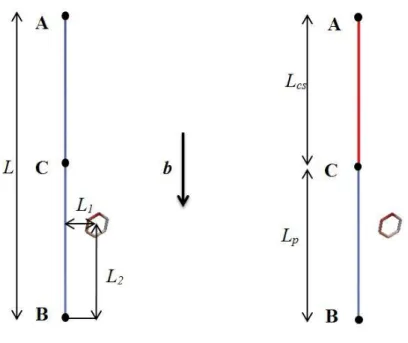
Fig. 1. DD simulation volume adapted to dislocation-loop interaction investigation. (a) This configuration has no cross-slip arm and lead to coplanar dislocation/interaction. The highlighted primary slip plane contains a screw-type dislocation source. (b) The composite dislocation source consisting of a finite length pinned source with one arm BC gliding in the primary slip plane, connected to another arm AC gliding in the cross-slip plane. This finite length configuration is compatible with TEM observations post-irradiated, strained
7
specimens [29]. The simulated space dimensions and interface properties are explained in the main text.
The complementary simulation parameters and slip systems common to all the simulation cases are listed Tab. 2:
Core-radius (A) Time step (ns)
Discretization length (A) Primary slip system Cross-slip system 2.5 0.005 10
Tab. 2. Simulation parameters
2.2 Dislocation Dynamics simulation setup and model: dislocation source cases
A composite dislocation source configuration is shown in Fig. 2. The left-hand part of Fig. 2 defines the total source length L and source-loop initial standoff distances L1, L2. The implemented loop is placed at distance L1 from segment BC and has a diameter D = 6 nm. The center of the loop is coplanar with the dislocation line and L2 = L/4 from point B (at the center of segment BC). The chosen defect position (typically 15 nm or less) ensures early contact between the dislocation and the immobile defect/loop. Small variations of L1 has a minor effect on the results since L1 << L, while the influence of L2 will be discussed in Section 3. The right-hand part of Fig. 2 shows the two segments AC and BC forming the
8
composite source. Segment AC is Lcs long which glides in the cross-slip system and segment BC is Lp long and glides in the primary slip system. The loop information is same as former case with L2 = Lp/2.
Fig. 2. Composite dislocation source configuration. Left-hand sketch: total source length L and definition of source-loop initial standoff distances L1, L2. Nodes A and B are fixed. Right-hand sketch: Segment AC is Lcs long and glides in the cross-slip plane ( ); segment BC is Lp long and glides in the primary slip plane ( ).
Nodes A and B are pinned, i.e. do not move during the simulation time similar to a Frank-Read source. Node C is the common point connecting the two segments gliding in different slip planes. For this reason, node C moves parallel to the initial direction of the dislocation line. If node C moves toward to node B, the length Lcs of segment AC increases and vice
9
versa. It should be mentioned that the non-periodic boundary condition is used for all pinned configurations and the simulation is terminated whenever a dislocation node reaches one of the simulation volume boundaries.
3. Results and discussion
3.1 Interaction with loop
3.1.1 Interaction mechanism and obstacle strength: planar dislocation source
DD simulation results obtained using periodic boundary conditions are compared with MD simulation results. In this case, controlled strain rate loading conditions (along Z direction) are used, where = 106
s-1. Interaction with the screw dislocation changes the loop Burgers vector from to b = , after the interaction is completed and the mobile dislocation breaks away from the loop (not shown). The interaction strength corresponding to this mechanism is τc = 0.4µb/(L-D), in good agreement with corresponding MD results (i.e. τc = 0.38 µb/(L-D) from [16]). The next simulation case is carried out using exactly the same strain rate as before, this time using a finite-length dislocation source (L = 300 nm), where nodes A and B are pinned (c.f. Fig. 2) and both segments AB and BC glide in the same primary slip plane ( ). The resulting interaction mechanism is presented in Fig. 3.
The screw dislocation is initially attracted by the loop and reacts with segment «2» (of the loop) to form a junction (Fig. 3(b)), according to Frank’s rule (1/2 - 1/2 = ). This particular reaction is embedded in the NUMODIS DD code, based on the
10
interaction mechanism predicted by atomistic MD simulations, in the selected case studies [17]-[18]. Thereafter, the new segments «3», «4» and the initial screw dislocation segments rearrange as shown in Figs. 3(c) (Case II) and 3(d). At this stage, the initial loop has two distinct parts, with Burgers vectors b = and b = . During the final interaction stage (Figs. 3(e), 3(f)), b = of the junction segment returns to b = .
Fig. 3(c) highlights the effect of using periodic boundary condition (Case I) on the dislocation-loop reaction. In Case I, the radius of curvature of the interacting dislocation segment is maximal. At the time of contact, the incoming screw arm can then
easily adopt and keep its b = orientation. The angle between the bowed-out dislocation segment and segment «3» is comparatively much larger (Case II). This condition lowers the attractive force between the incoming dislocation line and the remaining loop segments. The b = junction segment cannot develop in this situation
and usually collapses, after the interaction completion.
(a) (b)
Z
Y X
11
(c) (d)
(e) (f)
Fig. 3. Interaction between a coplanar, pinned screw dislocation and a sessile loop.
The screw dislocation glides in the direction of X-axis. The dislocation-loop interaction proceeds from frame (a) to frame (f). Frame (c) highlights the configurational difference achieved between the periodic boundary condition (Case I) and the composite source (Case II), shortly after the dislocation-loop contact time (corresponding to frame (b)).
12
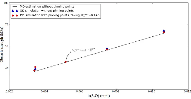
This configurational change also affects the effective loop interaction strength as shown in Fig. 4 for different source cases. The critical loop strength evolution obtained from these simulations can be described using the following expression:
1 ( ) extra c eff LT eff LT Gb L D (2)
where G is the shear modulus (see Tab. 1), b is the Burgers vector modulus, = 0.4 and = 0.42. The correction term represents the extra line tension contribution associated with the difference in local dislocation curvature (see Fig. 3(c)), due to the pinning points of the finite length source [37]-[38]. It is important to note that the screw dislocation is systematically released before adopting a semi-circular bowed-out configuration, while the loop is mostly immobile (with respect to the dislocation). As a result, the line tension correction and the loop strength (150 MPa) are both nearly constant, regardless of L2 (or Lp), within the [L/6, L/2] range (see also Fig. 7 data, for different Lp and therefore, L2 values).
13
Fig. 4. loop strength evolution with reciprocal of dislocation source length 1/(L-D).
Infinite source in presence of periodic boundary conditions: DD simulation results closely match the MD simulations results. A finite length source includes pining points, inducing dislocation curvature and hence, additional line tension stress . Eq. 2 thus illustrates the consistency of our DD model with the well-known continuum theory and MD simulation results.
3.1.2 Interaction mechanism and effective obstacle strength: composite dislocation source
The composite dislocation source case is systematically investigated with four different simulation sets, using different constant applied stress (τp, τcs) conditions and finite Lp long dislocation segments (see Tab. 3 and caption), gliding in the primary slip plane.
14 L (nm) Lp (nm) τp,min (MPa) τp,max (MPa) τp,inc (MPa) τcs,min (MPa) τcs,max (MPa) τcs,inc (MPa) Set 1 300 250 100 200 20 100 200 20 Set 2 300 200 100 200 20 100 200 20 Set 3 300 150 100 200 20 100 200 20 Set 4 300 100 100 200 20 100 200 20
Tab. 3. Simulation sets including a composite dislocation source. Each set corresponds to several different simulations, where (τp, τcs) vary by τp,inc and τcs,inc steps of 20 MPa. The selected τmin and τmax values are not arbitrary: τmin exceeds the critical source activation stress, which ensures that the mobile dislocation moves towards the immobile loop; whereas τmax exceeds the dislocation/loop breakaway stress, which ensures finding the critical interaction stress, for the different simulation setups.
Each set is tested for different τcs levels acting on segment AC and varying from (τcs,min :τcs,max) and likewise, τp levels acting on segment BC varies from (τp,min : τp,max ). Each simulation case is carried out up to a specific simulation time, tmax (typically, several nano-seconds) under a specific loading combination (τp, τcs). Once the dislocation reaches the simulation volume boundary or t = tmax a new combination (τp, τcs) is generated according to the selected stress increment. The initial loading stress is set to 100 MPa (close to the obstacle strength reported in Section 3.1.1), so segment BC (gliding in primary slip plane) contacts the obstacle at an early stage of each simulated case.
15
One typical dislocation-loop interaction case is presented in Fig. 5, for loading conditions τp = τcs = 120 MPa of set 3. Segment BC interacts with the obstacle in Fig. 5(b) and a junction is formed at the point of contact. Segment BC is then blocked since the resolved shear stress τp is lower than the critical obstacle strength (from Fig. 4: 150 MPa). Meanwhile, segment AC propagates in the cross-slip plane and its
length Lcs increases as node C moves along the line direction towards node B (Fig. 5(c)). As node C contacts with the loop/obstacle, a mutual attraction occurs between segments AC and BC then segment BC gets past the loop. Soon after, the whole dislocation source is transferred into the cross-slip plane (Fig. 5(d)). The loop is released at this time, while its Burgers vector returns to .
(a) (b)
(c) (d)
Z
Y X
16
Fig. 5. Interaction between a composite dislocation source and a loop. The source
length Lcs = 150 nm for τp = τcs = 120MPa. The mobile screw dislocation segment BC glides in the X direction. The dislocation-loop interaction proceeds from frame (a) through frame (d). Details regarding the interaction mechanism are provided in the main text.
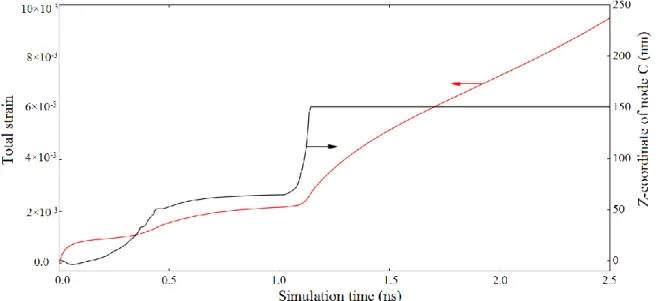
The Z-coordinate of node C (see Fig. 5) moves as described in Fig. 6. During the early stages of the interaction, node C moves towards node B and hence, the cross-slip segment length Lcs gradually increases with time. After ~ 0.5 ns, segment BC is trapped by the loop and a plateau in the strain level was observed, accordingly. As segment AC continues to glide in the cross-slip plane, segment BC then starts changing its glide plane and node C resumes gliding toward the point B until L = Lcs. As node C meets with node B, the initial source is entirely transferred in the cross-slip plane, which generates a marked strain rate jump, after ~ 1 ns.
17
Fig. 6. The total strain and the corresponding node C position evolutions with the simulation time, for the Lp = 150 nm and τp = τcs = 120 MPa case study. The initial position of node C corresponds to coordinate Z = 0.
(a) (b)
(c) (d)
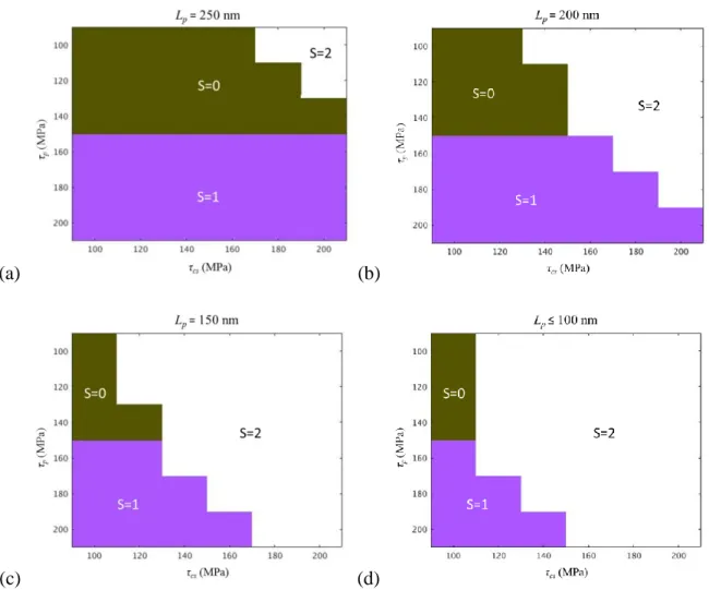
Fig. 7. Dislocation reaction case map corresponding to the constant applied stress conditions listed in Tab. 3. The x-axis refers to stress τcs acting on the cross-slip system and y-axis is the resolved stress τp acting on the primary slip plane. The 3 color codes are explained in the text. The results correspond to: (a) Set 1. (b) Set 2. (c) Set 3. (d) Set 4.
18
Simulation results associated with in Tab. 3 cases are presented in Fig. 7 in the form of triplet number series (τp, τcs, S). The S = 0 (deep green) case indicates that the source is blocked by the obstacle; the S = 1 (purple) case indicates the source overcomes the defect while gliding in the primary slip pane; the S = 2 (white) case indicates the source overcomes the defect while gliding in the cross-slip plane (as in Fig. 5). Fig. 7 shows that a screw dislocation can directly cut through the obstacle provided τp > 150 MPa which is consistent with Fig. 4 results. Obstacle by-passing occurs if τcs > τcritical(Lp) and τcs τp where τcritical(Lp) = 120 MPa if Lp = 150 nm; while Lp > 150 nm induces higher τcritical(Lp). It should be noted that τcritical(Lp = 150 nm) is lower than τcritical(Lp = 300 nm) in absence of cross-slipped segment AC, i.e. 120 MPa instead of 150 MPa.
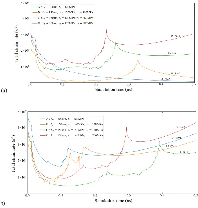
The strain evolutions corresponding to Lcs = Lp = 150 nm cases are shown in Fig. 8. Fig. 8(a) presents the time evolution of the total strain rate for τp = 120 MPa, for different τcs values ranging from 100 MPa to 180 MPa (Fig. 8(a), curves B, C, D). These results are compared with the strain rate evolution of coplanar source case, using Lp = 300 nm (Fig. 8(a), curve A). The cross-slipping time and the post-interaction strain rate strongly depend on the τcs level.
19 (a)
(b)
Fig. 8. Total strain rate evolutions versus time associated with simulation setup 3 (Lcs = Lp = 150 nm), for different loading combinations (τp, τcs). (a) τp = 120 MPa and τcs varies from 100 to 180 MPa. (b) τp = 180 MPa and τcs varies from 100 to 200 MPa. The different curves A, B, C, D are further described in the main text.
20
In Fig. 8(b) cases (τp = 180 MPa), no dislocation source blocking (strain rate = 0) is observed (see Fig. 8(a), curve A, for example). In addition, node C reaches node A for a significantly smaller τcs level, as compared to τp = 120 MPa cases in Fig. 8(a). If τcs < 160 MPa (Fig. 8(b) curve B), segment BC directly cuts through the obstacle, generating a sharp strain rate jump at t = 0.12 ns. The second peak appears as the source is entirely transferred into the primary slip plane. In the Lp = 300 nm case (Fig. 8(b) curve A), the dislocation velocity is faster due to the lack of the competition between segments AC and BC. Similarly, in τcs > τp case (Fig. 8(b), curve D), loop by-passing mechanism occurs with a slower strain evolution. The presence of the cross-slipped segment AC (for the case of
Lcs>1/3L) systematically helps the primary segment BC to get past the obstacle, including for τp and τcs levels below the critical obstacle strength (from Fig. 4: 150 MPa). This effect reduces with the decrease of the cross-slip segment length Lcs.
In order to evaluate the separate contribution of cross-slip on the dislocation-loop interaction strength, we finally replaced the loop with a hard, impenetrable platelet (or facet). The facet position, size and orientation are exactly the same as those of the
loop. The studied case corresponds to Lp = 150 nm with τp = τcs = 120 MPa. The reader should note that the implemented facet does not generate any long-range stress. The total strain and the corresponding strain rate evolutions versus the simulation time are shown in Fig. 9. In the loop case, the entire dislocation-loop interaction time is ~ 1 ns. The total reaction time is nearly the same in the facet case (~10 ps shift), with a relative total strain error of about 1.78%, at the reaction completion time. This demonstrates that the interaction with a loop is mainly controlled by the cross-slip mechanism. The reaction map (not
21
shown) corresponding to the hard facet case is exactly the same as that of the loop case (c.f. Fig. 6).
Fig. 9. Time evolutions of the total strain (upper frame) and corresponding strain rate (lower frame) during dislocation-defect interaction. The mobile segment length is Lp = 150 nm and τp = τcs = 120 MPa. The loop and facet cases are denoted by solid and dashed lines, respectively. In the loop case, the junction is formed in ①, where the mobile dislocation segment is attracted by the loop; in ②: the common node C reaches the loop; in ③: the dislocation segment is totally released by the loop; in ④: the dislocation is entirely transferred towards the cross-slip plane. For the facet case, in I: the dislocation segment by-passes the facet; in II: the dislocation is entirely transferred in the cross-slip plane. The small fluctuations taking place between I and II (or ③ and ④) are due to the discrete description of the dislocation segments (node insertion or removal).
22
3.2 Interaction with loop
3.2.1 Interaction mechanism and obstacle strength: coplanar dislocation source
The screw dislocation without pinning points and periodic boundary condition case is first examined, using fixed strain rate conditions as in section 3.1.1. In this case, the sessile loop is absorbed in the form of a helical turn [17] which then closes itself and leaves a loop is behind, as the screw dislocation breaks away. This mechanism is associated with a critical interaction stress τc = 0.72µb/(L-D) in agreement with [17].
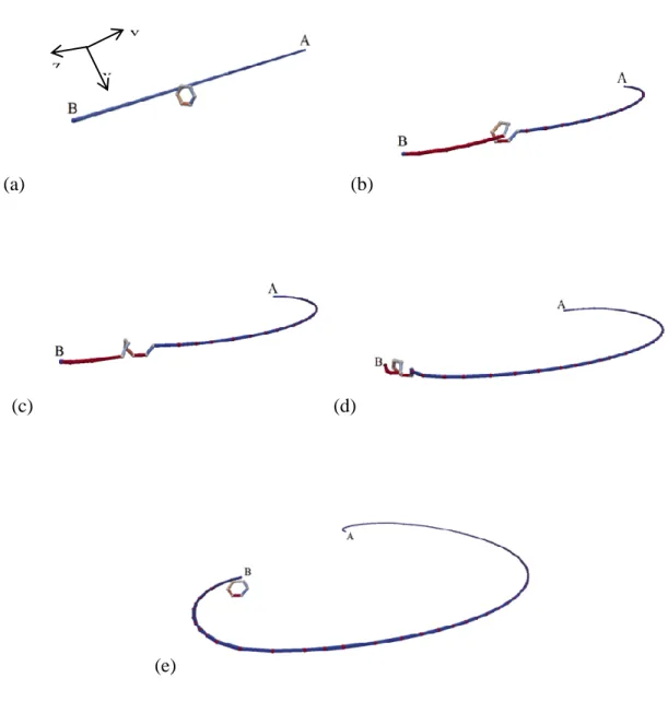
The coplanar finite-length (pinned) dislocation source case is examined next (see Fig. 10). A helical turn is formed during the first stages of the interaction (Fig. 10(b)), then after a significant bow-out of the dislocation, the helical turn reconnects and re-emits the initial loop in a process similar to Hirsch’s mechanism [39] (Fig. 10(e)). This configuration induces higher obstacle strength as compared to the loop case, owing to the larger
line tension buildup. The corresponding critical interaction stress τc = 240 MPa could be obtained from the Eq. 2 taking = 0.72 and = 0.25. It is interesting to note that the helical turns move together with the bowed-out dislocation (Figs. 10(c) and 10(d)). As a result, the obstacle strength depends on the initial position L2 (see Fig. 2). If L2 = L/2 for example, the obstacle strength τc ( + / ) µb/(L-D) for = 0.48 instead of 0.25.
This means the loop is released before the dislocation bow-out adopts a semi-circular
23
applied stress conditions (τp, τcs) are examined in the next section, for the composite dislocation source case study.
(a) (b)
(c) (d)
(e)
Fig. 10. Interaction between a coplanar pinned dislocation source and a loop. The
(screw-type) dislocation source glides in the X direction. A helical turn is formed in frame (b), which subsequently propagates towards point B, while AB segments glides and bows-out. The helical turn is released in frame (e). The interaction results in the net displacement
Z
Y X
24
of the initial loop, which is reformed near the pinning point B. the source length L = 300 nm.
3.2.2 Interaction mechanism and obstacle strength: composite dislocation source
The results associated with Lcs = 150 nm case are presented in Fig. 11. In Fig. 11(a), the critical stress range is comprised between 130 MPa and 280 MPa, in consistence with the strength of the helical turn mechanism. A fourth interaction mechanism is introduced in Fig. 11(a) (S=3, black color area), where the dislocation bow-out keeps gliding without the helical turn closure. In this case, neither AC nor BC segment can overrun the other. The helical jog is then simply dragged away, since the loop and the incoming line share the same Burgers vector. Similarly, interaction strength of the composite source is lower than that in the coplanar source case, under comparable loading conditions (see also Fig. 11(b)).
25 (b)
Fig. 11. Composite source interaction (Lcs = 150nm) with a loop. (a) The different interaction mechanisms are indicated by different color, depending on the considered applied stress (τp, τcs) combination. Mechanisms S = 0, 1, 2, 3 are explained in the main text. (b) Total strain rate evolutions versus time for τp =160 MPa and τcs varying from 130 to 220 MPa. The interaction mechanism, the cross-slipping time and the post-interaction total strain rate strongly depends on the τcs level.
Lastly, a simulation case where the loop is replaced by a oriented hard facet
(not shown) is carried out. It is recalled that unlike the loop, the facet has no associated stress field; whereas interaction with a facet involves none of the dislocation recombination mechanisms associated with loop interaction. In this way, we found that interaction with the facet is similar to interaction with a loop, as presented in Section 3.1.2. This
26
interaction strength weakly depends on the loop-induced elastic stress field or the particular dislocation-loop interaction mechanism.
3.3 General discussion
The interaction mechanisms reported in Sections 3.1.1 and 3.2.1 involve un-dissociated dislocations and strictly no cross-slip contribution. In these conditions, it can generally be assumed that these DD and MD evolutions are strain-rate independent and therefore, applicable to much slower strain rate conditions [17]-[19],[40]. The results reported in Sections 3.1.2 and 3.2.2 are obtained under constant applied stress conditions, however. In the composite-source case studies, it is important to note that the simulation time originates immediately after the glide plane change of one of the incoming, mobile dislocation arms. In usual straining conditions, this glide plane change would take place after a definite dwell time (associated with the cross-slip mechanism) which is not counted in the total reaction time reported in Figs. 8 and 11(b). Sections 3.1.2 and 3.2.2 results thus focus on the strain-rate independent steps of the interaction, which may be applicable to much slower strain rate conditions as well.
For instance, disperse defects were implemented in massive, grain scale calculations, based on high strain rate MD calculation results [17]-[18]. Grain-scale simulations were then carried out at strain rates up to 5 orders of magnitude slower. The resulting dislocation microstructures and corresponding stress-strain response are, nonetheless, fully consistent with available experimental evidence [36],[41]-[42]. This situation can be rationalized by
27
noting that most of the simulation time (or the actual, experimental time) is then spent waiting between the different cross-slip events. It is also important to note that strain reported strain rates strongly depends on the mobile dislocation density, according to the simulated space sizes. The situation is significantly different in massive DD calculations, where the mobile dislocation density is limited by interaction with various obstacles, thus limiting the mobile dislocation densities [43].
As a concluding remark, all the results presented in Section 3 were obtained using the specific, materials-dependent parameters of Section 2. It can be shown, however, that cross-slip mechanism affects dislocation/loop interactions in a wide range of BCC alloys (see for example: [29]-[30],[44]), corresponding to different sets of physical, material parameters (see Tab. 2). The reported cross-slip effect is in any case active and mainly depends on the sub-grain stress landscape, acting on the incoming (screw) dislocation arms [36],[41]-[42].
4. Conclusions
Interaction between screw-type dislocation sources with and loops is investigated using 3D nodal dislocation dynamics simulations. The comparative interaction strength levels associated with and loops are evaluated using co-planar source
cases first, where all the initial source segments glide in the same primary slip plane. Coplanar sources are used: I) infinitely long dislocation segments, due to the periodic boundary conditions, II) in the form of a finite-length, pinned dislocation segments. Case-I
28
is adopted as a benchmarking case, for validating our DD simulation model and setup by comparison with well-established MD simulations results.
1. Interaction strength associated with or loop is significantly larger in
finite-length source case II) than in periodic boundary conditions case (case-I). Pinned source nodes induce a local dislocation curvature and associated extra line tension contribution, adding up to the total effective interaction strength.
The case of composite dislocation sources is further investigated. This configuration includes two distinct (Lp, Lcs) long segments, gliding in the primary and cross-slip planes, respectively. The effect of various loading conditions (τp, τcs) on the effective interaction strength is examined, in terms of interaction mechanisms and time evolution of the strain rate.
2. The presence of a cross-slipped segment Lcs could systematically reduce the resolved shear stress needed to unpin the screw dislocation if Lcs>1/3L. The interaction strength level directly depends on the cross-slip segment length Lcs. 3. The cross-slip effect is dominant regardless of the particular loop type involved
( or ), i.e. regardless of the particular loop-induced interaction mechanism and loop-induced stress field.
In conclusion, the present results indicate that cross-slip is possibly the dominant strain rate limiting mechanism, in presence of disperse loop populations. The corresponding local interaction mechanisms are consistent with grain scale DD simulations results, in terms of post-irradiation plastic strain spreading.
29
Acknowledgements
This work has been carried out within the framework of the EUROfusion Consortium and has received funding from the Euratom research and training programme 2014-2018 under grant agreement No 633053. The views and opinions expressed herein do not necessarily reflect those of the European Commission. The complementary support of the Materials Research Program RMATE of the Nuclear Energy Division of the French Atomic Energy Commission (CEA/DEN) is also acknowledged.
30
References
[1] E.E. Bloom, The challenge of developing structural materials for fusion power systems, J. Nucl. Mater. 258 (1998) 7-17.
[2] M. Matijasevic, E. Lucon, A. Almazouzi, Behavior of ferritic/martensitic steels after n-irradiation at 200 and 300°C, J. Nucl. Mater. 377 (2008) 101-108.
[3] N. Baluc et al., Status of reduced activation ferritic/martensitic steel development, J. Nucl. Mater. 367 (2007) 33-41.
[4] M. Matijasevic, W. Van Renterghem, A. Almazouzi, Characterization of irradiated single crystals of Fe and Fe-15Cr, Acta Mater. 57 (2009) 1577-1585.
[5] Y.A. Nikolaev, A.V. Nikolaeva, Y.I. Shtrombakh, Radiation embrittlement of low-alloy steels, Int. J. Pres. Ves. Pip. 79 (2002) 619-636.
[6] R.L. Klueh et al., Embrittlement of reduced-activation ferritic/martensitic steels irradiated in HFIR at 300 °C and 400 °C, J. Nucl. Mater. 283 (2000) 478-482.
[7] M. Victorian et al., The microstructure and associated tensile properties of irradiated fcc and bcc metals, J. Nucl. Mater. 276 (2000) 114-122.
[8] S.J. Zinkle, Y. Matsukawa, Observation and analysis of defect cluster production and interactions with dislocations, J. Nucl. Mater. 329 (2004) 88-96.
[9] B.C. Masters, Dislocation loops in irradiated iron, Phil. Mag. 11 (1965) 881-893.
[10] T.S. Byun, N. Hashimoto, K. Farrell, Temperature dependence of strain hardening and plastic instability behaviors in austenitic stainless steels, Acta Mater. 52 (2004) 3889-3899.
[11] J.S. Robach et al., In-situ transmission electron microscopy observations and molecular dynamics simulations of dislocation-defect interactions in ion-irradiated copper, Phil. Mag. 83 (2003) 955-967.
31
[12] Q. Wei et al., Evolution and microstructure of shear bands in nanostructured Fe, Appl. Phys. Lett. 81 (2002) 1240-1242.
[13] G.R. Odette et al., Modeling the multiscale mechanics of flow localization-ductility loss in irradiation damaged bcc alloys, J. Nucl. Mater. 307 (2002) 171-178.
[14] J. Chaussidon et al., Internal stress evolution in Fe laths deformed at low temperature analysed by dislocation dynamics simulations, Modell. Simul. Mater. Sci. Eng. 18 (2010) 025003.
[15] J. Chaussidon et al., Dislocation dynamics simulations of plasticity in Fe laths at low temperature, Acta Mater. 56 (2008) 5466-5476.
[16] X.Y. Liu, S.B. Biner, Molecular dynamics simulations of the interactions between screw dislocations and self-interstitial clusters in body-centered cubic Fe, Scripta
Mater. 59 (2008) 51-54.
[17] D. Terentyev, D.J. Bacon, Y.N. Osetsky, Reactions between a ½ <111> screw dislocation and <100> interstitial dislocation loops in alpha-iron modelled at atomic scale, Phil. Mag. 90 (2010) 1019-1033.
[18] D. Terentyev et al., Simulation of the interaction between an edge dislocation and a <100> interstitial dislocation loop in α-iron, Acta Mater. 56 (2008) 5034-5046.
[19] X.J. Shi et al., Interaction of <100> dislocation loops with dislocations studied by dislocation dynamics in α-iron,J. Nucl. Mater. 460 (2015) 37-43.
[20] J.R. Greer, C.R. Weinberger, W. Cai, Comparing the strength of fcc and bcc
sub-micrometer pillars: Compression experiments and dislocation dynamics
simulations, Mater. Sci. Eng. A , 493 (2008) 21-25.
[21] J. Drouet et al., Dislocation dynamics simulations of interactions between gliding dislocations and radiation induced prismatic loops in zirconium, J. Nucl. Mater. 449 (2014) 252-262.
32
[22] J. Drouet et al., A direct comparison between in-situ transmission electron microscopy observations and Dislocation Dynamics simulations of interaction between dislocation and irradiation induced loop in a zirconium alloy, Scripta Mater. 119 (2016) 71-75.
[23] C.S. Shin et al., Dislocation-impenetrable precipitate interaction: a three-dimensional discrete dislocation dynamics analysis, Phil. Mag. 83 (2003) 3691-3704.
[24] A. Kelly, R.B. Nicholson, Strengthening method in crystals, First ed., Elsevier, New York, 1971, p. 156.
[25] J. Chaussidon, M. Fivel, D. Rodney, The glide of screw dislocations in bcc Fe: Atomistic static and dynamic simulations, Acta Mat. 54 (2006) 3407-3416.
[26] W. Puschl, Models for dislocation cross-slip in close-packed crystal structures: a critical review, Prog. Mater. Sci. 47 (2002) 415-461.
[27] A.A. Kelly, K.M. Knowles, Crystallography and Crystal Defects, Second Ed., John Wiley & Sons, United Kingdom, 2012.
[28] V. Bulatov, W. Cai, Computer simulations of dislocations, First Ed., Oxford University Press, New York, 2006.
[29] C. Robertson, E. Meslin, Experimental analysis of the plastic behavior of ion-irradiated bainitic RPV steel, Euratom 7th PCRD, Project PERFORM60, December 2011.
[30] C.F. Robertson, K. Obrtlik, B. Marini, Dislocation structures in 16MND5 pressure vessel steel strained in uniaxial tension at different temperatures from -196°C up to 25°C, J. Nucl. Mater. 366 (2007) 58-69.
[31] V.I. Alshits, V.L. Indenbom, Mechanisms of dislocation drag, F.R.N. Nabarro Ed., Dislocations in solids, Volume 7, chapter 34, Elsevier, Amsterdam, 1986.
[32] N. Urabe, J. Weertman, Diloscation mobility in potassium and iron single crystals, Mater. Sci. Eng. 18 (1975) 41-49.
[33] W. Cai et al., A non-singular continuum theory of dislocations, J. Mech. Phys. Solids 54 (2006) 561-587.
33
[34] G. Po et al., A phenomenological dislocation mobility law for bcc metals, Acta Mater.
119 (2016) 123-135.
[35] S. Renevey et al., Ductile - brittle transition of ferritic steels modelled by the local approach to fracture, J. Phys. IV 6 (1996) C6-343.
[36] K. Gururaj, C. Robertson, M. Fivel, Channel formation and multiplication in irradiated FCC metals: a 3D dislocation dynamics investigation, Phil. Mag. 95 (2015) 1368-1389.
[37] A.J.E. Foreman, The bowing of a dislocation segment, Phil. Mag. 15 (1967) 1011-1021.
[38] D. Hull, D.J. Bacon, Introduction to dislocations, Fourth Ed., Elsevier, Butterworth-Heinemann, 2001.
[39] P.B. Hirsch, In Vacancies' 76. Proceedings of a conference on 'point defect behavior and diffusional processes' organized by the Metals Society and held at The Royal Fort, University of Bristol, on 13-16 September, 1976.
[40] T. Nogaret, C. Robertson, D. Rodney, Atomic-scale plasticity in the presence of Frank loops, Phil. Mag. 87 (2007) 945-966.
[41] K. Gururaj, C. Robertson, M. Fivel, Post-irradiation plastic deformation in bcc Fe grains investigated by means of 3D dislocation dynamics simulations, J. Nucl. Mater. 459 (2015) 194-204.
[42] Y. Li, C. Robertson, Irradiation defect dispersions and effective dislocation mobility in strained ferritic grains: A statistical analysis based on 3D dislocation dynamics simulations, J. Nucl. Mater. 504 (2018) 84-93.
[43] A. Arsenlis et al., A dislocation dynamics study of the transition from homogeneous to heterogeneous deformation in irradiated body-centered cubic iron, Acta Mater. 60 (2012) 3748-3757.
34
[44] K. Farrell, Mapping flow localization process in deformation of irradiated reactor structural alloys-final report, Nuclear Energy Research Initiative Program No. MSF99-0072, ORNL, 2003.
![Tab. 1. Pure Fe materials parameters at 300K [19],[31]-[32].](https://thumb-eu.123doks.com/thumbv2/123doknet/12903877.371731/6.918.228.694.281.433/tab-pure-fe-materials-parameters-at-k.webp)