HAL Id: in2p3-03061436
http://hal.in2p3.fr/in2p3-03061436
Submitted on 14 Dec 2020
HAL is a multi-disciplinary open access
archive for the deposit and dissemination of
sci-entific research documents, whether they are
pub-lished or not. The documents may come from
teaching and research institutions in France or
abroad, or from public or private research centers.
L’archive ouverte pluridisciplinaire HAL, est
destinée au dépôt et à la diffusion de documents
scientifiques de niveau recherche, publiés ou non,
émanant des établissements d’enseignement et de
recherche français ou étrangers, des laboratoires
publics ou privés.
Distributed under a Creative Commons Attribution| 4.0 International License
H Podlech, K Kümpel, S Lamprecht, N Petry, P Schneider, T. Junquera, H.
Höltermann, U. Ratzinger, F. Senee, D. Uriot, et al.
To cite this version:
H Podlech, K Kümpel, S Lamprecht, N Petry, P Schneider, et al..
The MYRRHA project.
North American Particle Accelerator Conference (NAPAC 2019), Sep 2019, Lansing, United States.
pp.THZBA2, �10.18429/JACoW-NAPAC2019-THZBA2�. �in2p3-03061436�
THE MYRRHA PROJECT
∗H. Podlech
†, K. Kümpel, S. Lamprecht, N. F. Petry, P. P. Schneider,
Goethe University, Frankfurt, Germany
T. Junquera, ACS, Orsay, France
H. Höltermann, U. Ratzinger, Bevatech GmbH, Frankfurt, Germany
F. Senee, D. Uriot, CEA Saclay, Saclay, France
A. Apollonio, J. A. Uythoven, CERN, Geneva, Switzerland
R. Modic, Cosylab, Ljubljana, Slovenia
A. E. Pitigoi, P. Fernandez Ramos, Empresarios Agrupados, Madrid, Spain
F. Bouly, Univ. Grenoble Alpes, Grenoble, France
C. Zhang, GSI Helmholtzzentrum für Schwerionenforschung GmbH, Darmstadt, Germany
M. Abs, J. Brison, IBA, Louvain-la-Neuve, Belgium
J.-L. Biarrotte, C. Joly, D. Longuevergne, IPNO, CNRS, Orsay, France
A. Bechtold, NTG GmbH, Gelnhausen, Germany
C. Angulo, J. Belmans, F. Doucet, A. Gatera, F. Pompon, A. Ponton, D. Vandeplassche,
SCK•CEN, Mol, Belgium
Abstract
The main objective of MYRRHA (Multi-purpose hybrid Research Reactor for High-tech Applications) at SCK•CEN, the Belgian Nuclear Research Centre, is to demonstrate the large scale feasibility of nuclear waste transmutation using an Accelerator Driven System (ADS). It is based on a high power cw operated 600 MeV proton Linac with an average beam power of 2.4 MW. Due to the coupling of the accel-erator with a fast reactor, a major concern is reliability and availability of the accelerator. Only 10 beam trips longer than 3 s are allowed per 3-month operation cycle, resulting in an overall required Mean Time Between Failure (MTBF) of at least 250 hours. The MYRRHA Linac consists of a room temperature 17 MeV Injector based on CH-cavities and the superconducting main Linac using different RF structures as Single Spokes, Double-Spokes and elliptical cavities. In 2017 it has been decided to stage the project and to start with the construction of a 100 MeV Linac (Injector and Single Spoke section) including a 400 kW proton target station. This facility will be operational in 2026 aiming to evaluate the reliability potential of the 600 MeV Linac. The Front-End consisting of an ECR source, LEBT and 1.5 MeV RFQ is already operational while the first 7 CH-cavities are under construction. The presentation gives an overview about the MYRRHA Project, its challenges and the status of construc-tion and testing.
INTRODUCTION
The Belgian nuclear research centre SCK•CEN has been working for several years on the development of an accelerator-driven multi-purpose neutron source to replace the ageing BR2 reactor. This project, known as MYRRHA,
∗Work supported by the European Commission Framework Programme H2020, MYRTE project No. 662186
couples a high power proton accelerator with a fast 50-100 MWth reactor [1]. The 600 MeV beam delivered by
the accelerator hits a liquid metal spallation target (Pb-Bi). A focus of MYRRHA is the demonstration of the large-scale feasibility of nuclear waste transmutation. In addi-tion, far-reaching possibilities open up in materials research, component testing and the production of radioisotopes. Fur-thermore, it is planned to make part of the beam available for an ISOL-target. The MYRRHA accelerator must be able to deliver the 600 MeV beam with a beam current of up to 4 mA in cw operation with a beam power of up to 2.4 MW. Particular attention was paid to the reliability of the accelerator. The MTBF shall be at least 250 hours. This was also taken into account in the design of the accelera-tor. The design philosophy was that the accelerator should be as conservative as necessary and as efficient as possi-ble. This applies to both the hardware components and the beam dynamics. The latter is particularly important with regard to methods for increasing reliability (Dynamic Fault Compensation Scheme) [2]. In a first step the construction of the MYRRHA Linac up to an energy of 100 MeV has started. In parallel, a proton target facility (PTF) will be built to use the beam for first experiments from 2026 [3]. This first stage of MYRRRHA is named MINERVA. Ta-ble 1 summarizes the top level requirements for MYRRHA and MINERVA. The development of the MYRRHA project has been supported in recent years by various funding pro-grammes from the European Union between 2001 and 2019 (PDS XT-ADS, Eurotrans, MAX, MYRTE). In 2016 the decision was taken to divide the MYRRHA project into different phases. Phase 1 (2019-2026) includes the design and commissioning of MINERVA and further R&D on the 600 MeV Linac. Phase 2 includes the construction of the Linac up to 600 MeV and phase 3 the reactor. At a later stage it will be decided whether phase 2 and phase 3 will be executed sequentially or in parallel [3]. The reasons for this
Content from this w ork ma y be used under the ter ms of the CC B Y 3.0 licence (© 2019). An y dis tr ibution of this w ork mus t maintain attr ibution to the author(s), title of the w ork, publisher , and DOI
Table 1: MINERVA and MYRRHA Top-level Requirements
Parameter MINERVA MYRRHA
Particle type Protons Protons Frequency (MHz) 176.1-352.2 176.1-704.4 Peak beam current (mA) 4 4 Final energy (MeV) 100 600 Beam duty factor (%) 2·10−4-100 2·10−4-100 Beam power (MW) 0.4 2.4
approach are to construct, test and operate a representative section of the MYRRHA accelerator with MINERVA. This is particularly important with respect to reliability of the MYRRHA Linac and to demonstrate the feasibility of fault compensation.
RELIABILITY AND FAULT TOLERANCE
If the MYRRHA reactor is operated in subcritical mode, the spallation target provides the necessary external neutrons. If the beam is interrupted, the reactivity of the reactor core and its temperature drops rapidly. In order to minimize ther-mal stress and thus long-term damage and material fatigue, especially to the fuel rods, unwanted beam interruptions must be avoided as far as possible. This has serious con-sequences for the required reliability of the accelerator. In the operational MYRRHA context, the beam is considered to fail if its delivery to the subcritical core is interrupted during a time period that lasts longer than 3 s [4]. Such a beam interruption leads to the shutdown of the reactor, which takes several hours to restart. Frequent interruptions would drastically reduce the availability of the entire facility. To achieve an availability of 80%, the present provisional limit for the number of allowable beam interruptions of t>3 s is 3 per month. It should be noted that shorter beam trips are tolerated at a virtually unlimited occurrence frequency. A number of measures are necessary to achieve the required reliability of the MYRRHA Linac. Basically, all compo-nents have been developed conservatively, so that they are operated well below their physical limits. Examples are the minimization of thermal stress in the normal conducting cavities and the gradients in the superconducting cavities. In addition, the MYRRHA accelerator has been designed to be fault tolerant. Fault tolerance means that the function of a faulty element (e.g. amplifier module or cavity) can be taken over by one or more other elements in order to continue to deliver the proton beam with nominal parame-ters to the target. The basic precondition for a high degree of fault tolerance is redundancy. Redundancy can be en-sured in parallel or in series. To be noted that in the case of parallel redundancy one or more independent systems can provide the requested functionality. In series redundancy, the requested functionality of a given element is ensured by means of dynamic failure compensation by non-failed elements, taking over the load of the failed one. This implies that all elements must be operated well below their nominal
performance. Nevertheless, there’s a maximum number of failure cases that can be compensated thanks to the available margins. In the low energy section up to 17 MeV, two injec-tors are currently planned to ensure parallel redundancy. In the medium- and high-energy section, serial redundancy is used by means of the Dynamic Fault Compensation Scheme. If a superconducting cavity fails, other cavities will be ad-justed in phase and gradient in such a way that the failure is compensated and the beam interruption is avoided [4]. This requires powerful and low-error diagnostics (e.g. beam, RF, vacuum) in order to be able to detect failures reliably and quickly or predict their future occurrence. Furthermore, a fast Low Level RF (LLRF) system is required to recon-figure the compensating cavities with respect to phase and amplitude. Simulation tools running in parallel to support optimization of the new configuration. Additionally, it is mandatory to implement a powerful and fast control system to reach the required reliability level [5].
BEAM DYNAMICS
Beam dynamics plays a major role in the design of MYRRHA. It is obvious that beam loss of a 600 MeV Linac with an average beam power of 2.4 MW should be as low as possible to prevent possible damage to components and to minimize activation. In addition, excessive beam loss can re-sult in a shut down and lower availability of the facility. The
Figure 1: End-to-end simulation of the MYRRHA Linac with errors and cavity failures (cumulated particle density x-and z-plane).
Linac should provide large acceptance and high flexibility in tuning for normal operation as well in case of cavity failures. Extensive beam dynamics studies have been performed to optimize the Linac and to find best strategies in case of cav-ity failures. End-to-end simulations have been done using realistic 3D field maps. In addition, error studies have been performed. These studies lead to an estimation of required number of additional elements as steerer and slits. An error study with failing cavities has been performed simulating 1000 linacs with 3·106particles each. Figure 1 shows a cu-mulative plot of all linacs. 90% of the linacs do not show any losses, 99% have maximum losses below 0.2 W/m. The maximum loss of the worst case was 0.85 W/m.
A major concern is the longitudinal dynamics because it can lead to uncontrolled beam loss along the Linac. The Dy-namic Fault Compensation Scheme seems to be necessary to achieve the reliability goals but there is a drawback. It could be shown that the longitudinal acceptance is shrinking
Content from this w ork ma y be used under the ter ms of the CC B Y 3.0 licence (© 2019). An y dis tr ibution of this w ork mus t maintain attr ibution to the author(s), title of the w ork, publisher , and DOI
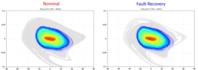
Figure 2: Example of the decrease of longitudinal accep-tance (gray shaded area) due to the compensation of failing cavities (Spoke cavity #19, full cryo module #7 in section 2, one cavity in cryo-module #10 in section 3).
when this scheme is applied. This effect is all the greater the more cavities are failing. However, multi-cavity failures and even the loss of a complete cryo module in the high en-ergy section can be compensated with enough longitudinal acceptance. Figure 2 shows the longitudinal acceptance for nominal operation and in exemplary case of cavity failures (4 cavities in total). It is clearly visible, that some parts of the beam halo are outside the acceptance. For this simulation 108macro particles have been simulated.
17 MeV INJECTOR
The injector serves to accelerate the beam to an energy of 17 MeV. It consists of an ECR source, a magnetic Low Energy Beam Transport (LEBT), a 4-Rod RFQ, a Medium energy Beam Transport (MEBT) and a total of 17 normal conducting CH-cavities. Originally it was planned to use superconducting CH-cavities above 6 MeV. Due to the deci-sion for the construction of MYRRHA and the tight sched-ule, it was decided to realize the injector completely with normal conducting cavities. Before the availability of the buildings at SCK•CEN in Mol, the first part of the injector up to 5.9 MeV is presently being installed at the Cyclotron Resource Centre in Louvain-la-Neuve. Figure 3 shows the layout of the first part of the injector.
Figure 3: Layout of the MYRRHA injector up to 5.9 MeV which is presently being under construction.
Front-End
The Front-End consists of the proton source and a LEBT-section with integrated chopper system. As proton source an ECR source has been chosen because of their high reliability, easy handling and maintenance and because of its high pro-ton fraction. The extraction energy has been set to 30 keV. This value is high enough for the beam transport and low enough to achieve a sufficiently high bunching efficiency in the RFQ. The M1000 source can deliver up to 20 mA.
In the LEBT section which has been developed by LPSC Grenoble there a two solenoids for focusing the proton beam, cleaning the beam from unwanted species (H2+, H3+) and
for matching the beam into the acceptance of the RFQ [6]. Between the solenoids various diagnostics devices (Faraday
Figure 4: The MYRRHA Front-End with ECR source and LEBT.
cups, ACCT, Allison scanner) are installed to monitor the beam properties. Motorized collimators are used to inter-cept the beam halo and to control the beam current. In front of the RFQ a chopper system has been installed to create a pulse structure required for commissioning and monitoring the sub-criticality of the reactor. Figure 4 shows the setup of the Front-End.
The Front-End has been fully characterized at LPSC. It could be shown that the transverse emittance ϵR M S, N is less than
0.2π mm mrad at the RFQ entrance as required [6]. Figure 5 shows the beam current through the tuned LEBT as function of the solenoid currents. The red dot indicates the working point where the beam is matched to the RFQ. Meanwhile the Front-End has been shipped to Louvain-la-Neuve and first tests have started.
Figure 5: Measured beam current through the tuned LEBT as function of the solenoid currents. The red dot indicates the working point.
RFQ
As first accelerating structure a 4-Rod RFQ has been cho-sen because of the excellent possibilities of frequency and field tuning, the modular design and the possibilities for maintenance and repair. In recent years, the 4-Rod RFQ has been further developed in terms of high duty cycle up to cw operation [7]. New fabrication technologies have been developed to optimize the cooling. The RFQ accelerates the beam from 30 keV to 1.5 MeV at a frequency of 176.1 MHz. To limit the thermal load, a rather low electrode voltage of
Content from this w ork ma y be used under the ter ms of the CC B Y 3.0 licence (© 2019). An y dis tr ibution of this w ork mus t maintain attr ibution to the author(s), title of the w ork, publisher , and DOI
Figure 6: The MYRRHA RFQ with open lid (left) and the setup for the high power test in Louvain-la-Neuve (right).
44 kV has been used. The shunt impedance is 73 kΩm re-sulting in a specific power requirement of 26.5 kW/m, the total RF power without beam loading is 107 kW. 4-Rod RFQ-structures have an intrinsic dipole component. In case of the MYRRHA RFQ this dipole component could be reduced from 25% to -4% by asymetric widening of the stems [8]. Figure 6 shows the RFQ with open lid and the setup for the high power tests. After a pre-conditioning with 10 kW at
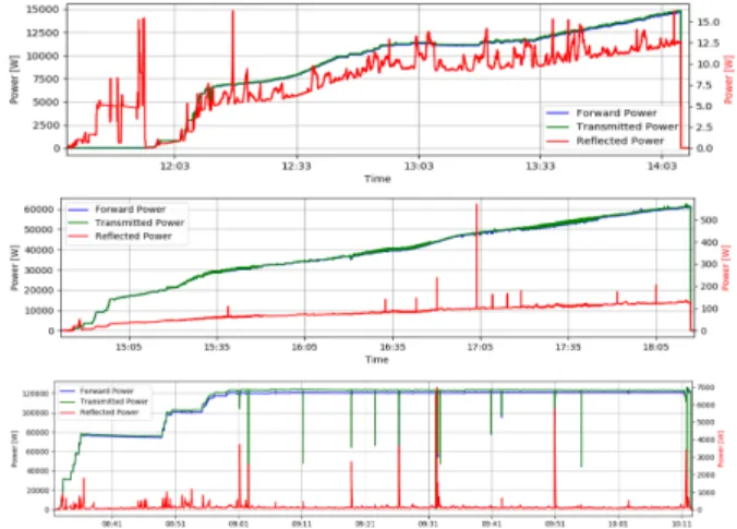
Figure 7: Exemplary measurements of the RFQ during the high power tests.
IAP [9] the RFQ was shipped to Louvain-la-Neuve. Mean-while the RFQ is conditioned with a power of up to 145 kW cw. Figure 7 shows exemplarily the conditioning of the RFQ. The belgian company IBA has developed the solid state am-plifier for the RFQ (Fig. 8). The amam-plifier delivers up to 192 kW of RF power. With respect to reliability, Solid State Amplifiers (SSA) have a great advantage because of their modular design and thus increased redundancy (RF modules, power supplies). In early 2020 first beam tests are foreseen.
CH-DTL
After the RFQ the beam is injected into a short Medium Energy Beam Transport (MEBT) section to match it into the acceptance of the following drift tube Linac. It consists of two quarter wave rebunchers, transverse focusing elements and various beam diagnostics devices. The rebunchers have been produced and are presently high power tested. The drift tube Linac has to accelerate the beam to an energy of 16.6 MeV. Basically, the Linac should be as efficient as possible in terms of power consumption. Furthermore, beam
Figure 8: 192 kW Solid State Amplifier driving the MYRRHA RFQ.
dynamic aspects, modularity, maintenance, repair, R&D ef-fort, availability of suitable amplifiers and investment costs also play a role. It has been decided to use normal conduct-ing CH-cavities operated at 176.1 MHz [10]. CH-cavities are efficient RF structures operated in the TE211mode [11].
They offer excellent cooling possibilities. All cavities are made from stainless steel with subsequent copper plating. Each cavity is equipped with one static and one dynamic tuner. Due to the cw operation, power consumption and cooling is a major issue. A prototype cavity has been tested with full power before the construction of the MYRRHA cavities has started [12].
The Design of the CH-Linac was driven by two main
fac-Figure 9: Energy gain, gap voltages and synchronous phase along the CH-Linac.
tors, applicable gradients (RF power, cooling) and beam dynamics, especially longitudinally. In many cases, H-mode structures (CH, IH) are using KONUS beam dynamics which often leads to a significant emittance growth in the longitu-dinal plane. Although it is less efficient, it has been decided to apply a conservative beam dynamics with constant
syn-Content from this w ork ma y be used under the ter ms of the CC B Y 3.0 licence (© 2019). An y dis tr ibution of this w ork mus t maintain attr ibution to the author(s), title of the w ork, publisher , and DOI
chronous phase in each cavity. The RF phase and the number of accelerating cells have been optimized to minimize the emittance growth. Figure 9 shows the energy along the Linac, the gap voltages and the synchronous phase in the different cavities. In total 15 CH-cavities are used to accelerate the beam. Between cavity 7 and 8 there is a diagnostics section and a 5-gap CH-cavity acting as rebuncher. The CH-Linac is realized by a quasi-periodic lattice. There are magnetic quadrupole doublets between the cavities for transverse fo-cusing. The quasi-periodicity leads to a smooth course of the phase advance and thus to low emittance growth. Two
Figure 10: CH-1 (left), CH-2 (center) and high power test stand (right).
CH-cavities have been produced already. After low level RF characterization the cavities have been tested with full power at IAP. The power level could be reached within a few days without problems. Figure 10 shows CH-1 and CH-2 and the setup at the high power test stand [13].
SUPERCONDUCTING LINAC
The superconducting Linac consists of an array of inde-pendently phased cavities with moderate energy gain per cavity (small number of cells and very conservative accelerat-ing gradients) [14] [15]. This increases the tunaccelerat-ing flexibility as much as possible and creates sufficient margin for the im-plementation of the Dynamic Fault Compensation Scheme. Three different cavity families are planned to cover the entire energy range from 17 MeV to 600 MeV: Single and double spokes (ESS type) cavities at 352.2 MHz and 5-cell elliptical cavities at 704.4 MHz (β=0.7). Compared to the previous design [14], it was decided to use the ESS double-spoke cavities in section 2 instead of elliptical cavities with β=0.5 in order to reduce the number of cavities and to increase longitudinal acceptance. For the 100 MeV MINERVA Linac, the first MYRRHA section, consisting of 60 spoke cavities (β=0.35)will be completely constructed.
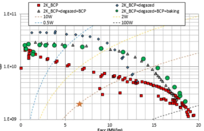
Two 352.2 MHz, β=0.35 Spoke cavities have been con-structed and tested (see Fig. 11) [16]. Special attention has been paid to the optimization of the surface preparation. The best recipe is BCP+heat treatment without any post BCP treatment. So we demonstrated that, even with a titanium tank, this post BCP is not required and moreover better per-formances are obtained in term of Q0[17]. But this implies
additional care during heat treatment by installing Nb caps on cavity openings. At low fields, unloaded Q-values be-tween 4 and 5·1010and gradients of 20 MV/m and 14 MV/m
could be achieved (see Fig. 12) [16]. All prototypes are
Figure 11: Sectional view of the β=0.35 spoke cavity (left) and realized protoype with helium vessel (right).
far above the requirements for MYRRHA and offer enough margin to compensate for the failure of individual cavities.
Figure 12: Experimental results of the spoke prototype cavi-ties.
CONCLUSION
In the MYRRHA project, a 600 MeV, 2.4 MW proton linac will be coupled with a fast reactor. The Linac will have to meet special reliability requirements. The high required reliability had a big influence on the design of the accelerator. An overall conservative approach with high modularity was pursued. It was decided to divide the project into several phases, the first of which, called MINERVA, is currently under construction. First beam tests are foreseen in early 2020. The 100 MeV Linac with target facility is the most critical part of the MYRRHA accelerator. Goals are the demonstration of its reliability and the optimization of tuning procedures due to component failures. In addition, this facility will allow a wide range of experiments to be carried out before MYRRHA is completed.
REFERENCES
[1] H. Ait Abderrahim et al., “MYRRHA, a Multipurpose hY-brid Research Reactor for High-end Applications,” Nuclear
Physics News, vol. 20, no. 1, pp. 24–28, Mar. 2010, doi: 10.1080/10506890903178913
[2] J.-L. Biarrotte and D. Uriot, “Dynamic compensation of an rf cavity failure in a superconducting linac,” Phys. Rev. ST
Content from this w ork ma y be used under the ter ms of the CC B Y 3.0 licence (© 2019). An y dis tr ibution of this w ork mus t maintain attr ibution to the author(s), title of the w ork, publisher , and DOI
Accel. Beams, vol. 11, no. 7, p. 072803, Jul. 2008. doi:10. 1103/PhysRevSTAB.11.072803
[3] H. Ait Abderrahim et al., “Myrrha accelerator driven system programme: recent progress and perspectives,” Izvestiya
vu-zov. Yadernaya Energetika, vol. 2019, no. 2, pp. 29–42, Jun. 2019. doi.org/10.26583/npe.2019.2.03
[4] F. Bouly, J.-L. Biarrotte, and D. Uriot, “Fault Tolerance and Consequences in the MYRRHA Superconducting Linac”, in Proc. LINAC’14, Geneva, Switzerland, Aug.-Sep. 2014, paper MOPP103, pp. 297–299.
[5] R. Modic, G. Pajor, K. Zagar, L. Medeiros-Romao, R. Salemme, and D. Vandeplassche, “Control System Design Considerations for MYRRHA ADS”, in Proc. IPAC’14, Dres-den, Germany, Jun. 2014, pp. 3162–3164. doi:10.18429/ JACoW-IPAC2014-THPRO115
[6] F. Bouly et al., “Commissioning of the MYRRHA Low Energy Beam Transport Line and Space Charge Com-pensation Experiments”, in Proc. IPAC’17, Copenhagen, Denmark, May 2017, pp. 1226–1229. doi:10.18429/ JACoW-IPAC2017-TUOBA2
[7] H. Podlech et al., “The MYRRHA-RFQ - Status and First Measurements”, in Proc. IPAC’17, Copenhagen, Denmark, May 2017, pp. 2243–2245. doi:10.18429/ JACoW-IPAC2017-TUPVA071
[8] K. Kümpel, et al., “Dipole Compensation of the 176 MHz MYRRHA RFQ”, in Proc. IPAC’17, Copenhagen, Denmark, May 2017, pp. 2240–2242. doi:10.18429/ JACoW-IPAC2017-TUPVA070
[9] K. Kümpel et al., “Measurements of the MYRRHA-RFQ at the IAP Frankfurt”, in Proc. IPAC’18, Vancouver, Canada, Apr.-May 2018, pp. 949–951. doi:10.18429/ JACoW-IPAC2018-TUPAF090
[10] K. Kümpel et al., “The New Injector Design for MYRRHA”, in Proc. IPAC’17, Copenhagen, Denmark, May 2017, pp. 2234–2236. doi:10.18429/JACoW-IPAC2017-TUPVA068 [11] G. Clemente et al., “Development of Room Temperature Crossbar H-Mode Cavities for Proton and Ion Acceleration in the Low to Medium Beta Range”, Phys. Rev. ST Accel.
Beams, vol. 14, no. 7, p. 110101, Nov. 2011. doi:10.1103/ PhysRevSTAB.14.110101
[12] N. F. Petry et al., “Test of a High Power Room Temper-ature CH DTL Cavity”, in Proc. IPAC’17, Copenhagen, Denmark, May 2017, pp. 2237–2239. doi:10.18429/ JACoW-IPAC2017-TUPVA069
[13] S. Lamprecht et al., “Conditioning of the Frontline Cav-ities of the MYRRHA Injector”, in Proc. IPAC’19, Mel-bourne, Australia, May 2019, pp. 895–897. doi:10.18429/ JACoW-IPAC2019-MOPTS023
[14] J.-L. Biarrotte et al., “Design of the MYRRHA 17-600 MeV Superconducting Linac”, in Proc. SRF’13, Paris, France, Sep. 2013, paper MOP018, pp. 129–132.
[15] F. Bouly et al., “Superconducting LINAC Design Upgrade in View of the 100 MeV MYRRHA Phase I”, in Proc.
IPAC’19, Melbourne, Australia, May 2019, pp. 837–840. doi:10.18429/JACoW-IPAC2019-MOPTS003
[16] D. Longuevergne et al., “Performances of the Two First Sin-gle Spoke Prototypes for the MYRRHA Project”, in Proc.
LINAC’16, East Lansing, MI, USA, Sep. 2016, pp. 916–919. doi:10.18429/JACoW-LINAC2016-THPLR030
[17] D. Longuevergne, “Review of Heat Treatments for Low Beta Cavities : What’s So Different from Elliptical Cavities”, in
Proc. SRF’17, Lanzhou, China, Jul. 2017, pp. 708–714. doi: 10.18429/JACoW-SRF2017-THXA08 Content from this w ork ma y be used under the ter ms of the CC B Y 3.0 licence (© 2019). An y dis tr ibution of this w ork mus t maintain attr ibution to the author(s), title of the w ork, publisher , and DOI